


Pantograph and Catenary Testing with Dewesoft and CETEST

In the dynamic world of railway testing, innovation thrives on collaboration. For over a decade, CETEST and Dewesoft have exemplified the power of partnership, working hand in hand to advance the limits of railway testing—whether on tracks or in the lab. Their shared commitment to precision, adaptability, and excellence has transformed challenges into milestones, elevating railway testing standards across the industry. Multi-attribute rail testing and monitoring is evolving beyond simple measurement. The goal is to gain deeper insights and accelerate innovation, whether to develop new products or achieve operational excellence.
Introduction
CETEST is a test and analysis center based in Spain. It is accredited to ISO/IEC 17025 and has over 30 years of experience in railway technology. It has worked with and helped top global railcar manufacturers, including Alstom, CAF, Hitachi, Stadler, and Siemens. CETEST has industry-leading expertise in the interaction between pantographs and overhead lines. In addition to being critical for delivering power to the vehicle, the interaction between the pantograph and the OHL also affects maintenance costs.
Carlos Carmuega Tena, Head of Test and Measurement at CETEST, plays a central role in these efforts. He and his team have developed a high-precision instrumentation system for contact force and acceleration measurements. This solution has been tested across hundreds of variables on numerous railway systems.


Dewesoft is one of our top suppliers, providing us with software and hardware that help us carry out tests in very short timeframes and offer great flexibility in instrumentation, thanks to the modularity of their products, which allows us to expand or reduce the number of channels easily.
Thanks to Dewesoft, we can perform complex setups and instrumentation in reduced times, synchronizing multiple channels and placing the equipment in hostile environments, such as high-voltage areas, while still obtaining all data in a synchronized manner — as in the case of pantograph testing, where we isolate data through optical fiber.
The software allows us to view data in real time and perform quick analyses while testing the vehicle.
Dewesoft is a technology company that designs and manufactures advanced DAQ (data acquisition) systems for various R&D and monitoring applications in railway, civil engineering, energy and power, automotive and commercial vehicle, and aerospace industries. Dewesoft supports CETEST to solve numerous electrical railway testing and monitoring applications. This partnership enables rail operators and vehicle manufacturers to seamlessly transition from controlled laboratory environments to real-world track testing, delivering unmatched safety, reliability, and efficiency, and helping them win more business with proven performance.
The challenge
The challenges in measuring the interaction between the pantograph and catenary line in railway vehicles are multifaceted. The pantograph is a component that connects a train to the overhead line (OHL) catenary system, drawing power from 15,000 V or even 25,000 V to power the electric vehicle's motor. Regardless of the train’s speed, it must maintain a safe, stable, reliable electrical connection. The high-speed railway environment is the most dynamic, characterized by high electromagnetic interference (EMI and RFI), dynamic mechanical factors, and wear and tear. Trains operate in all possible weather conditions, including wind, rain, snow, ice, humidity, and extreme temperatures. Overcoming these challenges requires advanced sensor and measurement technology, precise data interpretation, and rugged systems and sensors designed to handle the complexities of the real-world railway environment.
With Dewesoft DAQ instruments and several specialized sensors, CETEST has developed a pantograph overhead line testing and monitoring solution. This article explains the key railway subsystems involved and how they are tested.
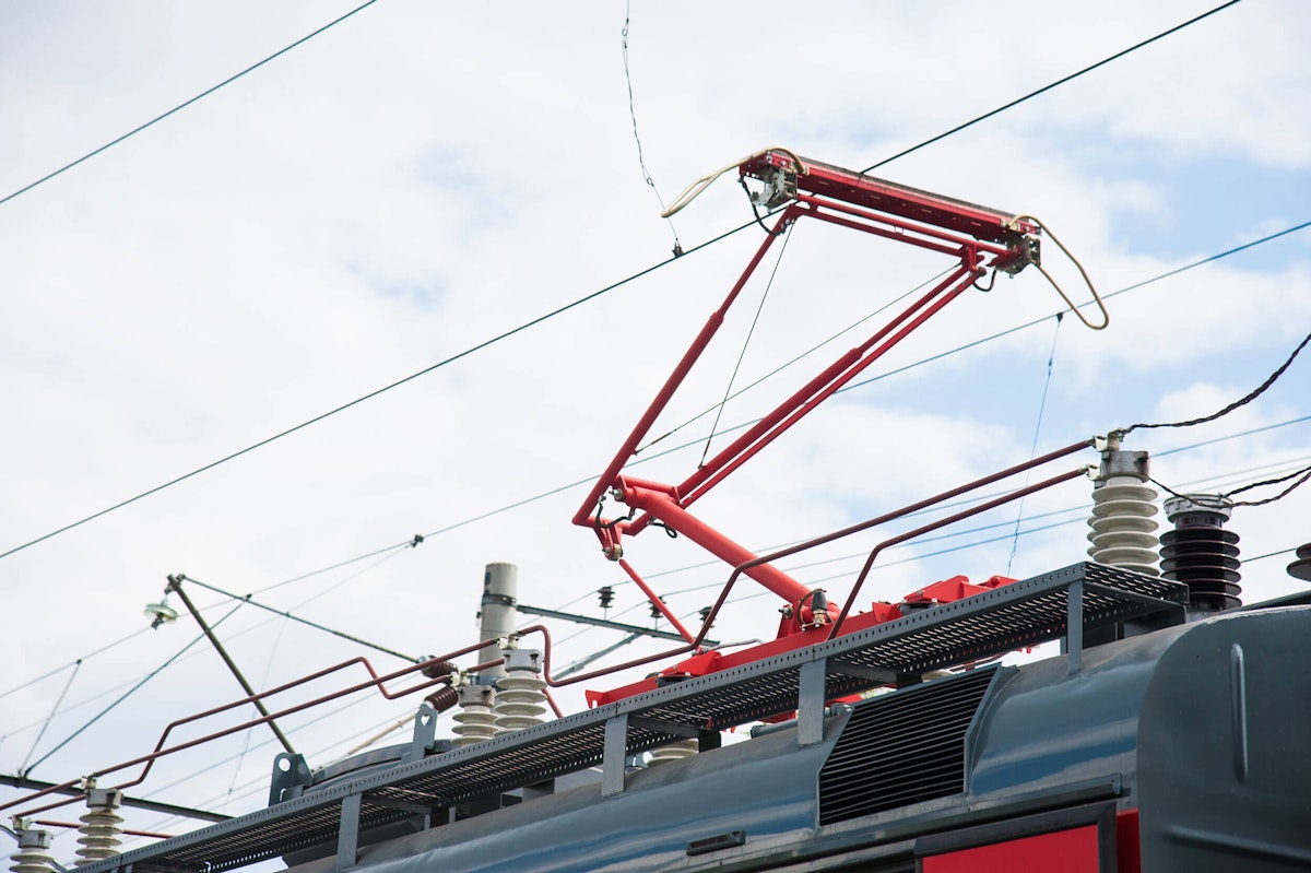
What is a pantograph?


Trains often use overhead systems to connect to electric power. These systems include a pantograph, an articulated, spring-loaded mechanism mounted on the train's roof that collects electrical power from overhead lines (OHL). The smooth and consistent interaction between the pantograph and OHL is critical with conventional trains. Still, it becomes even more pronounced with high-speed trains traveling at 350 km/h (~217 mph).


Typically constructed from lightweight but robust materials such as carbon fiber-reinforced polymers and aluminum alloys. They usually include a lower arm, an upper arm, and a contact strip, often made of carbon or a carbon-copper composite, to minimize arcing and wear. Real-time adjustments in contact force are controlled via pneumatic or electronically actuated systems to compensate for aerodynamic lift, wind pressure, and variations in wire height. Precision in pantograph design and control is critical to minimize contact loss and prevent damage to the pantograph and the catenary system.
What is the catenary system?
This article focuses on testing pantographs, but it’s essential to understand what the catenary system is and how it interacts.
An overhead catenary system (OCS) consists of tensioned wires that are somewhat flexible and a main overhead line (OHL) that supplies electricity to electric locomotives, trams, or light rail vehicles. It consists of one or more uninsulated conductors (or contact wires) suspended over the railway tracks and supported by structures such as poles, masts, or bridges. The contact wire is typically made of a hard-drawn copper alloy, which provides high conductivity and wear resistance. A system of weights or springs holds it at a constant tension to ensure good contact with the electric vehicle's pantograph.
In some catenary systems, a second wire, called a messenger or catenary wire, is suspended above and parallel to the contact wire. The contact wire is then suspended from the messenger wire by a series of vertical wires, known as droppers or hangers. This design allows for greater spacing between the support structures. It provides better current collection at higher speeds by reducing the sag of the contact wire and improving its vertical elasticity.
Catenary systems are essential for electric railways, providing a reliable and efficient means of power transmission to the trains. The design and maintenance of catenary systems are critical to ensure safe and uninterrupted railway operations. Factors such as voltage, current capacity, train speed, and environmental conditions are considered in the design of these systems.


Why is an optimal connection between a pantograph and the OHL crucial for railway operation?
A reliable connection of the pantograph and catenary system ensures continuous and stable electrical power to the train. Poor interaction can lead to arcing, power losses, or even complete disconnection, causing delays and operational failures. A good connection also prevents damage to infrastructure and equipment.
Excessive wear, mechanical stress, or irregular contact forces can damage both the pantograph’s carbon strips and the overhead wires. This leads to higher maintenance costs, frequent repairs, and potential service disruptions. A good connection also enhances safety and reliability by minimizing the risk of “dewirement,” when a pantograph detaches from the wire. This can lead to severe accidents or damage to infrastructure. Consistent performance also ensures reliable train operations at high speeds, reducing the likelihood of service interruptions.
Electrical issues
Arcing & Sparking
Intermittent contact causes electric arcs, damaging pantograph strips and OCS wires.
Generates electromagnetic interference (EMI), disrupting onboard electronics.
Voltage Drops & Power Interruptions
Inconsistent current collection leads to traction power loss, which reduces speed or can even cause trains to stall.
May trigger emergency braking, causing delays.
Mechanical wear & damage
Accelerated Wear of Pantograph Carbon Strips
Abrasion or chipping due to uneven contact forces
Increases maintenance frequency and costs.
Catenary Wire Damage
Grooving, nicks, or breaks in overhead wires require costly repairs.
Safety hazards
Fire Risk
Sustained arcing can ignite flammable materials near tracks (e.g., dry vegetation).
Pantograph Entanglement or Snapping
Severe cases may cause pantograph failure, which can lead to the collapse or derailment of the OCS.
Performance & efficiency loss
Speed Restrictions
Poor contact forces trains to slow down, disrupting schedules.
Energy Inefficiency
Power fluctuations increase energy consumption (e.g., regenerative braking failures).
Financial & operational impact
Higher Maintenance Costs
Frequent replacement of pantographs and catenary wires.
Service Disruptions
Disconnection causes delays and operational failures.
Unplanned downtime affects rail operators and freight logistics.
Regulatory Penalties
Non-compliance with safety standards (e.g., EN 50367, UIC 794).
These factors collectively impact efficiency, cost, and passenger safety, making optimal pantograph-catenary interaction vital for modern railway systems.
Testing pantographs and monitoring the catenary network
Testing the performance and reliability of railway pantographs operating at 15 kV and 25 kV AC requires rugged instrumentation with high-resolution analog-to-digital converters (ADCs). Various sensors are placed strategically to measure critical parameters related to the pantograph's interaction with the overhead line.
The primary goal is to ensure consistent contact force, minimize wear and tear on the pantograph and the OHL, and prevent disruptions to the train’s power supply. Standards related to this testing include EN 50317 and EN 50367.


Sensors used for pantograph testing and catenary network analysis
Accelerometers
Accelerometers are crucial for measuring the vibration and acceleration in all corners of the pantograph head. Engineers measure dynamic behavior under different operating conditions, such as speed and track geometry, then analyze vibration frequency and amplitude to identify excessive bouncing, dynamic instability, or structural resonances.
Accelerometer data helps assess the pantograph's ability to maintain stable contact with the OCS and identify areas prone to fatigue or damage.
Force sensors
Force sensors are installed on every corner of the pantograph to quantify the vertical contact force between the pantograph head and the catenary wire. Maintaining an optimal contact force is essential: insufficient force can lead to arcing and loss of contact, while excessive force can cause undue wear on both the pantograph and the catenary.
The force measurement chain provides real-time data on the contact force, enabling engineers to evaluate the pantograph's performance under dynamic conditions and verify the effectiveness of its active or passive force control systems.
Displacement sensors
Monitoring the pantograph's vertical displacement and height relative to the track and the OHL is vital for understanding its dynamic movement and ensuring it operates within safe limits. To get from acceleration to velocity and displacement, the acceleration function is integrated with respect to time.
Far more direct are Displacement Sensors, such as potentiometers or draw-wire encoders, because they can be used to measure the vertical position of the pantograph head. This data helps assess the pantograph's ability to follow the catenary wire's undulations and identify any excessive vertical movement that could lead to loss of contact or mechanical stress. In addition to overall contact forces and accelerations, understanding the distribution of force along the length of the contact strip is essential for optimizing wear and current collection.
Additionally, measuring the overall height of the pantograph provides critical information for safe operation, ensuring it remains within the permissible clearance limits under bridges and tunnels.
Infrared (IR) cameras
IR cameras can, for example, also measure the temperature of the pantograph head, particularly the contact strip and the contact area with the catenary wire. Elevated temperatures can indicate excessive friction due to high contact force, poor lubrication, or arcing caused by intermittent contact.
Monitoring the temperature in real-time allows engineers to detect potential overheating issues that could lead to premature wear, damage to the pantograph or catenary, and even power interruptions. The thermal images captured by the IR camera can provide valuable information about the health and performance of the pantograph's contact interface.
OPTRIS brand cameras are ideal for this application and are fully compatible with Dewesoft's DAQ systems. Unlike conventional temperature sensors, such as thermocouples, RTDs, and thermistors, IR cameras can measure without contacting the unit under test.
UV probe
UV probes are useful for arc detection. For example, the UV-Arc sensor measures the intensity and length of a UV arc event. Measuring the quality of the contact between a pantograph and the contact wire allows the location of wire defects. It complies with EN 50317. The UV-Arc sensor contains a very photodiode with an additional filter to suppress solar UV radiation.
The data collected from these sensors is typically fed into a Dewesoft DAQ system for real-time monitoring, recording, and analysis. This comprehensive instrumentation enables engineers to thoroughly evaluate the performance of 15 kV and 25 kV railway pantographs under a wide range of operating conditions, thereby contributing to improved reliability, reduced maintenance costs, and enhanced safety in railway operations. The analysis of this data can inform design improvements, optimize maintenance schedules, and provide valuable insights into the long-term behavior of pantographs and their interaction with the overhead catenary system.
Dewesoft networked DAQ topology
The DAQ system is centered around Dewesoft’s OBSIDIAN models, which are configured for both pantograph (top-oriented) and in-vehicle measurements (railway-oriented). Ruggedized OBSIDIAN models are utilized due to their resilience against shock, vibration, and extreme temperatures. They accept isolated, modular signal conditioning cards with appropriate analog-to-digital conversion required to analyze the overall behaviour. Additionally, they have the digital interfaces needed to connect cameras, GNSS position and speed interfaces, inertial measurement units (IMUs), and bus data from MVB, CAN, or even Ethernet.
At the heart of OBSIDIAN is an embedded ARM processor running a highly stable LINUX® operating system and DewesoftRT embedded DAQ software. The system is designed for maximum stability in long-term measurement applications and can upload data to the cloud or a traditional SFTP server.


A mobile network router connects the central DAQ unit and logger with the outside world, supporting 5G, 4G LTE, 3G, and WiFi 5 (802.11b/g/n/ac).
Data download and visualization
DewesoftX software is used to replay, validate, and analyze data files uploaded from the Dewesoft OBSIDIAN instrument. DewesoftX is provided at no charge with all Dewesoft instruments. There are no licenses or maintenance fees required throughout the system's lifetime. Certain advanced analysis features are paid options, but the basic package is included with the system. DewesoftX can be installed on multiple Windows computers, allowing every engineer to access the data.
Visualize data anywhere, anytime
Dewesoft Historian software enables the visualization of all data from a server and web-based platform from anywhere.


Summary of the benefits of the scalable solution from CETEST and Dewesoft
Measuring the interaction between a pantograph and overhead line and complete catenary at high voltage levels allows analysis of running behavior and catenary infrastructure, including:
Force measurement for contact position analysis and fatigue strength analysis
(ready to be used for pantograph control purposes as well)Displacement and movement measurement
(ready to be complemented with electric power measurement and analysis in the vehicle),Vibration measurement for oscillation and frequency analysis
(ready to be complemented by bogie frame or instrumented wheel measurement),IR camera-based temperature measurement at the contact point.
Furthermore, CETEST's commitment to precision and accuracy extends to the meticulous calibration and traceability of measurement data. In their ISO 17025 certified lab they calibrate the overall instrumented pantograph.
By combining expert methodology, state-of-the-art equipment, and adherence to international standards like the EN 50317, the European standard for railway applications that specifies the requirements for measuring and validating the dynamic interaction between a pantograph and an overhead contact line, CETEST plays a vital role in enhancing safe railway operation.
You can add Dewesoft Power Analyzer, providing accurate measurement of electric power for transformers and electric machinery.
Autonomous networked data logging for testing and long-term monitoring provides:
Automatic data file upload to cloud (SFTP) and infrastructure analysis
Continuous data stream to live web-based monitoring software
Geographical map-based data analysis, localizing critical sections
Conclusion
The partnership between CETEST and Dewesoft offers a scalable measurement solution for rail engineers, enabling comprehensive multi-physics signal acquisition. This capability provides precise insights into railway infrastructure, individual system elements (like bogies and traction motors), critical components (such as pantographs and wheels), and the overall vehicle behavior. By scaling this integrated solution, rail engineers can make data-driven decisions to improve safety, operational efficiency, and extend the lifespan of railway assets, ultimately contributing to a more reliable and efficient railway network.
Please contact CETEST or Dewesoft to move your next railway project forward.
