


How To Measure Torque?

February 12, 2022
In this article you will learn about signal processing with enough detail that you will:
Understand what torque is at the top level
Learn how torque is measured
See how torque measurement works in DAQ applications
What is torque?
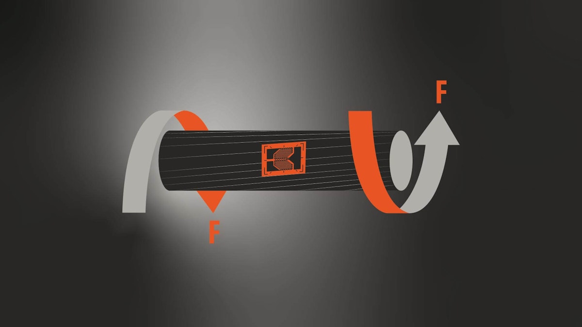
If you remember from physics class, force is an input that changes the motion of an object over time. For example, a simple linear force can push (or pull) mass in a state of rest, changing its velocity by accelerating it over time. Torque is a force that causes an object to spin around a rotational axis. Torque is therefore a “twisting force,” aka a rotational force.
The most obvious example of torque is the driveshaft in your car. The amount of torque that the motor is able to generate in that shaft determines the car’s ability to do work. Torque is a vector, meaning that it acts in a certain direction.
Torque is a “twisting force” that is intended to rotate or turn a driveshaft, screw, bolt, or wheel.


Torque can also be referred to as the moment or moment of force. Torque in general is given with the symbol \(\tau\) (the Greek lowercase letter “t”). The SI-derived unit for torque (moment of force) is \(N⋅m\) (Newton meters).
In the USA, torque is often expressed in foot pounds (\(ft/lbs\)). To convert \(N⋅m\) to \(ft/lbs\), simply divide the \(N⋅m\) value by 1.356.


Why do we need to measure torque?
Measuring the mechanical torque of rotating shafts is essential when designing, commissioning, and troubleshooting all kinds of machines. Knowing the true mechanical torque of a shaft, propeller or other rotating member is the only way to know that it is meeting its specifications.
In some applications it is critical to know what the torque is at all times, to guard against potentially dangerous excess torque that could lead to system damage or failure. Torque measurements are an important part of predictive maintenance.
What are the main types of torque?
There are two kinds of torque: rotary torque and reaction torque:
Rotary torque aka rotational or dynamic torque
Reaction torque aka stationary or static torque
Rotary (aka rotational or dynamic) torque
Objects like shafts, turbines, and wheels that rotate many times (or endlessly) around an axis, have rotary or “rotational” torque.
Reaction (aka stationary or static) torque
The static force applied to an object is called reaction or stationary torque. For example, when you put a lug wrench onto a bolt and then attempt to tighten it, you are applying reaction torque to it. Even if the bolt doesn’t turn much or at all, the reaction torque is still present. In this case, torque is being measured in less than one revolution.
How is torque measured?
Torque can be measured indirectly and directly. If you know the motor efficiency and the shaft speed, you can use a power meter to make an estimation of torque. This is an indirect way of measuring torque.
A better and more accurate way to measure torque is using a direct method, using reaction torque sensors or rotary torque sensors. What is the difference?
Reaction (static) torque sensors


A reaction torque sensor measures static or non-rotational torque.
A good example of a reaction torque sensor is a torque wrench. This tool is used to ensure that a correct amount of torque is applied to a bolt, nut, or another fastener. The base of the wrench has an adjustment to a desired amount of torque, and as the operator applies force, an audible click is emitted when the correct torque has been reached. These are often referred to as “click” torque wrenches, and they offer several adjustable set points.
Digital torque wrenches have a needle gauge or a digital display that shows the applied torque. Some electronic models, particularly those intended for factory work, have a memory that stores each operation for documentation and quality control purposes.
For a simple demonstration of how to use a “click” torque wrench, see this video:
Reaction torque sensors use either a quartz-based piezoelectric sensor or a strain gage sensor to measure the torque. There are many types and variations of torque wrenches and torque screwdrivers available.
Rotational (dynamic) torque sensors
A rotational torque sensor is a transducer that converts rotational torque to an output that we can measure, display, analyze, and store. Rotational torque transducers are used for motor torque testing stands, internal combustion engine tests, electrical motor tests, driveshafts, turbines, generators, and more.
There are both direct and indirect methods for measuring torque.
Indirect torque measurement methods can be cheaper and easier to implement on an existing shaft, but they are not as accurate as direct torque measurement. If you know a motor’s efficiency, and you can measure its shaft speed and current consumption, you can estimate torque this way.
Direct torque measurement methods are more accurate than indirect methods. Most of them involve the use of a strain gage mounted on the drive shaft. This sensor directly measures the twisting force on the shaft itself.


When the shaft is turned by the motor, it will twist very slightly. Due to the stiffness of steel, the twisting is impossible to see with the naked eye, but it can be detected by strain gages that are bonded to the shaft. An arrangement of four gauges comprises a Wheatstone bridge, whose output is balanced and conditioned by the rotary torque measuring system.
The output of this strain gage can be directly wired (if possible) or telemetered wirelessly to the torque measurement or DAQ (data acquisition)


Inside the rotary torque sensor itself, the outputs from the strain gage sensors mounted on the shaft are sent to the electronics using a slip ring (strain gage sensors must be powered). Alternatively, a brushless or inductive sensor connection can be used, allowing higher speeds and less physical wear and tear, resulting in less maintenance in the long run. Angle and RPM can be measured contactlessly as well.
DAQ systems from Dewesoft are ideal for measuring all physical parameters, including torque. They provide isolated signal conditioning that ensures low-noise and high-accuracy data acquisition. They also provide high-speed counter/RPM/encoder inputs that are ideal for simultaneously measuring shaft speed, angle, and position. In Dewesoft DAQ systems, analog and digital counter data are precisely synchronized, which is important for every application - but especially when conducting rotational and torsional vibration tests. More about that in the next section.


Permanently installed rotary torque measurement systems
In the system shown above, a rotary torque sensor is mounted between the motor and a brake, using couplings on each side. The shaft running through the sensor is equipped with a strain gage sensor that measures the twisting force on the shaft. The output of this signal is conditioned and sent to a DAQ (data acquisition) measuring system, or simply to a digital display or alarm system if monitoring but not recording the data is required.
Rotary torque sensors are optionally equipped with an encoder that outputs the shaft speed and angle very accurately. These outputs are used for torsional and rotational vibration studies. Speed measurement and angle outputs are essential in dynamometer applications, where they are used to calculate output power (expressed in \(HP\) or \(Kw\)) and motor efficiency.
Temporarily installed rotary torque measurement systems
For non-permanent rotary torque measurements, strain gauges can be mounted directly to the drive shaft. A small, battery-powered interface powers the sensors and wirelessly telemeters the data to a nearby processing unit, from which it can be recorded, displayed and analyzed using a DAQ system.


Wireless sensors from Parker-Lord are compatible with DewesoftX DAQ software, and can therefore be integrated into DAQ systems of any scale, from a single channel to hundreds of distributed channels.
Order analysis applications
Torsional vibration is a source of failure on rotating shafts. Rotational and torsional vibration analysis is an important tool for troubleshooting shafts, crankshafts, gears in automotive, industrial, and power generation applications.
What is torsional vibration?
Torsional vibrations are angular vibrations of an object, typically a shaft along its axis of rotation. They are mechanical vibrations caused by time-alternating torques which are superimposed on the otherwise steady running speed of a rotating shaft. In automotive engineering torsional vibration is primarily caused by fluctuations in engine power output.
Torsional vibrations are evaluated as the variation of rotational speed within a rotation cycle. RPM variations are typically induced by a rough driving torque or a varying load.
What is rotational vibration?
Rotational vibration is simply the dynamic component of rotational speed. If we measure the rotational speed of the shaft with high precision, we will notice that we get a high deviation of rotational speed in some regions of the run-up. This is caused by the angular vibration crossing the angular natural frequency of the shaft. It is calculated by cutting off the DC component of the rotational speed or the rotation angle
The level of torsional vibration is influenced by a number of parameters, such as material properties and operating conditions such as temperature, load, RPM, etc.
How to measure rotational and torsional vibration
This short video provides a basic introduction to how to make these important measurements, including the basic theory behind, it and the practical benefits.
The DewesoftX torsional vibration solution automatically calculates several different parameters:
Rotational angle: filtered angle value of vibration
Rotational velocity: filtered velocity vibration value
Torsional angle: the Dynamic torsional angle that is the angle difference from sensor 1 to sensor 2
Torsional velocity: difference in angular velocity from sensor 1 to sensor 2
X-axis reference angle: the reference angle, which is always from 0 to 360 and can be used as a reference in angle based X-Y diagrams
Frequency: in RPM units
Calculations can be done either online in real-time or offline on the saved RAW data.
More information:

Summary
Torque sensors are used in hundreds of applications across virtually every industry. Reactive torque sensors are found in torque wrenches and other tools in thousands of applications across every industry.
In automotive applications, rotary torque sensors are found in engine test stands, dynamometers, test benches, and endurance test stand. But that’s just the beginning of their usage. They are also used for testing industrial air conditioning units, large-scale livestock and poultry feeders, robotic sporting, assembly and medical equipment, electrical power testing, and more.
Torque is an important measurement in so many fields and applications. Luckily there are sensors and transducers to measure it, and DAQ systems to display, record, and analyze it.