


History of Analog-to-Digital Converters (ADCs)

September 27, 2022
In this article, you will learn about ADCs (analog to digital converters). We will cover the topic in enough depth that you will:
Understand what ADCs are for and what they do
Learn about the history and development of ADCs
See how important ADCs are and how they are used today
Introduction
Today we take ADC technology for granted. But it wasn’t always this way. Before there was a way to digitize the analog world around us and then reproduce it, life was very different. So how did we get here? The answer lies in the history of analog to digital converters.
Communication. This human imperative was the impetus behind the invention of the analog-to-digital converter (ADC). In fact, nearly all of the technological innovations that led to the ADC are the result of engineers and scientists trying to improve the telegraph and telephone systems from 1900 through the 1950s.
What is an analog-to-digital converter?
An analog-to-digital converter, or ADC, is a system that converts analog phenomena into digital signals that can be processed and stored on computers. In consumer terms, music is digitized today and available over the internet.
In the world of scientific measuring instruments, virtually all measurands (measured quantities) are digitized, i.e., converted to the digital domain. The analog outputs of sensors like thermocouples, strain gauges, accelerometers, force and displacement sensors, and more, are digitized for recording, display, and analysis purposes.
Learn more:


The 1910s: vacuum tubes
The first of these key enabling technologies was the vacuum tube, invented in 1906 by Lee DeForest. Vacuum tubes (aka “valves” in the UK) are amplifiers. They were essential for the telephone system, which was reliant on repeaters to boost signal levels over long distances.

")
The 1920s: pulse code modulation
At the same time, engineers at Western Electric were seeking to increase the amount of data that could be carried across telegraph lines. In 1921, Paul Rainey patented the concept of “pulse code modulation” (PCM).
He used photocells, galvanometers, and relays to encode information on one side of the circuit and decode it on the other. In this way, he could push more information across the telegraph lines without needing to increase the system’s overall bandwidth.
The 1920s: the Nyquist theorem
Also in the 1920s, Harry Nyquist was developing his famous theorem - The Nyquist Theorem, also working on increasing the telegraph system’s throughput despite its fixed bandwidth.


He determined that if a signal was sampled at regular intervals with at least twice the speed of the fastest movements within the signal, the signal could be reconstructed on the other end of the transmission without loss.

.")


The 1930s: PCM improvements
By 1937, Alec Harley Reeves, working in the Paris office of International Telephone and Telegraph (IT&T), had greatly improved upon Rainey’s PCM designs of the previous decade. He was able to digitize analog signals with 5-bit resolution, with a sample rate of 6 kHz/second. It was based on comparing a generated ramp voltage with the signal’s voltage and generating a pulse when they were equal.


This pulse then reset a Set/Reset flip-flop circuit, which in turn generated a pulse whose width was proportional to the signal level at that time. By using a counter, this stream of PCM outputs was “digitized,” i.e., converted to a series of numbers. By reversing the process and applying a filter at the end, these numbers could be converted back to analog again. This was a huge breakthrough in analog to digital conversion, and the inverse.
The 1940s: the first SAR ADCs
In a cooperation agreement with IT&T, Bell Labs continued Reeve’s work, inventing the successive approximation ADC - SAR ADC. But World War II was raging, and their work was dedicated primarily to finding ways to encrypt voice communication for military applications. Accordingly, most of these inventions did not see the light of day until after the war.
Up until this time, the vacuum tube was the only amplifier available. Being somewhat flimsy and temperamental at times, they were a constant source of maintenance. Simply put, they often burned out and needed to be replaced.
Tubes also consumed a lot of energy. If you’ve ever touched a tube that was just being used, you’ll remember that they get hot, like incandescent light bulbs. Insects sometimes got into instrument cabinets and were burned to death by tubes, sometimes causing shorts. Urban legend says that’s where we get the term “bug” in software products today.
The 1950s: solid state amplifiers and the integrated circuit
But that all changed in 1954 when Texas Instruments engineer Gordon Teal invented the first silicon transistor based on germanium.


Teal's team created the first commercial silicon transistor and tested it on 14 April 1954. On 10 May 1954 at the Institute of Radio Engineers (IRE) National Conference on Airborne Electronics, in Dayton, Ohio, Teal revealed this achievement to the world, when he announced: "Contrary to what my colleagues have told you about the bleak prospects for silicon transistors, I happen to have a few of them here in my pocket."
Silicon and solid-state technology led to a rapid series of inventions, including:
1956 - The Solid State Amplifier (L.R. Wrathall, Bell Telephone Laboratories)
1958 - The Integrated Circuit (The “IC”) (Jack Kilby, Texas Instruments)
1959 - Monolithic Integrated Circuit (Robert Noyce, Fairchild Semiconductor)
1959 - The Planar Process for IC Manufacturing (Jean Hoerni, Fairchild Semiconductor)


In 2000, Jack Kilby was awarded the Nobel Prize in Physics for the invention of the germanium-based integrated circuit (IC). Robert Noyce’s independently developed monolithic version was based on silicon, which ultimately proved more practical. It was also easier to mass-produce and did not require external wires. Noyce later co-founded Intel Corporation.


The 1950s: dawn of the computer age
By the 1950s, military and space applications were driving the development of ADC and DAC technologies. In addition to the code and voice encryption applications so important during WWII, early computers were being used to calculate launch trajectories, weapons targeting systems, RADAR systems, and more. Their ability to “crunch numbers” faster than any mathematician led to their increasing use in research and development.
Developments in ADC and DAC technologies were now being driven largely by the computer world. The two are inextricably connected, of course: in order to be processed by a computer, information must be converted from the analog domain to the digital domain, and for us to receive the results from a computer, it must be converted back again.
The 1960s: COTS ADCs hit the market
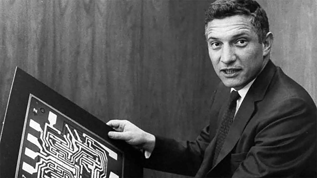
By the 1960s ADCs were no longer invented for a specific application, but they were offered as commercial, off-the-shelf (COTS) products by companies like Pastoriza Electronics, founded by MIT graduate James Pastoriza.
Pastoriza offered a 12-bit ADC 100 kHz ADC called the ADC-12U. It was based on a SAR chip and retailed for $800 USD (roughly $6,000 USD / €5,000 in today’s money). Analog Devices bought this company in 1969, using their products to enter the world of analog to digital converters in a very big way.
Other companies also offered commercially available ADC and DAC products, including Advanced Micro Devices, Analogic, National Semiconductor, Burr Brown, and Texas Instruments, just to name a few.
The 1970s: ADCs interface with CPUs
By the 1970s, virtually all of the basic ADC technologies that we use today were known. However, due to technological and manufacturing limitations, they were not all in production.
The 8-bit chips of the 1960s were supplanted by 10 and 12-bit versions. Manufacturers added “latches” to their ADCs and DACs, allowing them to interface easily with CPU (central processing unit) chips. Using one latch to command the ADC to take a sample and another latch to ask for the sample to be output, the ADC and CPU worked together seamlessly.

 ADC block diagram")
The main developments behind ADCs at this time were related to creating truly monolithic models, where all essential elements, like comparators, a clock, and voltage references, were placed on a single silicon chip. But even as manufacturing technology inched forward toward this goal, hybrid and modular ADCs ruled the market.
The 1980s: music goes digital
The 1980s saw the arrival of the first monolithic ADCs. They offered higher sampling rates and more vertical axis resolution than ever before. Demands from the medical and general instrument markets, the invention of the CD player for music, and the now digital worldwide telephone system pushed for these advancements, and they were answered.
16-bit and 18-bit ADCs were developed for music players, such as the compact disk (CD) player. Multi-channel ADC packages began appearing so that more than one signal could be digitized at the same time within a single chip.
This was quickly followed by the idea of adding a multiplexer onto the front of a single ADC, so that many signals (typically 8 or 16) could “timeshare” a single ADC chip. The outputs were not perfectly synchronized, of course, but if the application didn’t require it, it represented big cost savings.


Until now, most commercially available ADCs were successive approximation (SAR) and Flash types. They were fast, but limited in dynamic range because of their vertical axis resolution. The 1990s saw the arrival of the first commercially available delta-sigma type ADCs, which provided the high dynamic range required for noise and vibration applications.
The frequency-domain market (including voice band, shock, noise, and vibration) drove this requirement for greater dynamic range, for example, 20-bits. Today 24-bit delta-sigma ADCs are common. But they weren’t just good for frequency domain measurement. The signal output of a Type K thermocouple, while typically quite slow, requires a huge dynamic range to be fully represented. Delta-sigma ADCs are a perfect fit for this application.
From the 1990s to today, ADCs have continued to evolve. Sample rates are higher and higher to support emerging applications across multiple industries.
2010: DualCoreADC® technology invention
Data acquisition companies like Dewesoft have continued to push the technology of analog to digital converters. One of the most vexing problems in test and measurement applications is being able to predict the required gain for a particular channel. Engineers want to set the gain to get the highest possible amplitude axis resolution. But if the signal goes beyond their estimates, the signal gets clipped and the measurement is ruined. On the other hand, if you set the gain wide, the resolution, i.e., signal-to-noise ratio, is degraded.
In 2010, Dewesoft introduced the DualCoreADC® technology within their SIRIUS line of DAQ systems. This breakthrough solved the problem by using two separate 24-bit ADCs per channel, automatically switching between them in real time, and creating a single, seamless channel.
These two ADCs always measure the high and low gain of the input signal. This results in the full possible measuring range of the sensor and prevents the signal from being clipped. The video below explains how it works.
With DualCoreADC® technology Dewesoft achieved more than 130 dB signal-to-noise ratio and more than 160 dB in dynamic range. This is 20 times better than typical 24-bit systems with 20 times less noise.
2020: hybridADC technology
For years engineers have faced a difficult choice between delta-sigma ADCs (analog to digital converters) and SAR ADCs (Successive Approximation Register). Ten years after the invention of the DualCoreADC, Dewesoft solved this quandary with the invention of the HybridADC technology, which combines the best of both worlds.
While delta-sigma ADCs offer amazing dynamic range, 24-bit resolution, and built-in anti-aliasing capabilities, SAR ADCS offer higher bandwidth and perfect reproduction of impulse signals such as square waves.
Comparison of SAR and delta sigma ADC
| SAR ADCs | Delta Sigma ADCs |
|---|---|
| Highest sample rates | Not as high-speed as SAR |
| Usually limited to 16-bit resolution | Much higher 24-bit resolutionIdeal for sinusoidal/natural waveforms |
| Handle square waves without ringing/overshoot | Square waves cause ringing |
| No built-in AAF | Built-in AAF |
Applications that required a combination of both high-speed sampling and high resolution with anti-aliasing filters were forced to sacrifice one of these capabilities. Or buy two completely separate DAQ systems in order to handle these disparate requirements - not a very practical or efficient solution.
Dewesoft has solved this problem once and for all with HybridADC technology, developed for the SIRIUS XHS product line. The technology allows the user to select three modes of operation:
High Bandwidth Mode (Filter Off): 5 MHz bandwidth and 15 MS/s sampling rate, the SIRIUS XHS can perfectly acquire impulse, step, and square signals without any ringing or overshooting. This mode is perfect for transient recording and power analysis. This behavior is similar to typical SAR ADCs except with a higher sample rate and bandwidth.
Alias-free, High Dynamic Mode: Sampling up to 1.875 MHz and bandwidth up to 1 Ms/s, and 150 dB dynamic range. The data is totally alias-free, so all higher frequencies are fully rejected. This alias-free filter with a bandwidth close to the Nyquist criteria is used for frequency-domain analysis of signals such as sound and vibration. There is some ringing/overshoot on square waves and other impulse signals. This behavior is similar to classical Sigma-Delta ADCs except with a much higher sample rate and bandwidth.
Ring-free filtering: in addition, HybridADC converters offer ring-free filters with no overshoot on impulse signals, while still maintaining alias-free acquisition. The measurement remains alias-free because the cut-off frequency is set automatically to 20% of the sampling frequency.
Another very important thing to know is that each channel can be set individually to any of these modes, and to a different sample rate. Therefore, engineers don’t have to choose between one instrument or another, but they can use a single SIRIUS XHS instrument for all of their most important applications.
Even though engineers may select some channels to be high bandwidth and some to be alias-free, and even select different sample rates, filtering is designed in such a way that all signals are perfectly time aligned with zero phase shift.
Dewesoft HybridADC technology is a huge step forward in the world of data acquisition. It combines ring-free high-speed sampling with high dynamic range, and anti-aliased performance, covering all major DAQ applications with a single instrument. HybridADC technology blurs the line between high-speed SAR and high-bandwidth delta-sigma technologies by creating an ADC that provides the best of both worlds.
Summary
There is no doubt that ADC technology will continue to be driven by market demands. The world is only moving toward more and more digitization, and necessity is always the mother of invention.
So where are we today? What kinds of ADCs are on the market and what are they used for? This table provides a high-level overview, with those ADCs found in data acquisition (DAQ) applications shaded in green.
We hope that you have enjoyed this very brief history of analog to digital converters. A complete history would fill many large volumes and would start even earlier, as far back as the 17th century when Turkey developed a “digital” water metering system, but that’s another story.
Learn more: