


What Is TEDS Sensor Technology IEEE 1451.4?

July 18, 2020
In this article, we will discuss TEDS sensor technology as defined by IEEE-1451. At the end of this article you will:
See how TEDS can save you time and money and prevent setup-errors
Learn more about how TEDS works
Understand the benefits of using TEDS sensors with your data acquisition system
Are you ready to get started? Let’s go!
What is TEDS?
TEDS is an acronym that stands for transducer electronic datasheet. It is an EEPROM device embedded in the sensor or sensor's connector that contains information such as serial numbers, calibration dates, and other calibration factors. TEDS was introduced as IEEE P1451 and is a standardized way of storing key information about transducers, sensors, and actuators.
TEDS allows sensors to act in a truly “plug and play” fashion, eliminating some or all manual entry during setup and ensuring that the correct settings are applied. You may hear them referred to also as “smart sensors”.


Imagine a tiny non-volatile EEPROM installed inside the sensor itself which contains information like:
Sensor type
Serial number
Model name
Calibration data
Manufacturer name
This information can be read by the measuring system when the sensor is connected, simplifying the sensor setup—more about that in the next section.
TEDS was developed by the Institute of Electrical and Electronics Engineers (IEEE) as part of their “smart transducer” standard for sensors and actuators. The standard defines the digital communication protocol for reading and writing data to sensors. For in-depth information please refer to IEEE Std 1451.4 (2004)™, sometimes simply referred to as IEEE 1451.
Because it’s an open standard, TEDS devices should be cross-platform and interchangeable regardless of manufacturer. In-depth technical information is available from IEEE at P1451.4 - Standard for A Smart Transducer Interface for Sensors and Actuators--Mixed-Mode Communication Protocols and Transducer Electronic Data Sheet (TEDS) Formats.
Classes of TEDS devices
There are two classes of IEEE 1451.4 TEDS devices:
Class 1 devices use the same wires for both the analog signals and the TEDS digital communication. There is no interference because TEDS is not accessed during acquisition when the sensor output is temporarily reverse biased in order to read the digital data from the TEDS EEPROM.
Class 2 devices use separate wires for the analog signal and TEDS digital communication. This is common when a TEDS chip has been added to a sensor that did not originally have one.
The flexibility of TEDS is shown by its support of mixed-mode communication protocols like Class 1 and Class 2 above. Dewesoft DAQ systems can read both classes of TEDS sensors.
Check out Dewesoft's modern, digital data acquisition systems with complete TEDS compatibility


What is the purpose of TEDS?
Imagine that you are a test engineer and you are setting up a modal test. You have to connect 100 accelerometers to a measuring system. After the physical connections are made you must run the DAQ system’s software and set up each sensor individually, selecting the correct gain, entering the engineering units, applying the proper scaling and perhaps offset factors, naming each channel, and more.


This will take hours of painstaking referrals back and forth between the datasheet for each sensor and the DAQ system software, and sometimes tracing signal cables from the sensor to the DAQ system to make sure none were swapped. This kind of manual work and data entry is costly in time (and therefore money) and is also prone to error.
Now imagine a very different scenario. You connect each accelerometer. The data acquisition system’s software automatically communicates with the sensor and reads the TEDS information. It matches that sensor with an onboard sensor database and then sets the channel up completely automatically, applying the correct scaling and engineering units, signal conditioner gain, and other settings. The job that would have taken hours without TEDS technology is suddenly reduced to minutes.
Saving time, saving money, and eliminating human errors are the key purposes of TEDS. It also helps with ISO 9001 and QS 9000 calibration requirements.
Does TEDS harm sensor performance?
The TEDS chip has no adverse effect on a sensor’s performance. The chips themselves are tiny and add very little mass to the sensor, so in the case of accelerometers where sensor mass is a factor, or when the sensor is too small, the chip can be integrated into the connector, so there is no issue.
As mentioned above, in Class 1 TEDS devices the same signal line that the sensor uses to output its data also carries the TEDS information. But again this does not interfere with the signals because the TEDS chip is only read by the DAQ system’s signal conditioners when the sensor is not being used to measure data, e.g., during system setup, when a reverse bias voltage is used briefly during system set up to read (or write to) the chip.
What parameters can be stored in a TEDS chip?
The TEDS standard defines multiple sections of information that can be stored on the chip. In addition, it defines numerous templates that are used for various types of sensors, and for containing calibration information.
The four basic types of TEDS information:
Basic TEDS (64 bits)
Standard Templates (25 to 39, and 43)
Calibration Templates (40-42)
User TEDS
Let’s look at each one of these four types:
| Sensor Template ID | Bit Length | Allowable Range |
|---|---|---|
| Manufacturer ID | 14 | 17 to 16,381 |
| Model | 15 | 0 to 32,767 |
| Version Letter | 5 | A-Z |
| Version Number | 6 | 0 to 63 |
| Serial | 24 | 0 - 16,777,215 |
Following this basic TEDS information is an ID reference to the appropriate standard sensor template, numbered from 25 to 39 (plus 43):
| Sensor Template ID | Type of Sensor / Transducer |
|---|---|
| 25 | Acceleration & Force Sensors (IEPE) |
| 26 | Charge amp with an accelerometer |
| 27 | Microphone with integrated preamp (usually IEPE) |
| 28 | Microphone preamp (can also specify an attached microphone) |
| 29 | Microphones (capacitive) |
| 30 | High-level voltage output sensors (of all kinds) |
| 31 | Current loop (4-20 mA or 0-20 mA) sensors (of all kinds) |
| 32 | Resistance-based sensors (for potentiometric sensors use #39) |
| 33 | Bridge sensors (load, pressure, accel bridge linear output sensors) |
| 34 | AC Linear/Rotary Variable Differential Transformer (LVDT/RVDT) Sensors |
| 35 | Strain gauge sensors (linear or not, gage factor, etc.) |
| 36 | Thermocouples (all standard types are supported) |
| 37 | Resistance Temperature Detector sensors (RTDs) |
| 38 | Thermistors (using the Steinhart-Hart equation) |
| 39 | Potentiometric sensors (resistive voltage dividers) |
| 43 | Charge Amplifier (with an attached force transducer) |
You may be wondering what these sensor templates look like, so let’s look at one of the smaller ones:
| Property | Description | Access | Bits | Data Type and Range | Units |
|---|---|---|---|---|---|
| TEMPLATE | Template ID | 8 | Integer (value = 36) | - | |
| %ElecSigType | Electrical signal type | ID | - | Assign=0, “Voltage Sensor | - |
| %MinPhysVal | Minimum Temperature | CAL | 11 | ConRes (-273 to 1,770, step 1) | C° |
| %MaxPhysVal | Maximum Temperature | CAL | 11 | ConRes (-273 to 1,770, step 1) | C° |
| %MinElecVal | Minimum Electrical Output | CAL | 7 | ConRes (-25E-3 to 0.1 step 1E-3) | V |
| %MaxElecVal | Maximum Electrical Output | CAL | 7 | ConRes (-25E-3 to 0.1 step 1E-3) | V |
| %MapMeth | Mapping Method | ID | - | Assign=3, “Thermocouple | - |
| %TCType | Thermocouple Type | ID | 4 | B, E, J, K, N, R, S, T, or non-std | - |
| %CJSource | Cold Junction Compensation Required | ID | 1 | CJC required or compensated | - |
| %SensorImped | Thermocouple resistance | ID | 12 | ConRelRes (1 to 319k, ±0.155%) | Ohms |
| %RespTime | Response Time | ID | 6 | ConRelRes (1E-6 to 7.9, ±15%) | seconds |
| %CalDate | Calibration Date | CAL | 16 | DATE | - |
| %CalInitials | Calibration Initials | CAL | 15 | CHRS | - |
| %CalPeriod | Calibration Period | CAL | 12 | UNINT | days |
| %MeasID | Measurement Location ID | USR | 11 | UNINT | - |
Then we have an ID reference to one of three standard calibration templates, numbered from 40 to 42.
| Sensor Template ID | Calibration Template Name | Calibration Type |
|---|---|---|
| 40 | Calibration Table | Multiple data pairs define the output scaling of the sensor |
| 41 | Calibration Curve | A multi-segment, multi-polynomial calibration curve defines the output scaling of the sensor |
| 42 | Frequency Response Table | A set of amplitude-frequency data pairs defines the frequency response function of the sensor |
Then finally there is a user area, where additional information can be added by the user or the DAQ system. Dewesoft takes full advantage of these and also in its own TEDS-connected sensor database, as we will explain below.
Which sensors can be equipped with TEDS?
Every sensor can be equipped with TEDS. You might be thinking that there are some sensors so tiny that the EEPROM cannot be contained within them, which is true. In addition, there are sensors, like very small accelerometers, whose performance would be adversely affected by the additional mass of an EEPROM. There are also sensors designed to be used in extreme environments that the EEPROM could not withstand.
That’s all true, but the EEPROM can be installed alternatively in the connector (or sometimes the cable) that will plug into the DAQ system. Therefore, even the tiniest accelerometer can be adapted for TEDS, because the EEPROM is not inside the sensor, but is within the connector where it cannot affect the sensor and is separated from the harsh environment.
At the same time, there are cases where adding TEDS may not make sense. For example, you are using only one common thermocouple in your testing - is it worth the time and effort to add TEDS to it? Maybe not.
The beauty of TEDS technology is that you can apply it in a way that makes sense for you and your testing environment. Your system can be any combination of TEDS and non-TEDS sensors that you prefer.
Which sensors are most commonly equipped with TEDS?
Accelerometers
Microphones
Pressure sensors
Force sensors
Load cells
Torque sensors
MEMS sensors of many types
But it is important to note that any sensor can be equipped with TEDS. The above are simply the most commonly encountered.
How does TEDSwork within Dewesoft DAQ systems?
The TEDS interface is enabled by default within DewesoftX data acquisition software because TEDS chips are also installed within Dewesoft DSI (Dewesoft Smart Interface) adapters.


When a TEDS sensor is connected to your Dewesoft data acquisition system, you can open the channel setup screen and see the calibration information from the sensor as well as the scaling, serial number, etc.
This would already be a big help with any DAQ system because it eliminates having to refer to paper documents and possibly confusing one sensor with another. But this is just the beginning of the advantages of a Dewesoft system because Dewesoft X has a TEDS sensor database on board that automatically populates data from any and all TEDS sensors that you connect to the system!
Extending TEDS by storing DAQ signal conditioner settings
DewesoftX DAQ software matches existing sensors with their unique identifiers within the sensor database, which it keeps up to date. Furthermore, you can define exactly how you want the Dewesoft signal conditioner hardware to be set when each sensor is connected to it.
The Dewesoft implementation of TEDS goes beyond simply identifying the signal and applying the correct scaling - it actually allows the DAQ hardware to be configured according to your settings, every time that you connect the sensor, automatically.
There are two players on this team: the sensor and the signal conditioner. They must be matched not just in terms of function, but in terms of their settings. The gain settings of the signal conditioner have to match the output level of the sensor, right? And that’s just one parameter. So TEDS technology itself is only half the battle.
The major advantage of how Dewesoft DAQ systems implement TEDS is that in addition to the sensor data, all amplifier settings (range, type of input, filter, excitation voltage, et al) are stored.
Others have tried this by creating proprietary templates. But Dewesoft maintains the standard by taking advantage of the fact that multiple templates can be written to a single chip. Dewesoft writes the standard template first which keeps your sensors compatible with any other DAQ system. Then, one or more additional templates are written which allow all relevant signal conditioner settings to be written and retrieved by Dewesoft systems.
In the TEDS section of the DewesoftX setup screen we can see these multiple templates:


You can edit the sensor by clicking the lock symbol in the right upper corner of this section. Test managers can also set a password to disallow certain users to write TEDS information into the chip.
Changing engineering units
You might be wondering if TEDS locks you into the EU (engineering units) that the sensor manufacturer has defined. For example, for acceleration, you might prefer to work in [g] rather than [m/s2], or vice versa. American engineers may prefer Fahrenheit to Celsius for temperature readings, and so on.
This is actually no problem at all because while DewesoftX software is based on the standardized SI units for measurements, it also offers convenient drop-down menu conversion to other EUs. So even if your new TEDS accelerometer sets itself up in [m/s2], you can simply select “g” instead, and then write it to the template, so that g will be used from now on with this sensor. Multiple templates can be defined for each sensor, and each can be different according to your needs.
Dewesoft has embraced the TEDS standard fully but also added the ability to save the signal conditioner’s settings, allowing for the complete automation of channel setup.
TEDS case study


Mr. Roberto Basti is head of the Metrology Lab at The Marine Technology Research Institute in Rome, Italy. After his long experience with TEDS and Dewesoft DAQ systems like SIRIUS and DEWE-43, he commented:
"Our work changed when we learned about TEDS technology. We were used to providing calibration data to the field engineers to perform the measurement but now we can easily store these data directly in every sensor so that they can focus on the test without the need to worry about calibration parameters. We like this functionality so much that we installed the TEDS chip practically on every sensor we have."

Can I Add TEDS to My Non-TEDS Sensors?
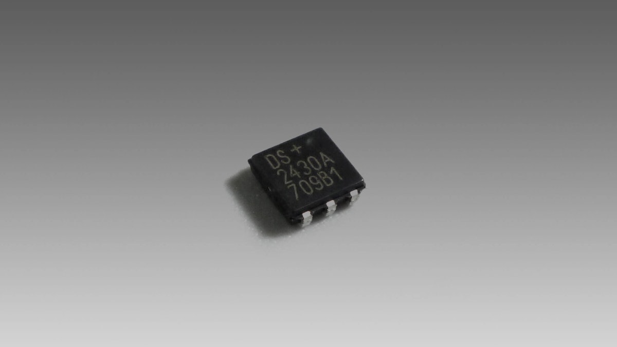
In a word, YES. Tiny TEDS chips are available on the market, such as the DS24B33 chip from Maxim, which has enough NVRAM to store amplifier settings in addition to all of the normal sensor and transducer information. These chips typically cost just a few US dollars or euros.
The Dewesoft STG signal conditioner has a dedicated TEDS input line which can be directly wired to the TEDS chip output.


It often works best to install the TEDS chip inside the sensor’s connector, rather than inside the sensor itself. Take a strain gauge, for example - a flat piece of foil substrate has no “inside.” But it usually has a relatively large DSUB connector that plugs into the DAQ system’s signal conditioner. This is the perfect place to install the tiny TO-92 case TEDS chip.
The TEDS chip can be programmed with the sensor information using either Dewesoft X data acquisition software or the free TEDS editor available from Dewesoft.


TEDS advantages
Faster set-up time and therefore reduced costs
Eliminates wiring errors
Improves data integrity by eliminating configuration errors due to selecting the wrong sensor or entering the wrong calibration values
The more channels a test has, the greater the advantage TEDS provides
Eliminating tedious manual entry improves both morale and ensures accuracy
Automation improves testing repeatability
TEDS is an open standard
TEDS sensors can be used in legacy DAQ systems that do not have any TEDS capability
Allows calibration record-keeping in compliance with ISO 9001 and QS 9000
Summary
TEDS is a powerful capability that is extremely useful when large numbers of sensors are deployed. It’s a tiny sensor that can be installed in any type of sensor, or within that sensor’s connector or cable. It eliminates tedious manual sensor and channel setup, saving time and money, and reducing human error in so doing.
It’s a proven standard that is cross-platform and supported by hundreds of sensors and DAQ system manufacturers. TEDS is a standard part of DewesoftX DAQ software, which is used across the entire Dewesoft product line.
Check out Dewesoft's modern, digital data acquisition systems with complete TEDS compatibility