


Direction Stability Test of a Braking Vehicle

October 26, 2020
In spite of the improvements in car chassis design over the past decades, steering drift during braking where the driver must apply a corrective steering torque in order to maintain course can still be experienced under certain conditions while driving.
A customer involved in military R&D needs to accurately measure the braking performance of vehicles, specifically how to accurately measure the brake centerline offset. Dewesoft provided a solution based on both the Dewesoft X Brake test plugin and Polygon plug-in in combination with GPS RTK technology.
Introduction
All vehicles show some degree of directional instability during straight-line braking since no real vehicles are truly symmetric.
By today’s standards of vehicle performance, handling, and drivability, even a minor deviation of this type is unacceptable. If not corrected by the driver, the vehicle may pull to a certain side of the road, a so-called brake pull. There are numerous sources of this behavior:
kinematical brake steer,
asymmetric mass distribution, or
brake imbalance.
There are three evaluation indicators of vehicle braking performance:
braking efficiency,
the constancy of braking efficiency, and
the directional stability of the braking vehicle.
The directional stability during braking is the performance that the car does not yaw, slip, or even lose its steering ability when braking.
In addition to recording the general brake test parameters like braking distance, initial braking speed, mean fully developed deceleration (MFDD), and other parameters, our customer needed to measure the yaw angle speed during braking, and the brake centerline deviation Shift amount, etc.
The yaw rate can be accurately measured by the gyroscope. How to accurately measure the brake centerline offset was a problem for the customer.


The customer
The causes of steering drift during braking need to be understood at the design stage. The customer in this project is in military R&D and needs a set of equipment that can accurately measure the braking performance of military vehicles.
In the European Standard ECE R13H Annex 3 Braking tests and performance of braking systems, 1.2.7 stipulates that the vehicle must not deviate from the 3.5m test road. Chinese standards GB7258-2017 also have explicit requirements for braking vehicles, stipulating that they cannot deviate from the 2.5m lane when braking.
ECE R13H Annex 3 paragraph 1.2.7. states:
The prescribed performance shall be obtained without locking of the wheels at speeds exceeding 15 km/h, without deviation of the vehicle from a 3.5 m wide lane, without exceeding a yaw angle of 15° and without abnormal vibrations.
It is therefore necessary to measure both the braking efficiency and the directional stability of the vehicle at the same time during braking.
The customer needs to calculate the following parameters:
braking distance,
initial braking speed,
mean fully developed deceleration (MFDD),
brake centerline offset, etc.
The brake centerline offset is defined as the vertical distance from the projection point of the test vehicle's center of mass on the ground to the vehicle's straight-line trajectory. How predict the straight-line trajectory of a vehicle under braking is the key to accurately measuring the offset of the brake centerline.
The measurement challenge
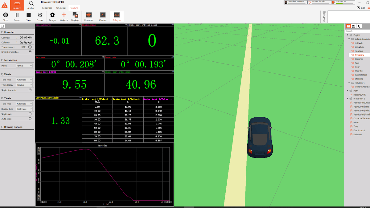
In DewesoftX data acquisition software, you can use the Brake testing module to perform a brake performance test, and the polygon plugin to measure the centerline offset of a braking vehicle.
However, the Polygon plugin can only measure the distance between the end position of the vehicle and the vehicle's heading extension line at the moment of braking.
Because the vehicle's heading angle will fluctuate slightly during straight driving before braking, measurements are inaccurate. For example, during a straight measurement, the heading angle can fluctuate up to 1.51°. Assuming a braking distance of 45m, the error of the measurement of the brake centerline offset is sin (1.51°/ 2) * 45 = 0.6m, which is obviously too imprecise.


The measurement solution
Combining the actual needs of customers, we proposed a test solution based on GPS RTK technology to the customer.
The system is composed of:
DS-IMU2 with RTK
RTK-RF-Modem
DS-WIFI3
DS-RTK-BASE


In terms of the calculation of test data, we proposed that our customers use the average of the heading angle one second before the test trigger as the predicted heading angle to calculate the straight-line driving trajectory. Hence, errors can be reduced caused by heading angle fluctuations or driving direction deviations.


Software settings
1) Using the statistical function in the mathematical formula to increase the average heading angle calculation channel.


2) Setting a virtual vehicle in the Polygon plug-in. The vehicle uses the average heading angle as its heading angle.


3) Adding prediction heading and using a trigger lock function.


4) Adding the channel for calculating the distance from the vehicle center to the predicted heading line.
This value is the brake centerline offset calculated using the average heading angle 1s before the trigger is the predicted heading angle.


Conclusion
This Dewesoft brake test solution can also be recommended to customers engaged in automotive braking research. Help them engage in automotive braking research and improve automotive braking stability.
This solution has been demonstrated to the customer, and the customers are satisfied and preparing for procurement.
Compared with competitors' solutions, the Dewesoft solution can well meet customer testing needs, with flexible parameter settings and high-accuracy data acquisition equipment for testing.