


Data Acquisition Synchronisation and Timing Methods

October 21, 2021
In this article, we discuss synchronization and timing methods in data acquisition and how they are used to synchronize Dewesoft Data Acquisition (DAQ) systems internally and with each other with enough detail so that you will:
See how analog and digital data are synchronized within a single system, and across multiple systems - whether directly connected or far apart.
Learn about timing methods and synchronize additional data streams from industrial devices, automotive and aerospace bus data, video (and more) with analog and digital data.
Understand why synchronization is necessary in the first place, and what benefits it provides.
Are you ready? Let’s get started.
Why do we need synchronization?
In the data acquisition (DAQ) world, data must be measured with the best possible accuracy and precision. When we think about those terms we normally think about measuring the amplitude axis. After all, it’s a measuring system, right? If we input 1.000 V, it should not measure 1.5 V or 0.8 V, for example. Those measurements would be inaccurate as well as imprecise.
But there is another axis when measuring time-history data: the time axis. It is equally important to know when something happened with respect to time and the other data, and for how long.
We almost take it for granted that if we input the same signal into several channels of a DAQ system, the resulting waveforms will be in perfect sync with each other in the recording. But this may not always be the case.
Take the example of an inexpensive multiplexed A/D card that uses a single ADC to digitize all channels. It can only digitize one channel at a time, so the channels that it captures are slightly skewed on the time axis. Because of the relatively low resolution of a computer screen, this skew might not be visible, but it’s there. When doing phase measurements, even a single sample shift can ruin the measurement.


Most medium and high-frequency measuring applications require that the data be synchronized within the DAQ system. When we input data into our DAQ system, and it is captured into a single data file, we expect all of the data to be synchronized together.
Accuracy on both the amplitude and time axes is fundamental to any time-history measuring instrument. If our measuring system can’t make good measurements, then what is the point of making measurements in the first place?
It is also sometimes required that multiple DAQ systems be synchronized together. This occurs when the test is too big for one DAQ system to handle, or when DAQ systems must measure at different locations, sometimes far away from each other. In order to analyze the data after the test, the data recorded by each DAQ system must be aligned with each other, and with reference to an external clock or time reference.
Synchronization timing sources
There are a number of timing sources and timing transport protocols that can be used for synchronizing DAQ systems, including:
IRIG Time Code
GPS PPS
NTP
EtherCAT
PTP V2
Let's see each one in detail.
IRIG (inter-range instrumentation group)
IRIG (Inter-Range Instrumentation Group) is a timing standard developed in the 1950s at the White Sands Missile Range in the USA, to allow the military to timestamp test data from a variety of instruments and sources, including DAQ systems, video cameras, flight test telemetry data, and more. Over the decades, the IRIG timecode standard has been adopted by many users around the world and is used for non-military users like power plants who need to synchronize power generation systems over a large geographical area.
GPS PPS
GPS PPS (Pulse Per Second) is an extremely accurate pulse transmitted by GPS/GNSS satellites. In fact, PPS timing accuracy on commercial GNSS receivers is approximately ±25 ns. The time itself is broadcast and references the precise pulse-per-second.
NTP (network time protocol)
NTP (Network Time Protocol) is a networking protocol for clock synchronization between computer systems. At +10 ms, NTP is less accurate than other methods mentioned here, but it is still quite useful in many applications.
EtherCAT
EtherCAT (“Ethernet for Control Automation Technology”) is a protocol that brings the power and flexibility of ethernet to the world of industrial automation, motion control, real-time control systems, and DAQ systems. EtherCAT’s built-in distributed clock provides excellent “jitter” performance far smaller than one microsecond (1 µs), which is equivalent to IEEE 1588 PTP (Precision Time Protocol), without the need for any additional hardware. EtherCAT systems can utilize the clock from the master, or be connected to an absolute external time reference, such as GPS or IRIG.
PTP (precision time protocol)
PTP V2 is an advanced master/slave protocol for distributing a clock among interconnected devices. It has been standardized under IEEE 1588-2008 and updated under IEEE 1588-2019. Note: PTP V2 is not backwardly compatible with the older PTP version IEEE 1588-2002. Like EtherCAT, PTP V2 is the transport mechanism and protocol, and it can be referenced to an external absolute time reference, like GPS or IRIG.
Synchronization types
There are essentially three types of synchronization that Dewesoft DAQ systems support. In addition, single or multiple DAQ instruments can be referenced to an external absolute time reference.
Synchronizing channels on a single DAQ system:
Internal Synchronization
Synchronizing channels between multiple DAQ systems:
Local Synchronization
Remote Synchronization
Absolute Time Reference
Internal channels synchronization

")
In the case of analog data, inter-channel synchronization is the job of our ADC system. The obvious approach is to use an ADC system with a separate ADC for each channel and to drive them with a single, extremely accurate clock pulse. The result is that all analog inputs are sampled at the same instant.


Adding digital channels and maintaining synchronization
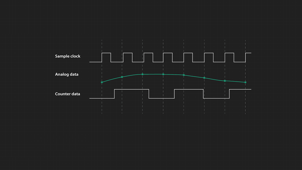
Separate ADCs per channel completely solves the problem of time skew with analog channels, but DAQ systems have other kinds of inputs, too. For example, most of them also provide digital inputs. Dewesoft DAQ systems have digital/counter inputs that can be used to capture discrete events such as a pulse train like this:


Digital inputs can also be used to measure speed, RPM, pulse-width, pulse output, and gear tooth sensors, and to interpret the quadrature outputs from rotary and linear incremental encoders.


The challenge is that these digital inputs must be sampled at much higher rates than our analog channels, so we cannot simply use the same sampling system for them. How can we then keep them in perfect sync with the analog data?
The solution is to use a much higher “master” sample rate for the entire system. In the case of Dewesoft instruments, this rate is more than 100 MHz. This allows the digital channels to be sampled at a very high rate. And when the user selects a sample rate for the analog channels, it is simply a divisor of the very high master rate, keeping all samples perfectly aligned within the system according to the master clock.
This seems like a logical approach, but how can the analog and digital data values coexist in the same system when they are coming in at different rates? What happens when digital data points fall in between analog data points?
The standard counters available on most DAQ systems today provide only integer resolution outputs (e.g. 1, 1, 2, 2). As a result, their outputs are always one sample behind the analog sensor data. This can be a real problem in applications like rotational or torsional vibration when a phase shift of even one sample can change the results.
Dewesoft’s patented SuperCounter® technology solves this problem completely by extracting floating-point values like 1.37, 1.87, 2.37, and then aligning them precisely in time with the rest of the data.
In fact, a SuperCounter is really two counters in one. The input is fed in parallel into both counters, and the sub-counter measures the exact time of the rising edge of the signal. Thus the real value of the counter with respect to the analog values is calculated, providing perfect alignment with not only the analog signals but all of the data coming into the Dewesoft system (CAN BUS, Video, etc.).
Please watch this short video, which includes a real-world comparison between the normal counting mode and the SuperCounting mode of Dewesoft systems.
Other data sources, like CAN bus data, are also synchronized with the analog data in all Dewesoft systems. Incoming digital values from the CAN bus are time-stamped precisely against the master clock. So even with a relatively simple DAQ system like the DEWE-43A, its analog channels, digital counter/encoder inputs, and CAN BUS data inputs are all in perfect sync with each other (~1 µs).
Synchronous and asynchronous data sources
There are many other data sources in addition to the built-in analog, digital, and CAN bus interfaces that Dewesoft DAQ systems can record. How are these handled with respect to synchronization? We will use video camera sensors in this discussion because there are both synchronous and asynchronous cameras available, allowing for easy comparison.
Adding video to data acquisition is one of the crowning achievements of the original Dewesoft 5.0 software going all the way back to 2001. Video adds a whole new layer of understanding to your data that sometimes cannot be achieved in any other way.
High-quality industrial cameras (such as Dewesoft’s DC-CAM series) have a sync port that allows their frame rates to be controlled by the Dewesoft system, keeping their pictures in perfect sync with the master clock. Such an interface is a SYNCHRONOUS DATA SOURCE because its data output can be controlled by the master clock via the standard SYNC port on Dewesoft DAQ systems.


But there are also inexpensive USB webcams that don’t have any sync port. They simply output video frames according to their own clock, based on the rate that you selected before the acquisition started. Since they cannot be externally synchronized, webcams output ASYNCHRONOUS DATA. How can this data be synchronized with the DAQ system?


In the absence of hardware synchronization, Dewesoft DAQ systems can use software synchronization to acquire data.
Using DewesoftX software, a DirectX webcam can be set to the desired frame rate and image size (according to the properties made available by the camera over the DirectX interface). So let’s say that we set the webcam to output 10 frames per second at 640 x 480 pixels each, and then we start the measurement.
When the first video frame arrives at the USB port of the host computer, DewesoftX time-stamps it with respect to the master clock. Each frame that arrives at the USB port will be time-stamped like this. When the data is reviewed, each video frame will be replayed at the same sample at which it was originally stamped.
This kind of “software sync” works, but it cannot be as precise as hardware sync because it takes time for the video frame to come through the USB to the CPU of the computer system and be seen by the software. The latency is in milliseconds, usually at least 10 ms and sometimes higher depending on the camera and the load on the computer.


To mitigate this latency, it is possible to input a DELAY value into the software in milliseconds. This offset will be subtracted from the time-stamp position.
Let’s say that you do a short test where you bang on a sensor while in the view of the webcam. When you replay the data you can use the cursors on the screen to measure how delayed the image is compared to the spike in the data. If it’s generally around 10 ms late, you can input that as your time delay value. When the data are replayed, the video frames will be played 10 ms earlier than the original timestamp.
Whether you are using a professional industrial camera with very precise hardware synchronization like the DS-CAM series, or an inexpensive webcam with software sync, it is possible to connect and record both SYNC and ASYNC interfaces in your Dewesoft DAQ system.
Learn more:

Dewesoft supported data sources and synchronization methods
Dewesoft DAQ systems are compatible with a very wide range of external data sources. It is beyond the scope of this article to describe them all in great detail, but here is a list with some basic facts, and links to learn more about each one of them:
| Data Source | Main Application | Models | Sync Type |
|---|---|---|---|
| Video cameras, Industrial | Multiple | DS-CAM series | |
| Webcams | Multiple | Generic webcams (DirectX compatible) | Software |
| InfraRed cameras | Multiple | Optris | Software |
| High-speed cameras | Multiple | Photron | Hardware |
| CAN Bus | Automotive | Dewesoft integrated | Hardware |
| CAN FD | Automotive | Dewesoft integrated | Hardware |
| XCP and CCP | Automotive | Via Dewesoft integrated CAN | Hardware |
| XCP and CCP | Automotive | Via Ethernet | Software |
| Flexray | Automotive | Vector brand cards | Software |
| LIN Bus | Automotive | Vector brand cards | Software |
| Kistler KiRoad | Automotive | Kistler KiRoad systems | Software |
| MTS Road Simulator | Automotive | EtherCAT connection to MTS | Hardware |
| GNSS / inertial platforms | Automotive | Oxford OxTS RT-series GNSS/INS and Genesys ADMA family gyro platforms | Hardware |
| Aerospace PCM Data | Aerospace | DS PCM FS2 | Hardware |
| iNET Next-Gen Telemetry Interface | Aerospace | Ethernet interface | Hardware (GPS or IRIG) |
| IRIG 106 Chapter 10 | Aerospace | Ethernet interface | Hardware (GPS or IRIG) |
| ARINC and MIL-STD-1553 | Aerospace | AltaDT hardware | Hardware (GPS or IRIG) |
| IRIG Time Code | Aerospace | Cross-platform | Hardware |
| GPS | Aerospace & Automotive | Cross-platform | Hardware |
| Ethernet | Multiple | Ethernet bus data | Software |
| EtherCAT® | Industrial | EtherCAT bus data | Hardware |
| Siemens S7 PLC | Industrial | Ethernet | Software |
| RS232 / RS485 | Industrial | Cross-platform | Software |
Single system synchronization summary
We learned in the first section above that Dewesoft systems have the capability of bringing in a wide variety of sensor data, digital data, video data, and data from many different interfaces. Those sources which have a clock that can be controlled by the DAQ system will be synchronized to the master clock very precisely: generally ~1 µs. Those sources that cannot be controlled will be time-stamped upon arrival at the DAQ system, generally with a time accuracy of ~ 10 ms.
So within a single Dewesoft DAQ system, you can record analog data from virtually every analog sensor in the world (voltage, current, strain, acceleration, sound, pressure, etc.), plus digital counters and encoders of all kinds, discrete digital pulses, CAN BUS, ARINC 429, MIL-STD-1553, RS232 data, video, infrared video, and so much more - synchronously. You can then replay it all on the screen, synchronously.
Multi-system synchronization
What if the analog and digital channels from a single DAQ system are not enough to do the test? What if we need to use two DAQ systems? Or ten DAQ systems? What if the DAQ systems cannot be physically connected to each other due to distance or physical barriers?
How can multiple DAQ systems be synchronized so that their data are precisely aligned on the time axis with each other? There are several ways this can be done, according to the physical locations of the systems. Let’s take a look at each major way to synchronize multiple Dewesoft DAQ systems together:
Local Synchronisation: this method is used when DAQ systems are placed close to each other and can be synchronized with cables.
Remote Synchronisation: this method is used when DAQ systems are placed remotely, even hundreds of kilometres away.
Local synchronization
“Local” means that the instruments are in the same room, and can be connected together easily with typical-length USB and SYNC cables. Virtually all Dewesoft instruments have a SYNC port precisely for this purpose.
Let’s say that we have a SIRIUS modular DAQ instrument. SIRIUS connects to a Windows computer via USB. The computer runs DewesoftX software, providing the user interface for the system, and its internal drive is where the data is stored.
In this small system, the SIRIUS module is the clock master by default. It is also possible for the computer to provide the master clock - more about this in the Absolute Time Reference section below.


Now let’s say that you purchase a second modular SIRIUS unit. You could connect that SIRIUS to a second computer and use it completely separately from your first system … or you could connect it to the first computer and convert that system from 8 to 16 channels.
Each SIRIUS has a USB interface that must be connected to the host computer. All of the data from both SIRIUS modules will be displayed on a single computer’s screen and stored in a single data file. All that is needed is to connect the two SIRIUS slices together using a simple SYNC cable. Microsecond-level accuracy is provided.


Using this method you could connect up to eight SIRIUS slices to a single computer and all of the data would be completely synchronized and stored in a single data file. But because very few computers offer so many USB interfaces, Dewesoft offers USB hubs that aggregate all of the SIRIUS modules into a single high-speed USB interface - so your computer only needs one USB interface. The sync cables are daisy-chained from SIRIUS to SIRIUS, and microsecond-level accuracy is still provided.


It should be noted that it is possible to synchronize the data from one Dewesoft DAQ system to another one without using the SYNC cable. This method has a time accuracy of ~ 10 ms, which is good enough for simple temperature or other low-speed measurements. This “soft sync” method requires no additional hardware. But in nearly all cases, the SYNC cable method is strongly recommended to ensure the best and most accurate synchronization possible.
Using SYNC cable among instruments
In the figure below, SYNC cables are daisy-chained from one instrument to the next. In the software running on the host computer (not shown), the DEWE 43A instrument on the left has been set as the “Clock/Trigger Master,” so the other DAQ instruments will be a slave to it. Their data will be streamed to the host computer as if they were coming from a single instrument. The trigger will also be shared from the master to the slaves to start and stop the acquisition.


Alternatively, you can configure the “master” DAQ instrument to output IRIG-B DC from its SYNC port, and the other instruments will be set to slave to that IRIG input. The accuracy in either configuration is ~1 µs.


Combining stand-alone and modular instruments
It should be noted that SIRIUS-based instruments like the R1, R2, R4, and R8 series from Dewesoft, include both SIRIUS modules AND a host computer. These instruments also have a sync port, so that SIRIUS modular DAQ instruments can be used to expand them exactly as shown above with a generic Windows computer.

 with SIRIUS modular expansion slice (left)")
Combining EtherCAT DAQ modules
Dewesoft’s EtherCAT-based instruments can be interconnected easily. This is one of the hallmarks of EtherCAT, in fact. The KRYPTON series are connected to each other via EtherCAT, which carries not only the digitized data but power and sync. The EtherCAT master controls the network of modules.


KRYPTON modules can be up to 100 m (328 feet) apart, so you can distribute them across a very wide area.
Combining high-speed USB DAQ and EtherCAT modules
Dewesoft EtherCAT-based DAQ systems have built-in internal synchronization - this is one of the hallmarks of the EtherCAT interface itself. A single cable interconnects instruments like KRYPTON modules, for example, carrying data, power, and clock information.
The EtherCAT master automatically disciplines the clocks of all connected slave devices and assigns their unique identification on the network. These are just some of the reasons why EtherCAT has become such a strong standard in the world of industrial automation and control.
You can mix high-speed Dewesoft and Dewesoft EtherCAT instruments together in almost limitless ways. Dewesoft computer hosts like the SBOX and the R series already have a built-in sync port for synchronizing additional DAQ modules. The KRYPTON CPU has an EtherCAT interface. If you’re using a regular computer there is a small SYNC JUNCTION device that will provide this capability.


As mentioned, EtherCAT devices can be located 100 m (328 feet) apart from each other, so this system can be distributed around a large area. KRYPTON modules can be daisy-chained, allowing a large-scale system to be created:


Even more, possibilities exist for Dewesoft instrument configurations:
 and KRYPTON (EtherCAT) DAQ modules")
Mixing the worlds of high-speed USB data and medium-speed EtherCAT data while still maintaining perfect internal time synchronization is built into the Dewesoft architecture. Looking at the illustration above, you can see that the SBOX CPU host is receiving all of the USB data from the two SIRIUS slices mounted above it, as well as the five EtherCAT KRYPTON modules.
The SIRIUS slices do NOT have to be fastened to the SBOX - they can be located within a USB cable distance away. The EtherCAT modules can be separated by up to 100 meters (328 feet) from each other. The SBOX provides the timing and synchronization of all data.
Please note that if we connect an external clock master to the SBOX such as GPS PPS, NTP, IRIG, etc, all of the data will be referenced to absolute time.
Learn more about EtherCAT:

Combining SIRIUS XHS systems via PTPv2
Available exclusively for Dewesoft SIRIUS XHS systems, PTP v2 is the latest version of the Precision Time Protocol (PTP) protocol, in which a clock master is used to synchronize all of the clocks on a computer network. PTP v2 provides ~1 µs clock accuracy across a LAN. PTP v2 is a big step forward from the original v1 released in 2002. PTP v2 has the kind of time accuracy and stability that data acquisition applications require.

The entire PTP v2 network can be referenced to any external time source (like IRIG, GPS PPS, etc as you will see in the Absolute Time Reference section) so that all of the devices on the network are referenced to that clock. PTP v2 has been eagerly adopted by financial transactions, cell phone tower transmissions, power distribution, and other networks that require time accuracy better than NTP, but which may not have easy access to GPS PPS.
Learn more about:
")
Remote synchronization
The above examples are great, but what if the distance between the DAQ instruments is too great, and there is no way to connect a sync cable? Imagine multiple DAQ systems spread across multiple floors of a spacecraft launch platform, all streaming data back 5 km (3 miles) to a control center. Or, multiple DAQ systems scattered around a large manufacturing plant.


In this case, we can use the Dewesoft NET software option to allow the systems to be connected together over ethernet using TCP/IP. This is standard ethernet, and it can be wired or wireless. There can be a direct connection via an ethernet cable from the DAQ system to the client computer, or they can both be connected to the same router or on the same network.
Using Dewesoft NET, one or more DAQ systems can be connected back to one or more data “clients.” Clients are simply Windows computers that can control the DAQ systems, view their data in real-time, and/or download entire data files when storing has been stopped.
Clients can also be configured to only VIEW the data, but not control the DAQ systems. A combination of control and view clients can also be used. Even when data is being streamed across the network to the client(s), it is also stored locally on the DAQ system(s) to protect the data against loss in the event that the TCP/IP connection is interrupted. Data can be transferred easily to the clients after the test if required.
There are three basic configurations to choose from:
1:1 Mode - Single DAQ system and single client
x:1 Mode - Multiple DAQ systems and single client
1:x Mode - Single DAQ system and multiple clients
1:1 mode - single DAQ system and a single client
1:1 mode works with a single Dewesoft DAQ system and a single client computer. The DAQ system and client are connected via TCP/IP protocol over any distance.
There are two types of operation: full remote control and data view only.
In FULL REMOTE CONTROL mode, the client computer is the master controller of the measurement system. It directly accesses the DAQ system’s setup screen and can start and stop measurement, configure triggering, and more. It’s just as if you were sitting in front of the DAQ system operating it, except that you are on a different computer … and this computer can be sitting right next to the DAQ system OR it can be kilometers/miles away.
In the VIEW ONLY mode, the measurement system acquires data, while the client computer can connect to it and view the live data. But this VIEW CLIENT cannot control the DAQ system. This is ideal when you want a user to be able to view the data, but not to control the measurement in any way. A VIEW client can “look, but not touch.”
x:1 mode - multiple DAQ systems and a single client


When the application requires more than one DAQ system to be used, it is possible to connect multiple systems together. They must be synchronized together to ensure that the data from these systems is aligned on the time axis.
To achieve this, we need either an internal clocking or an external clock. With internal clocking, one system is the clock master and the others receive that clock and lock to it. A simple SYNC cable is used to connect these clocks.
Or, we can use an external clock source such as IRIG or GPS. Additionally, all DAQ systems must run at the same dynamic acquisition rate. There are more details about absolute time synchronization in the next part of this document.
The client computer is always the master: it starts and stops the measurement of all DAQ systems in the network. This client can VIEW the data of any single DAQ system during measurement.
1:x mode - single DAQ system and multiple clients

The third network configuration is to have a single DAQ system controlled by one MASTER CLIENT and additional VIEW CLIENTS. The MASTER is able to change the measurement system setup, storing setup, start and stop storing, and much more. The VIEW clients can view a few channels from the DAQ system (up to the bandwidth limitation). They can view and store these channels on their local hard drives if they desire. The VIEW clients are passive observers: they cannot control or interfere with the test.
Learn more:
So, we can have a network of computer-based DAQ systems that are synchronized with each other, or to an absolute time source like IRIG or GPS PPS.
Absolute time reference
We have learned that the high-speed master clock within a given Dewesoft DAQ system allows all manner of inputs: analog, digital, etc to be acquired and synchronized with either hardware or software precision.
We have also learned that multiple Dewesoft DAQ systems can be connected locally and/or remotely, and be synchronized together using the clock of whichever device has been set as the “master” within the system. But what if we need the master clock to be synchronized to an absolute time reference?
First, we need an external clock source. Four external timing sources are supported by Dewesoft DAQ systems:
IRIG timecode
GPS PPS pulse
EtherCAT PPS pulse
NTP SYNC synchronization
PTP_V2 time synchronization (SIRIUS XHS only)
IRIG timecode
Dewesoft systems are compatible with several IRIG time codes. IRIG-B DC can be input to the SYNC connector. Other IRIG codes can be input using an external IRIG interface, such as the DS-GPS-CLOCK.


When IRIG is selected as the time source for the system, absolute time accuracy of ~ 1 µs is achieved. IRIG is a BCD format word that contains not just time but the day, month, year, etc. This is a great way to synchronize the system because of its accuracy and precision.
GPS PPS (pulse per second)
Dewesoft DAQ systems can use GPS PPS as an absolute time reference, without any distance limitation.
High-quality GPS receivers and IMU devices with GPS like those offered by Dewesoft, all provide a PPS output for time synchronization:
| DS-GPS-CLOCK | DS-VGPS-HS/HSC | DS-IMU1 | DS-IMU2 | |
|---|---|---|---|---|
| PPS output | Yes | Yes | Yes | Yes |
| IRIG B output | Yes | No | No | No |
| Interface(s) to DAQ system | USB | RS232 / USB, CAN, Analog, Digital | USB, RS232 | USB, RS232 |
| Navigation Systems Supported | GPS L1, GLONASS L1 | GPS L1, L2 GLONASS L1, L2 | GPS L1, GLONASS L1, GALILEO E1, BeiDou L1 | GPS L1, L2, L5 GLONASS L1, L2, GALILEO E1, E5, BeiDou B1, B2 |
| Main Applications | Time sync, basic positioning | Time sync, positioning, brake tests, ADAS | Time sync, Inertial Measuring Unit (roll, pitch, yaw) | Time sync, Inertial Measuring Unit (roll, pitch, yaw) |
Third-party GNSS receivers that have a PPS output are also able to serve as clock masters within Dewesoft DAQ systems, including Topcon GNSS, Novatel GNSS, Racelogic V-BOX, Microsat, and Dewetron V-GPS. Always check with Dewesoft technical support to ensure compatibility.
EtherCAT PPS
Dewesoft EtherCAT devices can be synchronized with ECAT GPS Junction which supports both PPS from GPS and compatible navigation devices as well as IRIG timecode. This interface allows all Dewesoft EtherCAT devices like KRYPTON and IOLITE to be synchronized to an absolute time reference.

NTP synchronization
In the setup section of DewesoftX software, you select an external time source and then choose NTP as your clock provider. Then in the additional dialog box, you enter the address of one or more NTP time servers. These would be connected to the DAQ system via ethernet. NTP is not as precise as the IRIG or GPS PPS methods, but it is sufficient for many applications.


| Type | Acc. | Best For | Compatible with |
|---|---|---|---|
| IRIG Timecode | ~ 1 µs | Stationary applications | All Dewesoft DAQ systems |
| GPS PPS | ~ 1 µs | Mobile or stationary applications | All Dewesoft DAQ systems |
| EtherCAT PPS | ~ 1 µs | Mobile or stationary applications | All Dewesoft EtherCAT systems |
| NTP | + 10 ms | Stationary applications | All Dewesoft DAQ systems |
| PTP_V2 | ~ 1 µs | Mobile or stationary applications | Dewesoft SIRIUS XHS systems |
PTP_V2 synchronization
SIRIUS XHS systems can be synchronized using all of the methods mentioned above PLUS PTP_V2 (but not the older PTP). This advanced timing protocol, standardized under IEEE 1588-2008 and updated under IEEE 1588-2019, is not backwardly compatible with the older PTP version (IEEE 1588-2002). IEEE-1588 is a master/slave protocol for distributing a clock among interconnected devices.
The entire PTP v2 network can be referenced to any external time source (like IRIG, GPS PPS, NTP, etc.) so that all of the devices on the network are referenced to that clock. PTP v2 has been eagerly adopted by financial transaction service providers, cell phone tower operators, power distribution systems, and other networks that require time accuracy better than NTP, but which may not have easy access to GPS PPS.
When you have multiple SIRIUS XHS devices you can use an external clock provider as PTP or a Dewesoft DAQ device (clock slave) as a PTP clock source.
Summary
In this article, you learned how all of the data sources connected to a single Dewesoft DAQ system are synchronized together. Some use hardware sync and others use software to sync.
Then you learned how multiple Dewesoft DAQ systems could be connected together to create a distributed DAQ system, and yet still maintain synchronization among and between all of the channels from multiple systems.
We showed how the Dewesoft NET distributed architecture can be used to spread these data acquisition systems out over a very wide area - even kilometres/miles apart from each other.
And finally, we showed how we could use one of several possible interfaces to provide single or multiple systems with a reference to an absolute time source.
They say that “timing is everything,” and this is never truer than with data acquisition.