


Dewesoft Data Acquisition Technology Explained

February 8, 2022
In this article we will learn about the most important data acquisition technologies that Dewesoft has invented and developed, describing them with enough detail that you will:
See what the major Dewesoft DAQ technologies are
Learn their principle of operation and how they came to be
Understand how they improve the DAQ process and its measurements
DualCoreADC® technology
A big challenge that has plagued engineers for years is setting the optimum gain for input channels. What if we have a signal that is usually less than 5 volts, but at times, the voltage can range upward dramatically to 100V?
If we set the resolution of the ADC (analog-to-digital converter) to accommodate the 0-5V data, the system will be overloaded when the signal rises past that. But if we set the gain to 100V, then the amplitude axis resolution will be poor when the signal is within 5V.
One solution would be to use two channels set to different gains and refer to one of them for the 0-5V data, and to the other one for the higher amplitude data. But this is very inefficient. We can’t possibly use two channels for every input signal as would need twice as many DAQ systems to do the same work. In addition, it would make data analysis after each test much more complex and time-consuming.
There was no good solution to this gain problem until Dewesoft invented the DualCoreADC®.


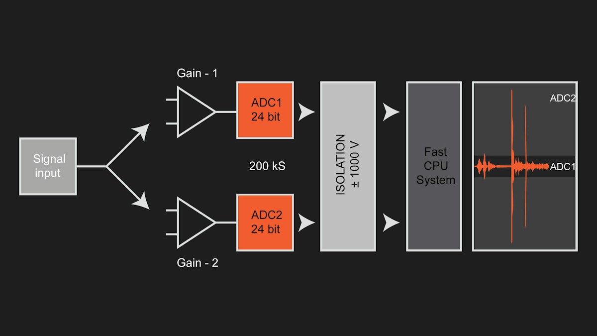
Dewesoft’s DualCoreADC® technology solved this problem by using two separate 24-bit ADCs per channel. It can automatically switch between them in real time and create a single, seamless channel. These two ADCs always measure the high and low gain of the input signal. This results in the full possible measuring range of the sensor and prevents the signal from being clipped.
And it’s not just for dynamic signals. Even with very slow signals like from most thermocouples, having the greatest possible amplitude axis resolution can be critical.
Imagine a thermocouple capable of measuring across a 1500° span. The more amplitude axis you have at the ADC, the more resolution the temperature signal will have. Keep in mind that each bit effectively doubles the vertical axis resolution. Dewesoft’s DualCoreADC technology is an important step forward in the science of making measurements with the highest possible dynamic range, no matter how large or small the signal may be at a given point in time.
With DualCoreADC® technology SIRIUS data acquisition systems achieve more than 130 dB signal-to-noise ratio and more than 160 dB in dynamic range. This is 20 times better than typical 24-bit systems with 20 times less noise. Dewesoft’s DualCoreADC-based SIRIUS DAQ systems offer sample rates up to 200 kS/s per channel.
But what if you require a system that provides channels with high dynamic range and anti-aliasing capabilities, but much higher sample rates on other channels? Then HybridADC technology will be great for you.
HybridADC technology
For years engineers have faced a difficult choice between delta-sigma and SAR ADCs (successive approximation).
While delta-sigma ADCs offer an amazing dynamic range, 24-bit resolution, and built-in anti-aliasing capabilities, SAR ADCs offer higher bandwidth and perfect reproduction of impulse signals such as square waves.
| SAR ADCs | Delta Sigma ADCs |
|---|---|
| Highest sample rates | Not as high-speed as SAR |
| Usually limited to 16-bit resolution | Much higher 24-bit resolution |
| Handle square waves without ringing/overshoot | Ideal for sinusoidal/natural waveforms |
| No built-in AAF | Square waves cause ringing |
| Built-in AAF |
Applications that required a combination of both high-speed sampling and high resolution with anti-aliasing filters were forced to sacrifice one of these capabilities. Or buy two completely separate DAQ systems to handle these disparate requirements.
Dewesoft has solved this problem once and for all with HybridADC technology, developed specifically for the SIRIUS XHS product line. The technology allows the user to select between two modes of operation:
High bandwidth mode (Filter Off): 5 MHz bandwidth and 15 Ms/s sampling rate, the SIRIUS XHS can perfectly acquire impulse, step, and square signals without any ringing or overshooting. This mode is perfect for transient recording and power analysis. This behavior is similar to typical SAR ADCs except for a higher sample rate and bandwidth.
Alias-free, high dynamic mode: Sampling up to 1.875 MHz and bandwidth up to 1 Ms/s, and 150 dB dynamic range. The data is alias-free, so all higher frequencies are fully rejected. This alias-free filter with a bandwidth close to the Nyquist criteria is used for frequency-domain analysis of signals such as sound and vibration. There is some ringing/overshoot on square waves and other impulse signals. This behavior is similar to classical Sigma-Delta ADCs except with a much higher sample rate and bandwidth.
Another very important thing to know is that each channel can be set individually to any of these modes, and to a different sample rate. Therefore, engineers don’t have to choose between one instrument or another, but they can use a single Dewesoft instrument for all of their most important applications.
Even though engineers may select some channels to be high bandwidth and some to be alias-free, and even select different sample rates, filtering is designed in such a way that all signals are perfectly time aligned with zero phase shift.
Dewesoft Hybrid ADC technology is a huge step forward in the world of data acquisition. It combines ring-free high-speed sampling with high dynamic range, and anti-aliased performance, covering all major DAQ applications with a single instrument.
Learn more:


SIRIUS® XHS technology
The SIRIUS® XHS high-speed data acquisition systems incorporate Dewesoft’s HybridADC signal conditioning technology (described above), with additional advanced capabilities. The instrument looks the same as the famous SIRIUS DAQs available since 2010, but the system consists of a completely redesigned heart and brain.


SIRIUS XHS devices provide the ultimate in DAQ performance and versatility, including:
The revolutionary Hybrid ADC technology offers analog signals converted to digital at 15 MS/s per channel with 5 MHz bandwidth. It also has the ability to perform both ring-free high-bandwidth, 16-bit sampling, and 24-bit alias-free sigma-delta type sampling up to 1 MHz bandwidth per channel.
Redesigned amplifiers that support the higher bandwidths of the Hybrid ADC.
A powerful FPGA with an ARM processor running on a Linux operating system.
A new mainboard with even better galvanic isolation technology for channel-to-channel and channel-to-ground isolation.
Upgraded data transfer interfaces (USB 3.0 and GLAN) to support high-speed data streaming to disk. Engineers can set all eight channels to 15 MS/s per channel, and stream them continuously to disk across USB 3.0.
Modern data interfaces such as USB 3.0, GLAN, XCP, CAN, and OPC UA, with PTP v2 synchronization, allow for open and flexible connectivity.
SIRIUS XHS is also backward compatible and can also be synchronized with all other Dewesoft DAQ systems like standard SIRIUS, KRYPTON, IOLITE, DEWE-43, etc.
PTP time synchronization
Available on the newer generation DAQ systems (SIRIUS XHS, OBDISIDAN), PTP v2 is the latest version of the Precision Time Protocol (PTP). A clock master is used to synchronize all of the clocks on a computer network.
PTP v2 provides ~1 µs clock accuracy across the network. PTP v2 is a big step forward from the original PTP v1 released in 2002. PTP v2 has the kind of time accuracy and stability that data acquisition applications require.


The entire PTP v2 network can be referenced to any external time source (like IRIG, GPS PPS, NTP, etc.), so all devices on the network are referenced to that clock.
When you have multiple DAQ devyou can use an external clock provider as PTP or a Dewesoft DAQ device (clock slave) as a PTP clock source.
SuperCounter® technology
Nearly every DAQ system on the market today offers one or more digital inputs in addition to analog inputs. Digital inputs that can count incoming pulses are often needed to record the outputs of tachometers, proximity sensors, and other pulse-output signal sources.
Dewesoft SuperCounter® inputs are compatible with a broad range of encoders, gear tooth sensors, proximity sensors, etc. SuperCounter digital inputs are available on all Dewesoft DAQ systems.
Systems can be configured with one or more SuperCounter inputs. They are usually provided on a rugged, locking LEMO connector, but there are other connector possibilities with some models.


Three inputs are provided to support the A, B, and Z outputs of incremental encoders. If you want to measure discrete inputs (TTL ON/OFF signals), then you can use these three inputs as independent discrete inputs instead of as a counter. There are +12V and +5V sensor supply voltages available, a digital output, and a ground connection.
But what really makes SuperCounters so special is how they precisely align counter data with analog and other data.
The standard counters available on most DAQ systems today provide only integer resolution outputs (e.g. 1, 1, 2, 2). As a result, their outputs are always one sample behind the analog sensor data. This can be a real problem in applications like rotational or torsional vibration when a phase shift of even one sample can change the results of the measurement.
SuperCounter solves this problem completely by extracting floating-point values (e.g. 1.37, 1.87, 2.37) and aligning them precisely in time with the rest of your data. A SuperCounter is two counters in one. The input is fed in parallel into both counters, and the sub-counter measures the exact time of the rising edge of the signal. As a result, the real value of the counter with respect to the analog values is calculated and perfectly aligned.
The video below shows how SuperCounter measurements are fully synchronized with the analog channels. This video includes a real-world comparison between normal counting mode and SuperCounting mode.
Other data sources, like CAN bus and video data, are also synchronized with the analog data in all Dewesoft systems.
The other “secret” behind this technique is that Dewesoft’s SuperCounter inputs run on a 102.4 MHz time base that is independent of, and much higher than, the analog sampling rate.


The result of this technological breakthrough is that analog data and counter/digital data are precisely synchronized, even though they are sampled at wildly different rates. Additional important features of SuperCounters include:
Galvanic isolation: preventing noise and crosstalk from being wrongly counted as data points.
User-selectable filtering: 100ns to 5us to protect the integrity of all measurements.
Multiple operating modes: including event counting, sensor modes, and waveform timing modes.
Discrete Input mode: Each counter can instead be used as three separate isolated discrete digital inputs.
Sensor support: including incremental encoders, gear-tooth sensors, tape sensors, RPM tacho sensors, CDM sensors, and more.
SuperCounter hardware is fully supported within DewesoftX DAQ software for easy setup of all parameters. DewesoftX includes a sensor database that allows engineers to create, edit and reuse their sensors (including encoders, tachos, gear tooth sensors, and more). This makes creating a setup fast and easy. With a few clicks engineers can add any sensor to this database, and then select it by name the next time they want to use it for a test.
Galvanic isolation technologies
In the world of testing and measurement, avoiding or eliminating ground loops and common-mode voltage overloads is critical to making accurate measurements. Let’s take a look at the main causes of these problems, and learn how we can avoid or eliminate them using electrical isolation.


Common mode voltages are unwanted signals that get into the measurement chain, usually from the cable connecting a sensor to the measuring system. Sometimes referred to as “noise” these voltages distort the real signal that we’re trying to measure. Depending on their amplitude they can range from being a “minor annoyance” to completely obscuring the real signal and destroying the measurement.
The most basic approach to eliminating common-mode signals is to use a differential amplifier. This amplifier has two inputs: a positive one and a negative one. The amplifier measures only the difference between the two inputs. Electrical noise riding along on our sensor cable should be present on both lines - the signal positive line and the ground (or signal-negative) line.
Signals common to both lines will be rejected by the differential amplifier, and only the signal will be passed through.
This works fine to a point, but there are limits to how much common-mode voltage (CMV) the amplifier can reject. When the CMV present on the signal lines exceeds the differential amplifier’s maximum CMV input range, it will “clip.” The result is a distorted, unusable output signal.
This brings us to the best solution: isolation. Isolated amplifiers have inputs that “float” above the common-mode voltage. They are designed with an isolation barrier with a breakdown voltage of 1000 volts or more. This allows them to reject very high CMV noise and eliminate ground loops.
Isolated amplifiers create this isolation barrier by using tiny transformers to decouple (“float”) the input from the output, or by small optocouplers, or by capacitive coupling. The last two methods typically provide the best bandwidth performance.
If you take a look at Dewesoft’s SIRIUS DualCore and HS signal conditioners, you will see that their inputs provide an isolation voltage of 1000V.
In the real world of data acquisition, there are often more than just the signal inputs - signal conditioners often provide excitation voltage or current to power the sensors. Strain gages, RTDs, LVDTs, and IEPE accelerometers are all good examples of sensors that require power.
Sometimes overlooked by DAQ device makers, it is important that these excitation lines be isolated. That is the reason why Dewesoft provides isolation and/or differential inputs and over-voltage protection with direct short-to-ground capability across its product line. It is a safety feature that protects the instruments and human operators from ground loops.
Learn more:


Simultaneous multiple-domain measurements
While most DAQ systems record only in a single domain, Dewesoft data acquisition systems record simultaneously in the time domain, the angle domain, and the frequency domain. And they maintain rock-solid synchronization across the domains.
DewesoftX software is unique in terms of supported I/O interfaces. No other data acquisition software can match a number of supported interfaces that can be acquired fully synchronized, stored, and visualized in the same data file.
Supported interfaces include:
| Signal Domain | Types of inputs and interfaces supported |
|---|---|
| Analog Data | Voltage, Current, IEPE, Charge, Strain, Thermocouples, RTDs, Potentiometers, LVDTs, Resistance, and more |
| Digital Data | Discrete inputs, Counters, Encoders, Tachometers, Gear Tooth Sensors |
| Video | DirectX compatible cameras, Ultra-high-speed video cameras, Thermal IR imaging cameras, GoPro cameras |
| Navigation | GPS, inertial measurement units (IMU & INS), Gyroscopes |
| Vehicle Bus | CAN, CAN FD, FlexRay, XCP/CCP, Kistler wheels, ADMA |
| Aerospace Interfaces | PCM telemetry, ARINC 429, MIL-STD-1553, IRIG, Chapter 10 |
| Industrial Bus | OPC UA, Ethernet, Modbus, Siemens S7, Serial |
All of these different types of data can be input into a Dewesoft data acquisition system in countless combinations. All simultaneously, and all 100% synchronized with each other despite the fact that they are coming in at different rates, and sometimes even varying rates.
In the example above, you see that we are recording inside an electric car. We are simultaneously measuring time-domain voltages from the motor and microphones, performing and displaying phase and energy calculations numerically and in a vectorscope.
We are also recording real-time video from a dashboard camera and collecting and displaying GPS speed and position data. Usually, this would require at least three different instruments to perform, but Dewesoft has made this possible within a single DAQ system.
DewesoftX data acquisition software
When DewesoftX software was being introduced in 2000, the state of data acquisition software was very different. Engineers could choose only between two basic kinds of software:
Proprietary, unchangeable software that simply controlled the manufacturer’s hardware.
Completely custom software written by themselves or by a contractor, to do very specific tasks.


Data loggers and DAQ systems in the 1990s were general-purpose instruments. They offered just a few kinds of analog inputs and perhaps some discrete digital input lines. The software didn’t have much to do beyond allowing the setup of the signal conditioning circuitry, converting analog waveforms to digital, and then collecting data. The other job it had was to record data to an internal storage medium, normally a spinning hard disk, and to display the data on a screen of some kind.
DAQ software was so basic in nature, it was often incapable of performing specialized functions, such as modal analysis, sound pressure testing, automotive brake testing, or power testing according to standards. These proprietary packages also lacked flexible report generation or post-analysis capabilities.
These limitations are what led to so many engineers turning to development platforms like NI’s LabVIEW®. Labview is a programming environment for data acquisition and control. Finally, engineers could create whatever they wanted, to perform a wide array of online and off-line custom functions.
The disadvantage was that they had to program these custom systems themselves (or hire a LabVIEW programmer) and rigorously test them. Then there was the maintenance, which is never-ending. Many engineers found that in order to make these custom solutions work, they had to practically become programmers themselves. Or hire one or more full-time LabVIEW experts to create the system and then keep it up and running.
By the late 1990s, there was a clear need for a DAQ software platform that combined the advantages of a turn-key solution with the flexibility, scalability, and sheer power of a custom solution. But only in a way that would not impose a huge programming burden on test engineers, or cost them anything for maintenance.
Expanding the DAQ system beyond analog signals
Recording a physical phenomenon like voltage was at the heart of most DAQ systems. But there were additional interfaces becoming more and more requested by test engineers.
Automotive engineers, for example, needed to record data from the CAN bus. Aerospace and automotive engineers needed to capture position data from GPS satellites, and use it for time synchronization as well. And wouldn’t it be nice to connect a video camera and capture what the test looked like?
But DAQ systems had no such capabilities. Back then, the only way was to make a custom solution, requiring hundreds or thousands of hours of programming, and then eternal maintenance.
The first commercial release of DewesoftX data acquisition software was intended to bridge the gap between very limited turn-key software and open-ended development systems like LabVIEW. It was the biggest single breakthrough in DAQ software since LabVIEW itself and remains so to this day.


Dewesoft allowed users to create their own displays freely, using built-in graphical widgets and freely definable screens. In the early days, it supported several third-party CAN bus interfaces as well as DirectX cameras, microphones, GPS sensors, and more. Dewesoft revolutionized the world of data acquisition.
One of the necessary innovations of Dewesoft was the synchronization of all the data coming in from different sources and at different rates. The software engineers worked very hard to solve this challenge.
CAN bus messages arrive asynchronously from each other, for example; webcams output frames when they can, not according to a hard clock. And the standard digital inputs of DAQ systems have to be sampled much higher than the analog sample rate. But other manufacturers were using the analog rate as the master clock, thus losing precious time-axis resolution by forcing the digital values to conform to that lower rate.
Dewesoft engineers devised a method of time-stamping all data according to a master hardware clock running at more than 100 MHz, regardless of how fast or slow the data was coming in. Thus, all of the data was precisely synchronized to each other. If a webcam output frames at an inconsistent rate it didn’t matter: each frame was time-stamped according to when it actually arrived, keeping it in sync with all of the data.
In addition, this “master clock” could be free-running or slaved to a precise external time source like the PPS (pulse per second) and time/date from GPS satellites, or to IRIG time.
Today, DewesoftX software (now at version DewesoftX 2020) is even more powerful. It supports a seemingly endless list of interfaces in the automotive, aerospace, and industrial worlds. It also has a broad range of applications built into it for very specific test protocols, like:
| Automotive and Aerospace | NVH / Vibration / Acoustics | Structural Dynamics / Condition Monitoring | Power & Energy |
|---|---|---|---|
| ADAS Tests | Sound Level Meter | Modal Testing | Power Analysis |
| Brake Tests | Octave Band Analysis | Sine Reduction Test (COLA) | Power Quality Analysis |
| Brake Noise Testing | Brake Noise Testing | Shock Response Spectrum | e-Mobility Testing |
| Combustion Analysis | Sound Intensity | Fatigue Analysis | |
| E-mobility Testing | Sound Power | Bridge Monitoring | |
| Harsh Environment Tests | FFT Analysis | FFT Analysis | |
| Pass-by Noise | Pass-by Noise | Condition Monitoring | |
| Road Load / Durability | Reverb Time RT60 | ||
| Vehicle Dynamics | Sound Quality | ||
| PCM Telemetry | Order Tracking | ||
| Rocket Launching | Rotor Balancing | ||
| Rocket Engine Testing | Rotational and Torsional Vibration | ||
| Human Body Vibration |
In terms of external time sync, the latest iteration is the PTP synchronization available for the SIRIUS XHS systems. PTP synchronization is extremely precise and accurate.
DewesoftX 2020 DAQ software supports fast streaming of data to either a built-in or external host computer. The latest DAQ hardware is the SIRIUS XHS, which can stream 8 channels at 15 MS/s per channel continuously to the host over USB 3.0.
Dewesoft can also stream real-time data at a lower rate to EtherCAT masters in a wide range of industrial, automotive, and aerospace applications. This brings the two worlds of high-speed DAQ and fully deterministic control systems. Engineers can have the best of both kinds of systems in one, reducing cost and increasing data fidelity.
Dewesoft introduced math functions in the early years, and these have only grown in number and power over time. There is a broad range of built-in math functions as well as a freely configurable math channel engine that allows engineers to create thousands of functions without any programming.
In addition, mathematics can be run both in real-time (during acquisition) as well as offline. Engineers can capture data and then reload it and apply whichever math functions, including filtering, they are interested in. Math functions that were running in real-time can be edited after recording and re-processed.
The robust API interface also allows custom plugin development and then fully integrated into the software.
DewesoftX is built using programming languages like Delphi and C++. But users don’t need to do any programming at all in order to use its rich suite of functions. There is a built-in sequencer that allows them to automate many functions, and user-definable math functions as well. Everything is done at the highest level, improving efficiency and allowing busy engineers to focus on their important work.
In summary, DewesoftX has grown from a revolutionary idea in 2000 to the most powerful and flexible DAQ software in the world today.
Learn more:
Huge datasets with instant review
DewesoftX data acquisition software is a high-performance recording engine that can write data at more than 500 MB/sec. Sampling fast for extended periods of time will create large data files. Loading them for review and analysis the conventional way is not possible, because of the computer’s limited RAM. Dewesoft has invented patented file storage and retrieval system that allows even multi-gigabyte data files to be opened in a matter of seconds.
It is important to point out that DewesoftX software is able to record synchronous and asynchronous analog and digital data, vector data, and matrix channel data all in one data file.
This innovative file structure allows Dewesoft systems to write the channel setup, display setup, all the events, fast analog data, and slow asynchronous data from different sources into a single file and reload this file in a matter of seconds.
As an example, let’s record a 1 GB data file in DewesoftX:


Immediately after a file is stored, engineers can switch to the analyze mode and open the file. This particular file opened in less than 1/10 of a second:


Files are opened in a matter of seconds regardless of their size. This is possible because not every simple data point is loaded into RAM. A representation of the entire file is shown, and you can use the time-axis cursors to zoom in on any part of it. The cursors are the white vertical lines marked “I” and “II” at their tops.
Clicking between the cursors causes the width of the screen to zoom in to the area selected by the cursors.
In this case, the waveforms are very dense and we’re still looking at a lot of data, so we can’t yet see the waveforms themselves. We can simply zoom again, clicking first to move the cursors anywhere we want within the file and then clicking between them. Use right-clicking to zoom back out, one step at a time.
Let’s zoom in far enough to see the waveforms:


The software instantly goes into the data file and pulls the area of interest. You can continue zooming in or out until you find the resolution that you need. The more you zoom in the faster it gets, because you’re retrieving fewer data points.
At this point, you can use the cursors to take measurements. You can make a print-out, or export this area to another file format. Or, you can zoom all the way out and export the entire data file if you prefer.
You can also click the PLAY button in the taskbar and watch the data replay across the screen just as it looked when it was being stored. You can also increase or decrease the playback speed. Playing in reverse is also supported.
No matter how much you zoom in or out, the entire file is always shown above the waveforms. You can set this to any channel that you like. The highlighted bar in this strip shows you the width of the zoom window and where we are within the file. So in the example below you can see that we’re looking at just a small percentage of the entire file:


The reference channel in the top strip is marked at each end with the time and date of when it started and when it stopped:


Referring to the left and right ends of the reference channel strip above, you can see that data storage started at 11:10:33 AM and ended at 11:10:43 AM, 10 seconds later.
The start and end times of the zoomed data are shown by the bottom ends of the zoom cursors. The time at the cursor intersection is always shown at the bottom of each cursor:


DewesoftX’s patented file storage and retrieval software allow engineers to spend more time recording and analyzing, and less time waiting for large data files to load and reload. As file sizes get larger and larger, and with even more data types within them (CAN bus data, EtherCAT data, telemetry data, video data, and more), this is becoming more and more important every day.
KRYPTON® rugged DAQ for testing in harsh environments
DAQ systems are most often designed for laboratory or light field usage. However, Dewesoft designed the KRYPTON series specifically for the harshest environments where measurements can be made.
 long")
For example, car and truck manufacturers conduct cold-weather tests of their vehicles in extremely cold locations in places like Sweden and Canada, and in cold chambers where temperatures of -40° can be reached. They also conduct hot weather testing in places like Arizona, where the ambient temperature can reach 48° C (~120°F).
There are applications where DAQ systems are subjected to a level of shock and vibration that would damage or destroy normal electronic gear in a matter of minutes. These include impact testing of all kinds, vehicle crash testing, rocket launches, ballistics tests, explosive tests, and countless more.
In addition, normal instruments are not sealed against exposure to liquids, dust, and other particulates. Being sprayed or submerged in water, for example, would short them out and present an electric shock danger.
And it’s not just water: fog, sand, heavy humidity, salt air, and other liquids like oil create an operating environment that normal electronic gear simply cannot handle.
Let’s take a look at how KRYPTON handles these extreme conditions.
Wide temperature operating range
KRYPTON systems are used in extreme temperature testing, both high and low: -40 to +85°C (-40°F to +185°F).


Having a single instrument that can be used from -40°C to +85°C (185° F) provides an important advantage to test engineers, reducing testing system size, complexity, and cost.
IP67 water and dustproof level
Ingress Protecting (IP) ratings use two digits to indicate the system’s protection against the ingress of solids (first digit) and liquids (second digit). Here is how that IP rating is constructed:
IP6x means that KRYPTON is totally protected against dust.
IPx7 means that KRYPTON can be immersed in water down to 1 meter (3.28 feet) for about 30 minutes. In addition to immersion, it includes splash and spray.

High shock and vibration protection
KRYPTON modules are designed to withstand high shock and vibration, even while under operation (and storage!). They have been tested to:
Shock: SIST EN 60068-2-27:2009 (100g, 6 ms)
Random vibration: (13g RMS)


EtherCAT cables for harsh environments
Well, if the DAQ hardware is waterproof, dustproof, and can withstand -40° temperatures, the cables must also be able to withstand these environmental extremes, too. Otherwise, the system will fail simply because of the cables.
Accordingly, Dewesoft has developed EtherCAT cables that are used to interconnect their KRYPTON series of harsh environment DAQ systems. In the video below we show the cables being frozen to -40°C and how they maintain their flexibility.
The KRYPTON series was designed from the ground up to survive and continue operating under extreme shock, vibration, temperature, and environmental conditions. KRYPTON offers an IP67 degree of protection against liquids, smoke, and dust and can operate in the extreme temperature range from -40 to +85°C (-40 to +85° F), and offers shock protection up to 100G.
IOLITE® instruments for integrated data acquisition and control
Until recently, there were real-time control systems, and there were DAQ systems:
Real-time Control systems - designed to react to events as fast as possible and with highly deterministic data. Recording data was a secondary concern.
DAQ systems - are designed to acquire data as fast as possible. Providing real-time data to a control system was largely or completely unavailable.
Dewesoft’s IOLITE data acquisition and control system is a game-changing step forward in bridging the worlds of control and DAQ systems. IOLITE is equipped with two EtherCAT buses that run in parallel. The primary bus is used for full-speed buffered data acquisition to a PC computer hard drive. The secondary bus is used for the real-time low-latency data feed to any third-party EtherCAT-based control system.


IOLITE bridges the worlds of high-speed DAQ and streaming low-latency data to a PLC. But IOLITE goes even further. While most DAQ systems focus 100% on handling a variety of analog input types, IOLITE adds multi-channel digital outputs, so that it can directly drive actuators.
With these digital outputs, IOLITE can eliminate the need for PLC hardware, because an EtherCAT master can be implemented in software on a PC. This master can fully control the outputs of IOLITE.
Amazingly, there is only one EtherCAT line between the PLC and DAQ. This greatly reduces cabling and eliminates redundant analog-to-digital conversion of the same signals. Finally, the different worlds of control and data acquisition are combined in one elegant system.
Phase 3 integration means that the DAQ system has a deterministic integration with the real-time control system. In fact, the DAQ system needs to become part of the network, not just an asynchronous peripheral. Instruments using EtherCAT are divided into two groups: Control and Measurement. Control devices such as PLCs are masters on the EtherCAT network, whereas measurement devices like DAQ systems are slaves.
By installing an EtherCAT slave port into their DAQ systems, Dewesoft has eliminated the limitations of Phase 1 and Phase 2 integrations, and brings the DAQ system directly into the real-time control system:


IOLITE is a Phase 3 implementation because the DAQ system is a true slave node on the EtherCAT network, sending time-stamped (deterministic) data in the direction of the host. There is no more redundant A/D conversion or non-deterministic Ethernet data.
Finally, the worlds of DAQ and real-time control have been bridged by a single instrument.
Learn more:
