


When and Why to Use Isolated Amplifiers?

June 9, 2021
In this article, we explain why the usage of isolated amplifiers is highly recommended, in order to ensure reliable measurements, and protect your instrument from damage.
Types of amplifier technologies
There are three basic types of amplifier technologies:
Single-ended amplifiers
Differential amplifiers
Isolated amplifiers
Let’s look at each in detail.
Single-ended amplifiers
The architecture of the single-ended amplifier is very simple, and therefore these amplifiers are lower cost.
Single-ended amplifiers only make sense in battery-powered voltmeters (floating source), because there is no connection to the ground of any other equipment. The significance of this amplifier in the precision measurement segment is very small nowadays.
Differential amplifiers
Differential amplifiers cancel out noise that is present on both inputs(due to long sensor cabling or environmental noise). They only amplify the difference, or “differential” signal, which cannot be noise.
With this concept it is possible to avoid ground loops, but only if the input voltage on each line stays below the maximum common-mode voltage.


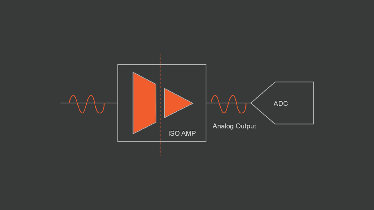
Isolated amplifiers
This “worry-free solution” provides galvanic isolation and differential input at the same time. With the isolated Dewesoft data acquisition devices, both the sensor signal and the power supply (including sensor excitation) are optically isolated.
There are several approaches for creating an isolation barrier between a signal source and the rest of the system:
Optical isolation
Inductive isolation
Capacitive isolation
Learn more details about each isolation technique:
Isolated amplifier’s inputs “float” above the common-mode voltage. They are designed with an isolation barrier with a breakdown voltage of 1000 volts or more. This allows them to reject very high CMV noise and eliminate ground loops.
These amplifiers are the perfect solution for channel-to-channel and channel-to-ground isolation. They cope with differences in ground voltage up to 1000 V, which covers all industrial applications.

The most common measurement faults
Common-mode voltage
Common-mode voltages are unwanted signals that get into the measurement chain, usually from the cable connecting a sensor to the measuring system. Sometimes referred to as “noise” these voltages distort the real signal that we’re trying to measure. Depending on their amplitude, they can range from being a “minor annoyance” to completely obscuring the real signal and destroying the measurement.
Thermocouple measurement (AC common mode)
When the common-mode voltage amplitude exceeds the amplifier’s common-mode voltage input range, the amplifier starts “clipping”, resulting in a distorted, unusable output signal.


With the use of an isolated amplifier, the measurement can be done, even if there is a high common-mode.


Current measurement with a shunt on the positive line (DC common mode)
The measurement configuration below shows the one way to measure the current of a 24 V power supply system. The optimum amplifier input range, in this case, is 500 mV. That will work fine for Ch 2 in the picture, but not for Ch 1. This channel will exceed the maximum common-mode voltage and clip.


Common-mode rejection ratio
The Common Mode Rejection Ratio (CMRR) specifies how well an amplifier can suppress unwanted equal (non-differential) signals on the input. For example, if you measure a static signal, the DC common mode will affect the accuracy, while the AC common mode will result in noise.
Ground loops with sensor
Noise in the measurement data is often caused by “ground loops”. There are various ways to create ground loops. Some of them can be very harmful to the measurement instrument and can even destroy your electronics.


In the picture above:
The measurement amplifier is connected to the ground (GND 1) on one side. An asymmetrical shielded cable is used to connect the sensor.
The metallic housing is placed on a conductive ground (GND 2).
Due to the length of the cable, there is already a difference in the ground levels, which acts like a voltage source that couples with electromagnetic noise.
Question: How big does the error have to be, to be significant?
It depends on the situation. For example, when connecting a charge or IEPE sensor with a high dynamic output of 140 dB to the amplifier that is set to a 10 V input range, the allowed potential difference would be only 1 µV!
The correct solution would be to isolate the sensor or the signal amplifier.

Ground loops with power supply
Ground loops can also be created by non-isolated power supplies. Care must be taken when supplying multiple devices, even if each device itself has good over-voltage and reverse polarity protection like Dewesoft DAQ systems.
Check out Dewesoft's fully channel-to-channel isolated modern, digital data acquisition systems


The schematic below shows this typical configuration. The sensor and DAQ system is supplied by the same DC power supply (e.g. the vehicle’s onboard power).
You can see that the ground (GND) is connected at two points. The main current flows along the blue thick line (the “high current path”) to the load and back. But the GND of both devices is also connected together, through the sensor output and DAQ input.


Important! Error case with broken GND cable
You can imagine what will happen when the “high-current path” is open: the current will flow in a different way. Now the return supply path of the sensor is routed through the GND of the sensor input from the DAQ device.


Usually, the internal circuitry is not capable of driving this high current. With this, the data acquisition device may be damaged. With an isolated power supply, no error current will be conducted through the supply line.
Conclusion
So when it comes to signal to the condition we have two practical types of signal conditioning amplifiers to choose from:
Isolated signal conditioning amplifiers
Combined isolated and differential amplifiers are more expensive than non-isolated or single-ended, but they provide a “worry-free” measurement solution. They also offer an inexperienced engineer be able to make correct and accurate measurements and keep the measurement equipment - and the human operators - safe.
Differential signal conditioning amplifiers
This type of amplifier technology is cheaper to produce and is fine when using isolated sensors like strain gauges, current clamps, acceleration, and pressure sensors. These amplifiers also deliver high-quality measurement results, but engineers need to make sure that the signal stays within the common-mode capabilities of the amplifier, and ensure that the cabling is perfect to guarantee correct measurements.
Learn more:


