


Lift Capacity Measurement on a Compact Excavator

Carsten Frederiksen & Tomáš Nedbálek (engineer test leader)
Doosan Bobcat EMEA s.r.o.
October 26, 2020
On a typical job site, excavators may be used to lift, move, and place a range of materials. Manufacturers test excavators to determine how much weight they can safely lift at various heights and distances from the centerline of the machine.
Based on these tests, they create lift charts, which are printed in the machine’s Operation and Maintenance Manual and posted within sight of the operator. Using a Dewesoft DAQ solution Doosan Bobcat has shorted the evaluation time – and now one person in the mini Excavator can operate the complete test.
Introduction
Bobcat is almost synonymous with small compact loaders, excavators, and tractors. The Bobcat Company leads the industry in the designing and manufacturing of compact equipment for construction, landscaping, agriculture, grounds maintenance, industry, and mining.


Having started in North Dakota, USA, in 1947, Bobcat today is a part of Doosan Company, a global leader in construction equipment, power and water solutions, engines, and engineering.
The Bobcat manufacturing facilities are located in the USA, China, and the Czech Republic. The headquarters of Bobcat EMEA (Europe, Middle East, and Africa) is located within a modern campus in Dobris, Czech Republic including a manufacturing plant, innovation center, and training center (Bobcat institute) within the compound.
Lift capacity measurement was done according to the ISO 10597. The results of the measurements are the machine's table of limits which is available to its customers for safety reasons. Limits can be stability or hydraulic.
The machine table consists of height and radius in given machine positions and regarding rated lift capacity limit. Machine positions are:
Over Blade with Blade Down,
Over Blade with Blade Up, and
Over Side with Blade Up.
The height and radius raster has a 1-meter step with adding maximum radius in each height.
By this short info, you can imagine how many points need to be set up and measured. Every point measurement is repeated three times.


The first problem was the long time spent with data evaluation after the measurement. Depending on the machine size it takes from 1 to 2 days. If the incorrect data were found during the post-process it was necessary to repeat measurement in the position.
The second problem was that during the lift point setup Test Engineer was operating on the edge of the 7m depth pit. This is a high-risk operation that needs to be eliminated.
These two issues have been eliminated within the last 2 years.
A challenge and the solution
The first challenge was to shorten the post-processing time after the Lift capacity measurement to check the data.
The tip was to use the Dewesoft Excel add-on. To be able to find the lift capacity also the measurement setup needs to be prepared. To be able to use the Excel table the Setup consists of:
Multiple IF statements, and
Data Header consists of the main info about the machine's position, height, radius, limit, etc.


The data header is set up for detailed info before each lift point measurement. Right after each measurement, the Test Engineer fills in the Function Limit which was reached.
For hydraulic limitation operators also fill in which function (cylinder) reaches the limit and the Excel table should look at the max pressure on this function to find related lift capacity (force/weight). For Stability measurement (also called Tipping) we set the method to tipping and the Excel table looks for max force (weight).
To be sure that the force is the maximum one, two IF statements - blocks of code to be executed if a condition is true - were added to the measurement setup.
The first IF is checking if the actual force is lower than the previous one. For this first IF the running average was calculated, to be sure that the 10 samples show decreasing force. The second IF only indicates that the force is decreasing. If both IFs are true, the measurement is ended.
These two IFs caused little trouble before the loading of the machine. Sometimes happened that both conditions were true even if nothing was happening. So, the triggered start and stop of the measurement were added.


The final step after the measurement was to open the Excel Template and Open all data and run the script.


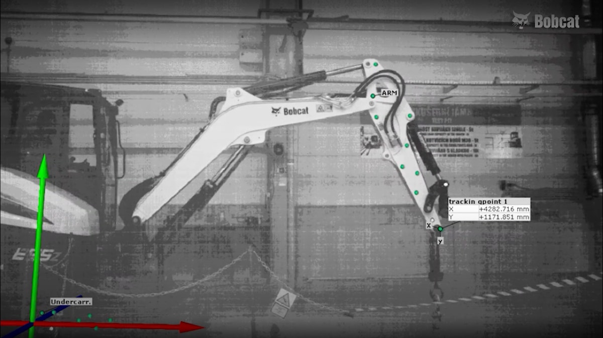
The second problem we faced was that the Test Engineer during the Lift Point position setup was standing next to the 7m deep pit. He was manually navigating the operator to reach the right lift point position and preparing the Header. For easier tracking of the lift point position, we used the GOM Aramis device.
Thanks to the Dewesoft Analog Input we were able to connect the GOM and Dewesoft together. Signals of the X and Y positions were set from 0-5V against 0 to 5000mm (for this measurement).
Now the Dewesoft measurement data file contains all-important values such as:
working pressures,
force (lift weight, operating weight), and
position of the lift point (Height and Radius).
Thanks to the cooperation of these two devices we no longer need two people to be involved in this measurement all the time.
Used measurement devices and software:
Dewesoft SIRIUS data acquisition system with STG+ type amplifiers (full-bridge, half-bridge, and quarter-bridge strain gauge sensors)
Omega Pressure sensors
Honeywell Load Cell
GOM Aramis
MS Excel 64bit
Lightweight Operator
Conclusion
In conclusion, the Dewesoft data acquisition solutions help us with shortening the evaluation time with Excel Addon, and with connection to the GOM Aramis, we have live data of the lift point.
The result is that only one person sitting in the Excavator can operate and execute the complete test.