


Sound and Noise Measurement with Microphone Transducers

January 6, 2022
In this article we will cover the topic in enough depth that you will:
Understand what sound and noise are
Learn about the different types of microphones and how they work
See how important sound and noise measurement really is
As with all of these articles, we will start with the fundamentals, and work our way through the technology of performing the essential measurements using best practices.
What is sound?
Sound is variations in pressure that the human ear can perceive. Sound can be conducted through the air, underwater, or even through solid objects. Music, speech, a running engine, a bird calling - these are all everyday examples of sound. Because of how it is created, we commonly refer to sound as sound pressure.
Sound cannot propagate without a medium. It propagates through compressible media such as air and water as longitudinal waves. In solids, it propagates as transverse waves. Sound waves are generated by a sound source (vibrating diaphragm or a loudspeaker). A sound source creates vibrations in the surrounding medium. As the source continues to vibrate the medium, the vibrations propagate away from the source at the speed of sound, forming a sound wave.
Sound pressure level (SPL) is a logarithmic measure of the effective sound pressure of a sound relative to a reference value. It is measured in decibels (dB) above a standard reference level. The standard reference sound pressure in air or other gases is 20 µPa, which is usually considered the threshold of human hearing (at 1 kHz). The following equation shows us how to calculate the Sound Pressure level (Lp) in decibels [dB] from sound pressure (P) in Pascal [Pa].
Where:
is the reference sound pressure and \(P_{rms} is the RMS sound pressure being measured.
What is noise?
It is critical that we measure and analyze not only “good” sounds, but the unwanted ones, too. Noise can be described therefore as an “unwanted sound.” As with sound in general, noise is measured in Pascals, although it is more commonly converted to the decibel scale for the sake of practicality.
Perhaps you know the acronym NVH, which stands for noise, vibration, and harshness. NVH testing is the practice of measuring unwanted sounds from a wide variety of sources so that they can be reduced or eliminated. Nearly every machine makes some kind of noise, from automobiles to leaf blowers, hairdryers, food mixers, and so on.
Designing machines to limit or improve the noise that they create is a driving force behind sound and noise measurement. Besides being an annoyance or distraction, certain sounds can be painful or even harmful, therefore they must be reduced or eliminated. The first step in any remedy is making objective measurements that can be acted upon.
How is sound measured?
The principal sensor used in sound measurement is the microphone. Microphones are used to measure sound pressure waves at a variety of frequencies, including the entire range of human hearing and even beyond. Most microphones are designed to measure sound propagating through the air, but there are other types that are meant to measure sound underwater (hydrophones), or in the earth (seismic instruments).


Sound pressure is measured in Pascals (Pa). It represents how sound is perceived by the receiver, e.g., the human ear. Many variables affect how we perceive a given sound, such as the reflectiveness of the room, the size of the room (if any), distance from the source, and more.
Learn more:

What is sound power?
Sound power is measured in watts (W). It represents the sound energy that the source is creating. It is completely independent of how the sound is perceived by the receiver.
Producers of almost any kind of machinery or devices are required by regulations, such as the Noise and Machinery Directive of the European Union (EU) (2006/42/EC), to measure and declare the sound power of their products. Everything from toys to printers, industrial tools, and construction machinery is included. Sound power measurements are also used in engineering tasks such as product sound design.


Relevant sound power standards include:
ISO 3741
ISO 3743-1
ISO 3743-2
ISO 3744
ISO 3745
ISO 639-3
ISO 639-4
ISO 639-5
ISO 639-6
To summarize, while sound pressure describes the listener’s perception of a given sound based on the acoustic environment, sound power describes the energy of the sound itself, regardless of the environment or how the sound is perceived. These terms have very different meanings and should not be used interchangeably.
In short, sound power is the cause, while sound pressure is the effect that we perceive.
Learn more:


What is sound intensity?


Sound intensity is not the same as sound pressure. It is defined as the power carried by sound waves per unit area in a direction perpendicular to that area. Sound intensity is defined as sound pressure ( \(Pa\)) multiplied by particle velocity ( ).
where is sound pressure in pascals and v is particle velocity in meters per second.
The intensity of sound is an important measurement. In effect, it is the time-averaged rate of energy flow per unit area. Unlike many sound power tests that require a controlled environment like an anechoic chamber, sound intensity measurements can be made anywhere.
Learn more:


What is Sound Exposure Level?


Sound exposure level is a measurement of both the level of sound received and the duration of that exposure. The duration is critical because people can withstand certain frequencies and amplitudes for a short time, but longer noise exposures can lead to hearing damage or even hearing loss. Sounds at 90 dB and above are considered harmful to human beings.
is the integral (over time) of sound pressure squared. The SI unit is defined as:
(Pascal squared second)
What is sound level?
Sound level is a general term that may include one or more of the specific ways that we measure sound, including:
Sound Pressure Level
Sound Intensity Level
Sound Power Level
Sound Exposure Level
Sound level is usually measured with a device called a sound level meter (or just a sound meter). Please refer to each of those quantities as described in this article for specific information about them.
What is sound quality?
Sound quality measurement provides an objective evaluation of how sounds produced by machines are perceived by the human ear. With these measurements, engineers can improve and refine the sounds generated by their machines in order to create products that are more pleasing to the user and others around them.

Although the human perception of sound is subjective, it is possible to make objective measurements of sound and then apply a range of sound quality metrics to them, including:
| Loudness | Calculation according to ISO 532-1 and ISO 532-2: Acoustics - Methods for calculating loudness - Zwicker method and Moore-Glasberg method. The loudness of sound is measured in decibels (dB). |
| Sharpness | Calculated from specific loudness, which is determined according to ISO 532-1 and ISO 532-2 standards. Sharpness is a psychoacoustics metric that provides a numerical measure of sensation based on the number of high-frequency components in a sound. Its unit is the “acum”, where 1 acum corresponds to the sharpness of a broad-band noise centered on 1 kHz, with a width of 1 critical band and a level of 60 dB. |
| Noise Criterion (NC) | A metric used in the USA for rating indoor noise sources |
| Noise Rating (RC) | A metric used in Europe for rating indoor noise sources |
| Speech Intelligibility | A metric for the evaluation of speech perception |
| Articulation Index, extended | An extension of speech perception when other sounds are present |
| Normal equal-loudness level contours | Calculation according to and based on the ISO 226 standard |
| Prominence ration | Calculation in accordance with ISO 7779 - measurement of airborne noise emitted by information technology and telecommunications equipment. |
Sound quality testing is important for companies that want to evaluate and improve the sound of their products. The goal is to make them more desirable to the user by controlling the way that they sound. The testing is applied in:
Automotive Noise, Vibration and Harshness (NVH), automotive designs and components
Audio devices including loudspeakers, microphones, amplifiers, headphones, musical instruments
Household and garden appliances, e.g., lawnmowers, dishwashers, refrigerators, computers, HVAC systems
It is used by R&D departments for:
Benchmarking and Improvement
Target Setting
Modeling and Simulation
Predictions
Reactive Engineering
Testing and Troubleshooting
Product Validation
Learn more:

How to measure sound frequency?
One of the most fundamental and powerful ways to measure the frequencies contained in sound is the Fast Fourier Transform, abbreviated as FFT. The FFT is a set of algorithms that convert time domain data into frequency domain data. DAQ systems typically record sound and noise data from microphones, then software performs the conversion from the time domain to the frequency domain. This conversion can be done in real-time, or as a post-processing function.
Using FFT analysis, numerous signal characteristics can be investigated to a much greater extent than when inspecting the time domain data. In the frequency domain, signal characteristics are described by independent frequency components, whereas in the time domain it is described by one waveform, containing the sum of all characteristics.

 is converted via FFT algorithms to the frequency domain (right).")
In a typical time-domain graph, the vertical axis is the amplitude of the signal, and the horizontal axis is time - thus, we can see how a signal’s amplitude changes over time.
Time-domain graphs are essential and useful for thousands of applications, but they don’t tell us much about the specific frequencies contained within complex signals. Using FFT conversion, however, we convert the signal so that the vertical axis shows magnitude, and the horizontal axis shows frequency instead of time. As such, frequency becomes the domain that we are working in.
Referring to the FFT graph below, you can see that the frequency axis is scaled from 0 Hz to 10 kHz from left to right. There is a very large magnitude spike at 1200 Hz, and a smaller frequency spike at around 3750 Hz.
The classic FFT graph is an essential tool in frequency measurement and is widely used. In most DAQ systems that are suited for sound measurements, either or both of these axes can be scaled as linear (as shown below) or logarithmic, which can provide more important information based on the application.


Since time is not represented on this classic FFT graph, the data necessarily represents one moment in time. But which moment and how much time? Basically, FFT analysis involves taking a slice of time (x number of samples at y sample rate), performing the calculations, and then displaying it. This is called the “window time,” and it can be controlled by the engineer or technician operating the analyzer, as well as the basic capabilities of the analyzer.
DAQ systems like the ones made by Dewesoft include powerful FFT analysis tools built directly into the software. Cursors, including harmonic cursors, can be used on the graphs to directly click on peaks and spikes, and read out their exact values. Math channels can also be displayed that show the peak values automatically.
Note that it is also possible to present TIME on an FFT graph, by adding a third axis. This 3D display, also known as a “waterfall display,” plots frequency and magnitude, and time, using color coding for easy visual interpretation.


There are many aspects of FFT analysis, and it is well beyond the scope of this article to cover them. These include Spectral Resolution, Amplitude Scaling, Time Weighting Windows, Averaging, Overlap, and more. Please refer to the informative article below to learn more about FFT frequency analysis.
Learn more:


What is a microphone?
Beyond their obvious entertainment and public speaking applications, microphones are real sensors that are heavily used in scientific and industrial measurement applications. Simply put, a microphone is a sensor or transducer that converts sound (acoustic energy) into electrical energy that we can amplify, digitize, display, record, and more.
As with other sensors, there are several types of microphones that are commonly used in sound and noise-measuring applications. This is because there are so many different applications and environments in this very broad field, as we will describe in this article. Reacting to demands from engineers involved in sound testing, microphone manufacturers have created a wide range of microphones designed to address these applications.
Microphones used for scientific or industrial sound measurement are also referred to as microphone sensors or microphone transducers.
How do microphones work?
A microphone is a transducer that converts sound energy into electrical energy. There are several kinds of microphones, and they work in different ways. But we should start with the classic dynamic microphone invented more than 100 years ago.


A diaphragm made of thin material like plastic resonates in response to the incoming sound pressure waves.
A coil attached to the diaphragm moves back and forth in sympathy
A permanent magnetic creates a magnetic field that is induced into the coil
This current is an “analog” of the sound. It flows out of the coil and can be amplified, converted to digital, recorded for display and analysis, etc.
The kind of microphone transducer described above is typically referred to as a dynamic microphone. Note that if you reversed this transducer by inputting an electrical signal at its output, the coil would move and drive the diaphragm. And if you made the diaphragm much larger, it would move the air and create sound. Congratulations, you just built a loudspeaker… it’s simply a dynamic microphone in reverse!
What are the most important microphone technologies?


The three most essential technologies behind microphones today are:
Dynamic mics are based on magnetic induction, where a moving coil connected to a diaphragm and wrapped around a permanent magnet converts sound pressure into an electrical signal. A variation is the ribbon mic, which employs a thin metal ribbon as the diaphragm and transducer. Dynamic mics are used primarily in music, entertainment, broadcast, and public address applications.
Condenser mics are based on capacitance. A diaphragm with a charge plate behind it outputs an electrical charge in response to sound pressure waves. Heavily used in sound measurement and scientific applications.
Piezoelectric mics are also based on capacitance, but they use a crystalline material instead of a charged plate. Also heavily used in sound measurement and scientific applications.
Since they are so important in sound measuring and scientific applications, we will focus on condenser and piezoelectric mics in this article.
Condenser microphones
One of the most popular microphones for sound measurement is the condenser type. These mics are designed around a thin metal diaphragm next to a metal backplate. When sound pressure pushes against them, the capacitance between the diaphragm and the backplate changes. This change in capacitance is output as an AC signal that we can amplify, measure, digitize and analyze.


Condenser microphones require power to generate a charge for the diaphragm and plate. This can be done in one of two ways, depending on the microphone that you select:
Externally polarized microphones require a 200V supply from an external microphone power supply. Normally a 7-pin LEMO or similar connector is used to make the required connections.
Prepolarized microphones do not require a 200 V supply. Also referred to as electret microphones, they are permanently polarized by means of a permanently charged dielectric material, either used as the diaphragm itself or located elsewhere within the capsule. They do, however, require a constant current supply like the one required by a typical IEPE accelerometer, sometimes referred to as “phantom power.” Because this DC current can be carried on the signal line without interference, these mics require only a 2-pin connector, usually a BNC.
Condenser microphones are available in a variety of sizes, 1 inch, ½ inch, ¼ inch, or ⅛ inch diameters. Larger mics can be more sensitive, and thus measure lower frequency signals than smaller diameter microphones.
Piezoelectric microphones
Piezoelectric microphones work much like piezoelectric (IEPE) accelerometers. They operate on the principle that certain crystalline materials, such as quartz, output a variable charge when they are mechanically stressed, either by acceleration or, in this case, sound pressure. A tiny internal amplifier converts this charge signal into a higher level voltage that is output to an IEPE signal conditioner.


IEPE signal conditioners provide the constant current supply that is needed to power the tiny amplifier within the piezoelectric microphones.
Which is better, condenser or piezoelectric microphones?
Condenser and piezoelectric microphones serve different functions. For example, condenser mics have a much lower noise floor than piezoelectric mics. But on the other hand, piezoelectric mics can withstand higher pressure levels than condenser mics, so they can be used in blast tests and other high-amplitude sound and noise applications. Neither technology is “better” per se - they have different roles.
| Condenser Mics | Piezoelectric Mics | ||
|---|---|---|---|
| Prepolarized | Ext. Polarized | ||
| Dynamic range | Excellent | Excellent | Good |
| High amplitude operation (shock, blast applications) | Good | Good | Excellent |
| High-temperature applications | Good | Superior | Good |
| High humidity applications | Superior | Good | Good |
| Connectivity | IEPE 2-wire connection, BNC connector | 7-wire connection, external 200V supply required, LEMO | IEPE 2-wire connection, BNC connector |
| Cost | Lower cost than externally polarized | Higher cost than pre-polarized | Similar to pre-polarized condensers |
Special microphone types
Hydrophones


You would not take a normal microphone and drop it into the water because it will be damaged or destroyed. For underwater applications, manufacturers offer specialized microphones called “hydrophones.” These corrosion-resistant mics are designed to be submerged permanently in water and are used for a wide variety of industrial, scientific, and military applications.
Sound pressure waves travel 4.3 times faster in water than they do in the air. And because water is much denser than air, a given sound exerts many times as much pressure in water as it would in air. Hydrophones are specially designed to operate in this medium.
Hydrophones are available in unidirectional and omnidirectional models. It is also possible to use them in arrays for a variety of applications, including beamforming, a spatial filtering technique.
Since the pressure underwater increases the deeper you go, always check that a hydrophone has been designed for the depth that you require.
Array microphones


As the name implies, array microphones (aka “microphone arrays”) consist of multiple mics arranged in a pattern. They are intended to make 3-dimensional measurements of sound. Array mic systems may consist of anywhere from 2 mics used to detect leaks in hearing aids, to more than 100 mics used for beamforming and acoustic holography applications.
Array microphone systems are used for a variety of applications, including:
Wind turbine sound test
Automotive and train pass-by tests
Factory sound emissions
Holography
Automotive and aircraft interior tests
Engine noise tests
Sound pressure mapping
Beamforming
Medical device noise tests
Wind tunnel testing of cars, aircraft, etc.
MEMS microphones
If you’re reading this article on a notebook computer, tablet or smartphone, chances are very good that there is a MEMS microphone built into it. Taking advantage of MEMS technology (micro-electromechanical system). MEMS microphones can be machined smaller than 3 x 2 x 1 mm. In English, units are only about 1/8 inch at their widest point.
Most MEMS mics consist of a pressure-sensitive diaphragm that has been etched directly into the silicon. They often have an integrated preamp, and often include an ADC that converts analog sound into a digital data stream. Although MEMS mics were primarily condenser types since their invention, piezoelectric models are now also available.
In addition to computers, phones, and tablets, MEMS microphones are also used in wearable electronics, drones, internet of things (IoT) devices, smart television remote controls, and more.
Sound intensity probes
Intensity probes are microphones that are used to measure the intensity of sound, as defined earlier.


Most sound intensity probes use a pair of phase-matched free-field microphones to measure both the instantaneous pressure and the pressure gradient of the sound field. They are often provided on poles that allow the system to be aimed at the sound source. Moving the system allows for sound intensity mapping applications, sound power measurement, and IEC 61043 and IS0 9614-1 standard measurement.
How to choose the right microphone
As with any other sensor, choosing the right microphone is determined by the application. In sound measuring applications, the environment is often a driving factor in microphone selection and setup.
The measuring environment is often referred to as the response field. When you hear microphones being referred to as “free field” or “pressure field” types, this refers to the response field that they will be used in. We will describe what this means below.
In addition to selecting a mic that has been designed for your target measuring environment, you also need to consider the bandwidth and the maximum SPL (sound pressure level) that the mic will need to support.
If your measuring environment is either very hot or cold or experiences high humidity levels, you should also check those specifications in any microphones and their signal conditioners that you intend to use. As a general statement, condenser mics are more adversely affected by high temperature and humidity environments than piezoelectric mics. However, some manufacturers offer condenser mics specifically made for challenging environments.
Free-field microphones
Free-field microphones are meant to be used in reflection-free environments, such as outdoors, or in anechoic chambers. They are designed to measure sound pressure variations that move freely through the air, usually from a single source. Free-field mics are usually pointed directly at the sound source.
Free-field mics are intended to measure the sound pressure as if the microphone itself was not present within the field. Of course, any physical object within the field can disturb it - this can occur when sound frequency wavelengths approach the dimensions of the mic itself. As a result, manufacturers typically add microphone calibration correction values to compensate for any disturbance that the mic itself may cause within the sound field.


Free-field testing applications include:
Automotive pass-by and other outdoor noise levels tests
Loudspeaker test
Appliance testing in suitable chambers, including washing machines, dishwashers, blenders, and other consumer goods
Operation troubleshooting to eliminate excess vibration or noise
Outdoor noise monitoring
Pressure-field microphones
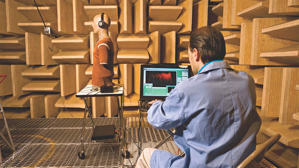
Pressure-field mics are meant to measure the sound pressure on the microphone’s diaphragm. Sometimes these mics are placed directly on a wall, coupler, or on the internal surface of a chamber or closed area so that they can measure the sound pressure on the wall or surface. They are found in nearly all ear simulator testing applications.


Pressure-field mics are typically designed to have a very flat frequency response. As a result, they are sometimes often used in random incidence applications as described below, when this flat response is required.
Pressure-field testing applications include:
Human ear simulation tests
Measuring the sound pressure on aircraft fuselages
Measuring the sound pressure on walls and cavities
Measuring the sound pressure inside tubes and other structures
Random incidence microphones
Random incidence (aka “diffuse field”) omnidirectional microphones are made for environments where sound may come from any or all directions. These include highly reflective environments, reverb chambers, and the like. These mics are designed to respond uniformly to sound pressure arriving from all directions at the same time.

Pressure-field testing applications include:
Room, auditorium, theater acoustics
Automotive passenger cabin noise tests
Aircraft passenger cabin noise tests
Household appliance testing
Environmental noise testing
Good for mid and high amplitude sound environments
Key microphone specifications
Dynamic response
A normal human ear can hear sound down to 20 millionths of one Pascal. Since this scale isn’t very practical for everyday use, and because human hearing is logarithmic in nature, most engineers and scientists use the decibel (dB) scale.
| Pascal value | Decibel (dB) value | |
|---|---|---|
| Threshold of human hearing | 0.00002 Pa | 0 dB |
| Typical office ambient noise | 0.02 Pa | 60 dB |
| Typical factory ambient noise | 0.2 Pa | 80 dB |
| Jackhammer in operation | 2 Pa | 100 dB |
| Jet engine take-off | 20 Pa | 120 dB |
| Threshold of pain | 200 Pa | 140 dB |
The decibel scale (dB) was named for Scottish scientist Alexander Graham Bell, inventor of the telephone and audiometer.
Microphones are rated according to the maximum pressure level that they can withstand before either the diaphragm comes into contact with the plate, or when total harmonic distortion (THD) reaches a specified value, like 3% for example.
Manufacturers also often specify the smallest sound that the mic can detect. Sometimes called the cartridge thermal noise (CTN), this specifies the smallest sound that the mic can detect above the electrical noise of its circuitry.
Larger diaphragm mics typically have lower noise floors (CTN) than smaller diaphragm mics.
Frequency response
Bandwidth is always an important consideration when it comes to any sensor or transducer. The usable bandwidth, or frequency response, of a sound sensor (microphone) is measured between its CTN and maximum rated sound pressure level. When looking at a mic’s spec sheet, pay attention to the tolerance in addition to the frequency response itself. Tolerance will normally be expressed in decibels, like ±2 dB, or similar.
Signal to noise ratio
The ratio of the wanted sound energy to the unwanted sound energy is known as the signal-to-noise ratio (SNR). SNR is expressed in dB. An SNR ratio is greater than 1:1 means that there is more signal than noise power present.
SNR = Psignal / Pnoise
Where:
P = average power
Polar patterns
The polar pattern of a microphone defines how sensitive it is to sounds coming from different directions around its axis. Mics can be designed to be more sensitive to sounds coming from the front, for example, to focus only on those sounds and ignore those coming from the back or sides. The most common patterns include:
Omnidirectional microphones
Omnidirectional mics are designed to measure sound coming from all directions equally. In practical terms, this is not possible due to the physics of any mic and its own presence within the sound field, but omnidirectional mics achieve great performance and the purest possible measurement of sound pressure.


Unidirectional microphones (aka cardioid microphones)
Named after the “heart-shaped” that their polar pattern resembles, cardioid mics are meant to measure sound coming primarily from the front of the mic. There are several implementations of the cardioid pattern, including cardioid, hypercardioid, supercardioid and subcardioid. Referring to the polar pattern images below, you can see how they are designed to measure primarily from one direction, in varying degrees:


There are other patterns, including bi-directional, also known as “figure of 8,” which is used for measuring sound both in front and behind the microphone, and others.
Microphone measurement applications
There are hundreds of applications for measuring sound and noise. However, there are some very popular ones in common use across many industries. At the highest level, there is a group of tests called NVH, which stands for Noise, Vibration, and Harshness.
NVH (noise, vibration, and harshness) applications

Although NVH testing applies to a wide variety of machines, from your lawnmower to a cement mixer, NVH is most closely associated with automotive testing. If you’re familiar with driving around in an average-priced car, and then getting into a luxury model, you will undoubtedly have a very different experience. Closing the door of a luxury car seems to block out most of the sound from the outside, and the engine, despite its power, hums in a subtle and satisfying way. There are few if any rattles and squeaks.
This relatively pleasant experience is the result of countless hours of testing, design, re-testing, and re-design by a cadre of automotive engineers. Microphones and other sensors are used to measure the acoustic and conducted vibrations both inside and outside the car, both under real driving conditions and in anechoic chambers. Then automotive engineers use this data to refine vehicle design and materials until it meets their noise requirements under a variety of driving conditions.
Harshness is more subjective and difficult to quantify because it relates to how “annoying” a sound, vibration, or combination is to the average person.
There are numerous interior (inside the driving cabin) and exterior NVH tests performed on automobiles, trucks, and buses, including:
Brake Noise Testing
Automotive Pass-by Noise Testing
Engine Noise Testing
Powertrain Testing
Pass-by Noise Testing
Exhaust Noise Testing
Electric and Hybrid Vehicle Testing
Wind Noise Testing
Buzz, Squeak and Rattle Noise Testing
Vehicle Interior Noise Testing
Road Noise Testing
Noise at work & environmental noise


People’s exposure to noise at the workplace is a health issue and is therefore regulated in the USA, Europe, and elsewhere. There are sound and noise measurement applications including:
Urban Noise Testing
Workplace and Factory Noise Testing
Room Acoustics Testing
Airport Noise Testing
Musical Concert Sound Level Testing
Electro acoustics

Telephone Sound Testing - Corded, Wireless, and Hands-free
Hearing Aid Testing
Speaker and Smart Speakers Testing
Headphones Testing - Corded and Wireless
Machine analysis
When we think of predicting machine failures and diagnosing machine problems, we normally think of measuring vibrations and temperature, but noise is an important indicator of machine health. Machines that are unbalanced, for example, often exhibit this first with sound. If you’ve ever heard your clothes dryer struggling with a badly unbalanced load, you know what that sounds like.
Machine Vibration Testing
Condition Monitoring
Predictive Maintenance Testing
Air and gas leak detection
Noise source identification

Sometimes it’s not enough to simply know how much noise there is in a given place, but it is necessary to know exactly where it is coming from. Which component or system is generating the noise and why? For these applications, microphone arrays are a good solution because they can create a three-dimensional representation of an area.
Imagine a subway car passing by a microphone array. Perhaps the wheels or brakes are squealing, or the shoe is running along the third rail and making noise, or the pantograph is running along the catenary wires overhead. For moving objects, beamforming software helps to create a 3D map over time.
Sometimes referred to as “acoustic cameras,” array mic systems can be at the micro-level, as with hearing aid testing, or macro level, as with large machines (generators, cutting machines, trains, cars, aircraft) or even a whole factory.
Transportation Systems Noise Source Analysis - Airports, Metro Rail, Bus Stations
Wind Tunnel Acoustic Testing - Aerospace and Automotive
Acoustic Holography
Sound Intensity Mapping
Engine Noise Testing
Cabin Noise Testing
Hospital gas leak detection
Compressed air leak detection
Dewesoft sound measurement modules
Dewesoft offers a variety of high-end DAQ systems that are ideal for measuring sound and vibration. Here is a short overview:
SIRIUS DAQ systems


DualCoreADC series
SIRIUS® DualCoreADC® systems use two 24-bit ADCs per channel in order to achieve an incredible 160 dB dynamic range in both the time and frequency domains. Sample rates up to 200 kS/s per channel and built-in anti-aliasing filtering provide more than 70 kHz of guaranteed alias-free bandwidth. All channels are galvanically isolated, preventing common mode, noise, and ground fault problems.
High-density series
By using a single 24-bit ADC per channel, SIRIUS HD systems still offer high dynamic performance, but with twice as many channels per slice: 16 instead of 8.
High-speed series
Using 16-bit SAR ADC technology, SIRIUS HS systems provide sampling rates up to 1 MS/s per channel, and still with 8 channels per slice.
Extra high-speed series
SIRIUS XHS systems are a whole new breed of DAQ systems. Each channel can sample up to 15 MS/s. When the sample rate is 1 MS/s or below, the resolution is 24-bit. Above 1 MS/s it is 16-bit. Even more impressive is that each channel can be set to any sample rate and measurement mode, but they remain completely synchronized.
SIRIUS ACC microphone and accelerometer amplifiers
SIRIUS can be configured with a wide variety of amplifiers in order to handle virtually any signal and any sensor, so it goes well beyond sound and vibration measurements as a system. But the amplifiers used for these applications are in the ACC series.
ACC amplifiers are designed to handle IEPE sensors, including accelerometers, piezoelectric microphones, and pre-polarized condenser microphones. They provide the constant current power required by these sensors. An ACC amplifier is available for all four SIRIUS mainframe types:
| ACC Amp | SIRIUS DualCoreADC | SIRIUS HD (High Density) | SIRIUS HS (High Speed) | SIRIUS XHS (eXtra HS) |
|---|---|---|---|---|
| Connector | BNC | BNC | BNC | BNC |
| Max. channels/slice | 8 | 16 | 8 | 8 |
| Max. sample rate | 200 kS/s/ch | 200 kS/s/ch | 1 MS/s/ch | 15 MS/s/ch |
| Resolution | 24-bit | 24-bit | 16-bit | 24-bit up to 1 MS/s, then 16-bit |
| Dynamic range | -140 dB (-160 dB @ DualCore) | -137 dB (@ 10 kS/s) | -89 dB (±10V @ 100 kHz | up to 150 dB @ 1 MHz |
| Bandwidth | ~ 76 kHz | ~ 76 kHz | 500 kHz | 5 MHz |
| Voltage ranges | ±200 mV to ±10 V | |||
| Input coupling | DC or AC 0.1 Hz, 1 Hz | DC or AC 0.1 Hz, 1 Hz | DC or AC 1 Hz | DC or AC 0.1 Hz, 1 Hz |
| IEPE sensor power | 2, 4, 8, 12, 16 or 20 mA | 4, 8, or 12 mA | 4 or mA | 2, 4, 8, 12, 16 or 20 mA |
| Isolation | 1000 V | |||
| Counter option | Yes, accepts encoders, tach and pulse sensors, and more. Ideal for order tracking, torsional and rotational vibration, and more. | |||
| More functions | TEDS interface, built-in sensor databaseAutomatic sensor error detection | |||
| Sensor Compatibility | Prepolarized condenser mics, piezoelectric mics, externally polarized mics with an external power sourceIEPE accelerometers |
Note that SIRIUS ACC amplifiers are compatible with all major microphone types, including native support for prepolarized condenser, and piezoelectric microphones. Non-prepolarized condenser mics can also be used if they have an external power source. For direct support of externally polarized condenser mics, see the SIRIUS MIC200 below.
Learn more:
 system")
")
SIRIUS MIC200 system


The SIRIUS MIC200 is a high-performance 8-channel SIRIUS DAQ system that has been configured specifically for externally polarized condenser microphones. It uses 7-pin LEMO connectors to supply the 200V that externally polarized condenser mics require. SIRIUS MIC200 is designed for accurate measurement of high-amplitude signals, with high temporal and temperature stability.
SIRIUS MIC200 features
High dynamic range: DualADC technology provides a 160 dB dynamic range
Fast acquisition: 200kS/s sample rate supports high-frequency microphones
Multi-brand microphone support: Industry-standard 7-pin LEMO connector supports all major microphone brands
TEDS support: automated setup of TEDS-equipped microphones
High channel count: use as many MIC200s as required for your applications. Multiple systems are synchronized automatically
DewesoftX software included
Class 1 IEC SLM and a complete set of advanced ISO compliant measurements: Sound Power, Sound Intensity, Sound Quality, RT60
IEC acoustic calibration services: IEC61672, IEC61260, IEC 60651, IEC 61094-4, etc. and you can order everything pre-calibrated at the factory
SIRIUS MIC200 is multifunctional and extensible. It can be synchronized with any other Dewesoft DAQ system. You may simultaneously capture temperature, vibration, video, strain, and more, all under one software, with all data perfectly synchronized.
SIRIUS MINI

SIRIUS mini is a very small USB-powered DAQ system configured with four high dynamic analog inputs for direct voltage or IEPE/ICP signals. Each amplifier has two 24-bit Sigma-Delta ADCs with up to 200 kHz sampling rate per channel and built-in anti-aliasing filtering. The result is a dynamic range up to 160 dB, perfect for sound and vibration measurements.
Simply connect the SIRIUS mini to a Windows® computer and run the included DewesoftX software, and you have a powerful four-channel DAQ system for hundreds of applications in sound and vibration measurement.
Each of the four analog inputs can handle any IEPE powered condenser or piezoelectric microphone, or IEPE accelerometer. You can also use externally polarized condenser mics by powering them externally.
You will see that the input specifications are almost identical to the ACC amplifier in the SIRIUS DualCore series shown in the previous section:
| SIRIUS mini | |
|---|---|
| Connector | BNC |
| #Channels | 4 |
| Sample Rate (max.) | 200 kS/s/ch |
| Resolution | 24-bit |
| Dynamic Range | -140 dB (-160 dB @ DualCore) |
| Bandwidth | ~ 76 kHz |
| Voltage Ranges | ±500 mV or ±10 V |
| Input Coupling | DC or AC 0.1 Hz, 1 Hz |
| IEPE sensor power | 2, 4, 8, 12, 16 or 20 mA |
| Over voltage protection | In+ to In-: 50 V continuous; 200 V peak (10 ms) |
| Counter option | Yes |
| More functions | TEDS interface, built-in sensor databaseAutomatic sensor error detection |
| Sensor Compatibility | Prepolarized condenser mics, piezoelectric mics, externally polarized mics with an external power sourceIEPE accelerometers |
| Size | 146 x 139 x 64 mm (5.7 x 5.4 x 2.5 in.) |
| Weight | 0.74 kg (1.63 lbs) |
With the optional SuperCounter input, you can add encoders and tacho sensors for doing order tracking on rotating machines and more.
SIRIUS mini is powered by your notebook computer and easily fits in a backpack.
Learn more:

DEWE-43A
The DEWE-43A is a small USB-powered DAQ system configured with eight universal analog inputs, eight SuperCounters, and two CAN BUS interfaces.


Each amplifier has a 24-bit Sigma-Delta ADC with up to 200 kHz sampling rate per channel and built-in anti-aliasing filtering. Each of the analog inputs can directly measure voltage or full-bridge sensors. But it becomes a sound and acceleration measuring tool when you plug tiny DSI-ACC adapters into the analog inputs. The DSI-ACC adapters allow the direct connection of IEPE mics and accelerometers.

Simply connect the DEWE-43A to a Windows® computer and run the included DewesoftX software, and you have a powerful 8-channel DAQ system for hundreds of applications in sound and vibration measurement … and more.
Configured with a DSI-ACC adapter, each analog input can handle any IEPE powered condenser or piezoelectric microphone, or IEPE accelerometer. You can also use externally polarized condenser mics by powering them externally. By using the DSI-CHG adapter you can connect charge accelerometers. There are other DSI adapters for other sensors, including LVDTs, current, voltages up to ±200, and more.
Here are the DEWE-43A specifications with DSI-ACC adapters:
| DEWE-43A with DSI-ACC adapter | |
|---|---|
| Connector | BNC |
| #channels | Up to 8 |
| Sample rate (max.) | 200 kS/s/ch |
| Resolution | 24-bit |
| Signal-to-noise ratio | 0.1 kS/s to 51.2 kS/s: 105 dB51.2 kS/s to 102.4 kS/s: 100 dB102.4 kS/s to 200 kS/s: 75 dB |
| Bandwidth | ~ 76 kHz |
| Voltage ranges | ±10 mV, ±100 mV, ±1 V, ±10 V |
| IEPE sensor power | 20 mA |
| Over voltage protection | ±70 V |
| Counters | 8 isolated SuperCounters built-in |
| CAN BUS | 2 isolated CAN BUS interfaces built-in |
| More functions | TEDS interface for DSI identification, built-in sensor database |
| Sensor compatibility | Prepolarized condenser mics, piezoelectric mics, externally polarized mics with the external power sourceIEPE accelerometers |
| Size | 225 x 80 x 45 mm (8.8 x 3.1 x 1.7 in.) |
| Weight | 0.72 kg (1.59 lbs) |
By using any of the eight included SuperCounter inputs you can add encoders and tacho sensors for doing order tracking on rotating machines and more.
DEWE-43 is powered from a wide-range DC power and includes an AC/DC adapter. You can fit several of them in any backpack.
Learn more:

KRYPTON series

KRYPTON is an extremely rugged DAQ series that can be used outdoors and in extreme environments. They’re waterproof, operate in extreme temperatures, and withstand heavy shock and vibration. There are both single-channel and multi-channel KRYPTON modules available. Modules are interconnected using EtherCAT cables, which carry power, timing, and the digitized data back to a host computer running the included DewesoftX DAQ software

KRYPTON ACC series modules are available for IEPE powered condenser or piezoelectric microphones, or IEPE accelerometers. You can also use externally polarized condenser mics by powering them externally. Each amplifier has a 24-bit Sigma-Delta ADC and built-in anti-aliasing filtering.
Here are the specifications when using single or multi-channel KRYPTON ACC amplifiers:
| KRYPTON 4xACC | KRYPTON 8xACC | KRYPTON 1xACC | |
|---|---|---|---|
| Connector | BNC | ||
| #channels | 4 | 8 | 1 |
| Max. sample rate | 20 kS/s/ch | 40 kS/s | |
| Resolution | 24-bit | ||
| Dynamic range | Typical Dynamic Range @ 10 kS/sec:-140 dB @ ±10 V-134 dB @ ±200 mV | Typ. SFDR (10 kS/sec, -1 dBFS sine wave @ 1 kHz):-113 dB @ ±10 V-106 dB @ ±200 mV | |
| Bandwidth | 0.49 fs (alias-free bandwidth: 0.453 fs) | ||
| Voltage ranges | ±10 V, ±5 V, ±1 V, ±200 mV | ||
| Input coupling | DC, AC 0.1 Hz, 1 Hz | ||
| IEPE sensor power | 4 or 8 mA | ||
| Input protection | In+ to In-: 50 V continuous, 200 V peak (10 ms) | In+ to In-: 50 V continuous, 200 V peak (10 ms) and 125 Vrms channel to ground isolation | |
| Dimensions | 213 x 39 x 56 mm | 213 x 54 x 56 mm | 62 x 56 x 29 mm |
| More functions | TEDS interface for DSI identification, built-in sensor database | ||
| Sensor Compatibility | Prepolarized condenser mics, piezoelectric mics, externally polarized mics with an external power sourceIEPE accelerometers |
Note: KRYPTON-1xACC can sample at 50 kHz if it is the only module in the EtherCAT chain. This feature is useful for the microphone measurements where a 50 kHz sampling rate is required.
Learn more:
 systems")
Sound measurement and sound analysis software
DewesoftX DAQ software can handle a variety of acoustic, sound and noise measurement applications, including sound power, sound intensity, sound quality, and more. Here is a short overview of these turn-key software solutions:
Sound level meter


This DewesoftX software add-on is an IEC 61672 Class 1 sound level meter. It makes IEC 60651, IEC 60804 measurements in both air and water. Acoustic measurements can be combined with all other physical measurement parameters, vehicle bus systems, video, GPS, and other math to build a thorough image of your entire measurement.
Predefined standard frequency weighting A, B, C, D, and Z), time weighting (Fast, Slow or Impulse), sound pressure level, equivalent, peak, minimum and maximum sound pressure levels, sound energy, impulsivity of sound, statistical noise level (LAF1, 5, 10, 50, 90, 95 and 99 % classes of values) are all available at the same time.
Flexible displays offering digital meters, analog bars, time-domain recorders, narrowband FFT, and octave analyzers can be freely combined to show your SLM data in real-time as well as in post-processing.
Learn more:
Sound power
This DewesoftX software add-on is fully compliant with relevant sound power standards ISO 3741, ISO 3743-1, ISO 3743-2, ISO 3744, ISO 3745, ISO 6393, ISO 6394, ISO 6395, ISO 6396.
The software steps the user through the entire measurement, including entering all relevant parameters regarding the positions of the mics around the hemisphere (according to standards), microphone calibration, and more.
After the test, the software allows the test operator to generate a standardized Microsoft Excel® report document with just a few clicks.
All calculated parameters are available during measurement as well as offline; rapid calculation of correction factors K1 (background noise measurement), K2 (room correction with integrated RT60 module), C1, C2 and C3 (deviations due to variations in temperature and barometric pressure); support for raw time-domain data storing and offline sound power calculation.
Learn more:
Sound quality


Sound quality measurement is an indispensable tool. These measurements address the need to empirically evaluate how sound produced by different kinds of machines are perceived by the human ear.
A variety of sound quality tests are handled by the software, including:
Loudness calculation according to ISO 532-1 and ISO 532-2: Acoustics - Methods for calculating loudness - Zwicker method and Moore-Glasberg method
Normal equal loudness contours calculation according to (and based on) the ISO 226 standard
Sharpness is calculated from specific loudness, which is determined according to ISO 532-1 and ISO 532-2 standards
Speech intelligibility and extended articulation measurements of perception while other sounds are present
Noise criterion (USA) and Noise Rating (EU) tests
Prominence ratio calculation in accordance with ISO 7779 - measurement of airborne noise emitted by information technology and telecommunications equipment.
And more…
But perhaps the most important thing to know is that, unlike a dedicated sound quality meter, Dewesoft systems can measure anything. They are not limited to just measuring sound. That means that you can make sound quality measurements AND measure other parameters as well, allowing you to compare the operation of the machine with the resulting sound quality.
Learn more:
Sound intensity


The DewesoftX sound intensity software add-on complies with Sound Intensity-based Sound Power calculation - Discrete points method (ISO 9614-1) and Scanning method (ISO 9614-2). It is a complete measurement solution, providing precise noise source location or sound power calculation, without the need for any special environment such as a reverberation room or anechoic chamber.
Depending on the direction of sound waves travel (from microphone A to B or vice versa), our plugin will display different values (positive or negative) as the noise source moves along the axis of the probe. When the probe is perpendicular to the noise source (located directly above it), the visual control inside Dewesoft X3 DAQ software will toggle between positive and negative values. This process is done for the horizontal and vertical alignment of the probe axis, the sound.
Learn more:
Octave band analysis

The DewesoftX octave band analysis software add-on is an indispensable tool for sound measurement. Octave band analysis provides a close approximation of how the human ear will respond to the measured sound. Dewesoft octave band analyzer meets all of the IEC and ANSI specifications for octave filters, providing true octave analysis as defined by the IEC 61260 standards. It also provides selectable synthesized octave analysis for large channel count testing applications.
Standard frequency weighting curves (A, B, C, D, and Z) can be applied directly in a frequency domain for the analysis of sound. DewesoftX provides a very narrow band analysis down to the 1/24th octave.
In octave band analysis, averaging is often used to get more stable results. There are three averaging modes available:
Linear averaging - each FFT counts the same
Exponential averaging - FFTs become less and less important with time
Peak hold averaging - only maximum results are stored and shown
Learn more:

Reverberation time RT60

Reverberation time is the time required for the sound pressure level to fall for 60 dB from its initial level. Sound waves in a room will repeatedly bounce off reflective surfaces. Reverberant sound is the collection of all the reflected sounds in an environment.
When reflections mix with each other, a phenomenon known as reverberation is created. Reverberation reduces when multiple reflections hit absorbent surfaces such as curtains, chairs, and tables. Reverberation is a key parameter when qualifying the acoustic status of a room.
The DewesoftX reverberation time RT60 software add-on performs the required calculations according to the ISO 354 standard, using the integrated response method. Reverberation time math calculates several parameters and outputs them as separate channels, including:
T - measured reverberation time
ETC - sound energy-time curve
Octave time data - octave analysis type can be selected from 1/1 or 1/3 octave
Line fit - fitted curve on the energy-time curve
The Dewesoft Reverberation Time measurement solution is fully compliant with relevant ISO standards, including ISO 3382 and ISO 354.
Learn more:


Static engine noise certification
Static engine noise testing can be performed using the Microphone correction module in DewesoftX. By using this module sound pressure levels and spectral data are corrected for both the microphone response, system response, sound incidence angle, air absorption, and many other corrections, allowing the test to adhere to the standards which presumes such applied corrections.


Typically static engine noise testing follows a list of measurement steps as indicated below:
Before measurements
System frequency response before
Sensitivity calibration before
Microphone response setup
Environmental dependency setup
Mic. distances, sound incidence and other custom correction setup
Engine noise measurement
Background measurement before
DUT noise measurement
Background measurement after
After measurements
Sensitivity calibration after
System frequency response after
With the procedure listed above the static engine noise can be measured and determined with all related corrections taken into account, while also being compared to the original microphone measurements with no corrections.


The manual for the Microphone correction application in DewesoftX can be found here: Microphone correction SW manual.
Microphone manufacturers
There are many more manufacturers of microphones than the ones shown below. This list is focused on those specializing in microphones used for sound measurement applications, as opposed to musical or public address applications.
Other useful tools
Sound level meters


Sound level meters are portable or hand-held devices that are used to conduct sound level measurements in the laboratory, factory floor, or field. There are a variety of sizes and shapes available from different manufacturers, and they are offered in both Class 1 and Class 2 configurations, with Class 1 being more accurate. Some standardized tests specifically require a Class 1 sound level meter, for example.
Noise level dosimeters


A noise meter or noise level dosimeter is similar to a sound level meter, except that it is normally smaller and intended to be used to measure personal noise level exposure. They are less capable than sound-level meters, but their application is different. Dosimeters are often unobtrusive and even worn by a person. Their noise level is measured throughout the entire workday, collecting their entire exposure.
Common terms and acronyms
| Term | Definition |
|---|---|
| CTN | Cartridge Thermal Noise |
| dB | Decibels, a unit of sound pressure expressed in a logarithmic scale |
| FFT | Fast Fourier Transform |
| Mic | A common abbreviation of the word “microphone” |
| NVH | Noise, Vibration and Harshness |
| Pa | Pascals, a unit of sound pressure (also sometimes abbreviated as P) |
| SNR | Signal-to-Noise Ratio |
| SPL | Sound pressure level |
| THD | Total Harmonic Distortion |
| v | Particle Velocity |
| W | Watts, unit of sound power |