


What are the Major Types of Current Sensors?

January 5, 2024
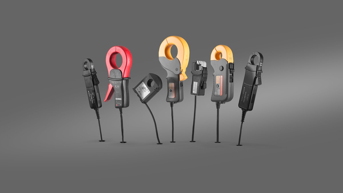
There are many different types of sensors and technologies used to measure current. From the well-known current transformer to the latest DC-CT® flux technology. There is a solution for just about every current measurement challenge today. In this article, we will take a look at each of these technologies. We will compare and contrast their advantages and disadvantages, as well as their costs and suitabilities by application.
What are the major types of current sensors?
Current Transformers
DC-CT® Platise Flux
Fluxgate / Zero Flux
Open-loop Hall Effect
Closed-loop Hall Effect
Fiber-optic currents sensors
Shunt Resistor
Rogowski Coil
Comparison of various current sensor technologies
| Type | Principle | Advantages | Disadvantages | Applications | Cost |
|---|---|---|---|---|---|
| Current Transformer (CT) | The current induced in a secondary winding is proportional to the primary current. | Excellent accuracy, and high reliability. | Limited bandwidth, size, and weight can be substantial. | Power systems, protection, metering. | Moderate to high |
| Platiše Flux (e.g., DC-CT®) | Magnetic field modulates the permeability of a core material. | Very high accuracy, low-temperature drift, low power consumption | Cost may be higher in some applications | Precision, high bandwidth current measurements, power analysis. | Moderate to high |
| Fluxgate | Magnetic field modulates the permeability of a core material. | High accuracy, low hysteresis. | Complex design, higher cost, sensitivity to magnetic fields, high power consumption | Precision current measurements, power analysis. | Moderate to high |
| Open-Loop Hall Effect | A magnetic field induces a voltage in a Hall element without feedback. | Simple design, cost-effective. | Susceptible to external influences, lower accuracy. | General-purpose current sensing. | Moderate |
| Closed-Loop Hall Effect | A magnetic field induces a voltage; feedback adjusts for accuracy. | Higher accuracy, better linearity. | More complex design, higher cost. | Precision applications, motor control. | Moderate to high |
| Fiber Optic | Faraday effect induces a change in light polarization. | Excellent electrical isolation, suitable for high-voltage systems. | Limited bandwidth, may be affected by environmental factors. | High-voltage and EMI-sensitive environments. | High |
| Shunt Resistor | Measures voltage drop across a known resistor in the current path. | Simple and cost-effective. | Power dissipation can affect the circuit's impedance. | Power supplies, battery monitoring. | Low to moderate |
| Rogowski Coil | The voltage induced in a coil is proportional to the rate of change of current. | Flexible and non-intrusive, suitable for irregular conductor shapes. | Integrating signals requires additional processing. | High-frequency AC current measurement, power quality analysis. | Moderate |
Current transformers
What is a current transformer?
The primary function of a current transformer is to divide or “step down” very high AC currents to lower levels for safety and easier measurement. They don’t change the current into something else - they simply divide it. Their stepped-down outputs are sent to ammeters and other instruments for monitoring purposes, as well as to relays and other systems for protection applications in power systems.
How current transformers work
A Current Transformer (CT) operates via the principle of electromagnetic induction. Changing the current in a transformer induces a voltage in another coil by varying the magnetic flux. A current transformer has a single-turn primary winding, also known as a “bar primary.” This primary carries the full current.
The secondary winding (B) has many turns, the output of which is a division of the current. The ratio of primary to secondary windings is what determines the output level that is measured at the secondary’s output (A).


Current Transformers are known for high accuracy and linearity within the measurement range that they are designed to handle. As a result, they are used heavily in power generation and transmission applications. They provide galvanic isolation and are often used in applications involving very high currents.
Current Transformers are available in both solid core and split core form factors. A solid core is a toroidal “donut” shape. This means that the bus bar must be disconnected from power to pass it through the core. In some applications this is not feasible, a split core CT allows the core to be opened.
Inexpensive iron core clamps are another example of current transformers. They work on the same principle, and as a result, can only measure AAC.


Current transformer key points
Current transformers can handle very high currents
Current transformers provide an electrically isolated output
Current transformers handle AC (AAC)
Current transformers provide an output that is a division of the original current
Current transformers are used for safety purposes and easier measurement
Fluxgate current transducers
Fluxgate current transducers use the principle of magnetic flux modulation to measure electrical currents. They have a magnetic core made of a highly permeable material, such as a nickel-iron alloy.
The magnetic core is typically shaped like a toroid. The primary winding is wound around the magnetic core. The current passing through the primary winding induces a magnetic field in the core.


An excitation coil is also wound around the magnetic core, and an alternating current (AC) is applied. The AC generates a magnetic field that periodically saturates and demagnetizes the magnetic core, inducing a modulation within the core. This modulation induces an alternating voltage in the secondary winding. A feedback coil provides feedback to the excitation coil.
A fluxgate sensor’s output is a low-distortion, accurate representation of the primary current. The output signal is typically in the form of a low-voltage AC signal that can be further processed or converted for use in measurement and control systems.
Fluxgate current transducers are capable of high accuracy and are often used in applications where precise current measurements are essential.
DC-CT® current transducers
The DC-CT brand represents a new type of zero-flux AC/DC transducer using Platiše Flux Sensor technology. It offers improved bandwidth, accuracy, stability, and lower energy consumption.


Current-controlled variable reluctance is at the heart of the DC-CT. A kind of “infinity winding” is embedded into a gap-less core that retains all of the good properties of high permeability materials.
The result is a new type of flux sensor named after the inventor - Platiše (Flux Sensor). The DC-CT® brand name is a registered trademark of ISOTEL. Dewesoft builds the sensor under license.


Compared to Hall-effect-based sensors, the DC-CT solution does not create an air gap and retains a very high sensitivity and immunity to external magnetic fields. In addition, it is temperature-independent.
While a typical fluxgate transducer resets and demagnetizes its core repeatedly, the DC-CT has to do this only occasionally and is more energy efficient. DC-CT sensors can measure both AAC and ADC. Models range from 2 A and up to 2000 A, with bandwidth -3dB @ 750 kHz, with target accuracy from 0.1% down to 0.01%. Other potential uses include DC/AC residual current sensors of class B+.

Hall effect current transducers
The Hall effect currents sensors utilize the Hall effect, which generates a voltage perpendicular to the flow of current in a conductor in the presence of a magnetic field.
The Hall effect refers to the generation of a voltage difference, known as the Hall voltage, in an electrical conductor. This voltage is produced perpendicular to the electric current flowing through the conductor and the applied magnetic field, which is also perpendicular to the current. It was discovered by Edwin Hall in 1879.
Hall effect current transducers are contactless, providing galvanic isolation between the current source and their output. They are often used in applications where isolation is important.


Both open-loop and closed-loop Hall effect current transducers are available today. Open-loop Hall effect transducers provide an output voltage or current proportional to the strength of the magnetic field. This output is not actively controlled or compensated. Open-loop transducers can be affected by ambient temperature and aging effects.
Closed-loop Hall effect current transducer
Closed-loop Hall effect current transducers incorporate a feedback mechanism to control the Hall sensor's output actively. This feedback loop adjusts the output in response to changes in the magnetic field, compensating for environmental factors like temperature, and providing more stable and accurate measurements.

 schematic")
Due to their relative complexity, closed-loop sensors can be more expensive than open-loop current sensors. But when higher accuracy and stability are important, closed-loop transducers are a better choice.
Rogowski coil current transducers
Rogowski coils are flexible air-core coils that encircle a current-carrying conductor. They generate a voltage proportional to the rate of change of current. The principle behind Rogowski coils involves the detection of the rate of change of current over time, and they are most effective when measuring rapidly changing or dynamic currents, such as those found in AC circuits. They do not apply to DC applications.


Rogowski coils are physically flexible and lightweight. Their measurement loops are available in a wide variety of circumferences. Their design makes it easy to connect around existing conductors.
Shunt resistor current transducers:
Shunt resistors are connected in series with the load in an electrical circuit. The load is typically the primary circuit, and the shunt resistor creates a parallel path for current flow. Employing Ohm’s law, the current flowing across the shunt produces a voltage drop proportional to the current.
Shunt resistors are designed to have a relatively low resistance to minimize the voltage drop across them. This ensures that the impact on the original circuit is minimal, and the measurement is accurate.


Shunt resistors are suitable for both high and low-current applications and can be used in both AC and DC systems. Shunt resistors are found in ammeters, battery management systems, power supplies, motor control systems, and thousands of other applications.
Fiber optic current transducers
Fiber optic current transducers use the Faraday effect, where the polarization of light passing through a fiber optic loop changes in response to the magnetic field induced by the current. The core of the fiber optic transducer contains a magneto-optic material that is sensitive to changes in the magnetic field.


Fiber optic current transducers are commonly found in high-voltage and high-power applications, like power distribution systems and electrical substations, where electrical isolation and accurate current measurements are critical. They offer advantages in terms of safety, reliability, and performance in environments with high electromagnetic interference.
Conclusion
The choice of a current sensor depends on the specific application requirements. CTs are reliable for high-current AC measurements. Dewesoft’s DC-CT® is suitable for high-end AC and DC measurements. Hall effect sensors offer versatility, and specialized sensors like fiber optics are suitable for high-voltage environments.
Costs vary, with traditional methods like CTs and resistor shunts being more economical compared to high-precision sensors like Flux, fiber optic, and Hall effect sensors.