


Calculating the Pulling Strength of Chains and Tie Rods in a Heritage Building

Preserving Italy's historical heritage is crucial to protecting our cultural identity. The Casa Desanti-Bossi in Novara is an identifying element of Italy’s rich history. Today, reinforcement systems, particularly tensioning rods, guarantee the structural stability of this heritage and ensure modern safety and usability needs. Engineering Controls Srl used Dewesoft to analyze the tie rods' resonance frequencies. They also monitored the structure and support systems. This helps prevent damage and reduces maintenance costs.
Engineering Controls Srl is an Italian structural engineering company formed in 1988. Its operations include civil, geotechnical, and road engineering through laboratory tests and on-site materials investigations. L'azienda ha deciso di monitorare e analizzare la grande villa a Novara, Casa Desanti-Bossi. Questa villa è stata progettata dal famoso architetto Alessandro Antonelli ed è un simbolo dell'architettura neoclassica italiana.
Construction and historical evolution
Alessandro Antonelli (July 14, 1798 – October 18, 1888) is known for his important buildings. These include the Mole Antonelliana in Turin, which is named after him. He also designed the Novara Cathedral and the Basilica of St. Gaudenzio in Novara.
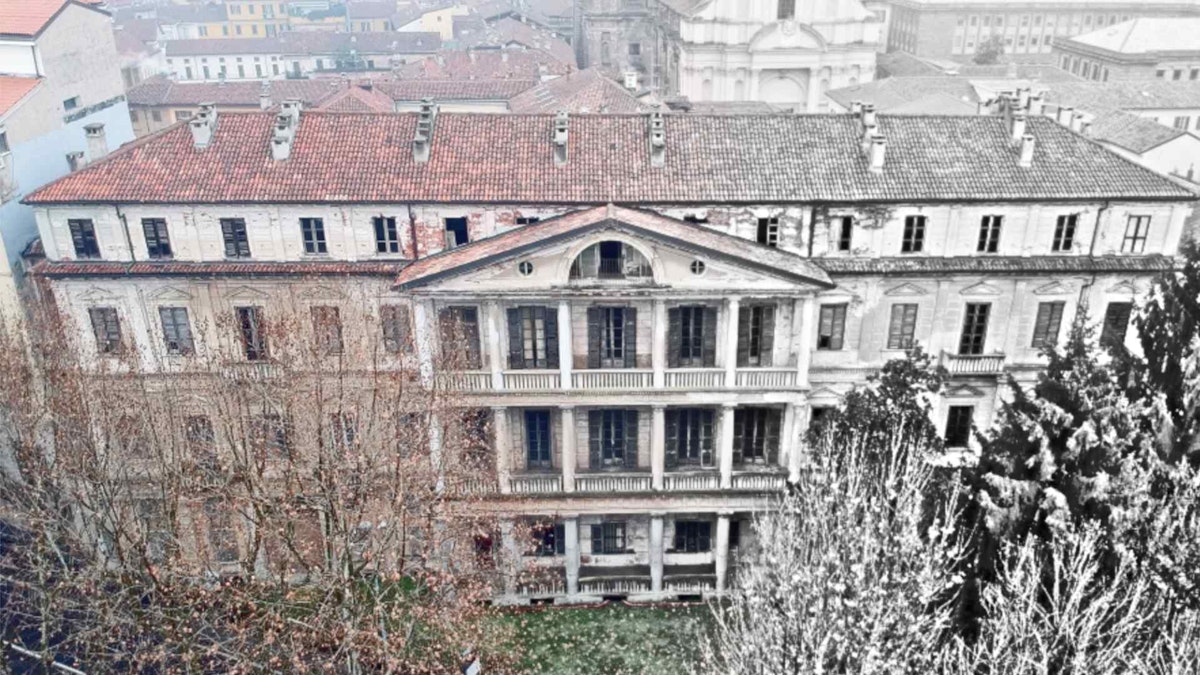
Built between 1857 and 1861, Casa Desanti-Bossi stands out for its balance between monumental forms and decorative details. Antonelli designed the house in Novara as a new type of middle-class home. It reflected the changes in society during the nineteenth century. This period saw economic, social, and cultural shifts as modernity began to take shape.


Initially owned by the Desanti family, Casa Bossi changed owners and functions several times. In 1880, Cavalier Carlo Bossi purchased the building, and his name has remained linked to it. After the last Bossi heir died in 1951, the building was given to a boarding school. The school is called the Civico Istituto Dominioni. Later, in 1990, it was donated to the Municipality of Novara. In 1980, Casa Bossi was placed under monumental constraint, recognizing its historical and artistic importance.
The building represents a perfect example of neoclassicism but also incorporates elements that anticipate romanticism and the transition to a more industrial building production. Antonelli created a work that mixes new living spaces with traditional decorations. Casa Bossi shows the cultural changes of that time.


Structural problems and deterioration
Over the years, Casa Bossi has progressively deteriorated. Non-original interventions, such as the adhesion of other buildings to the façades, have hidden some decorative details. At the same time, neglect has left many areas of the building in decay. Only in recent decades have the community and authorities recognized the need for structural and conservative interventions.
In 2010, the local community and the FAI promoted projects to redevelop the building. FAI is a non-profit foundation established in 1975 to protect and enhance Italy's historical, artistic, and landscape heritage. Among its most significant projects is “Casa Bossi – Centro Culturale Urbano e Sistema Antonelliano,” aimed at transforming the building into a cultural center. This project involved structural consolidation interventions and the introduction of technologies for monitoring and managing spaces, respecting the original style.
For further information, visit the FAI website.
Consolidation of arches and vaults
The inside has masonry arches and vaults. These are common in old buildings to help support the upper floors. However, over time, these elements can suffer from structural deterioration. This process, often accelerated by water infiltration, vibrations, earthquakes, or excessive loads, leads to cracks, deformations, and partial failures. Internal stresses can compromise general stability, especially when the piers or buttresses do not adequately contrast the horizontal thrusts.


Consolidation with tie rods
A widely used technique to mitigate stability problems is consolidation with tie rods. Engineers install these metal parts, or sometimes advanced materials, to hold back side forces. This helps spread the loads and stabilize the structure. They can apply tie rods in different ways:
Inside the arch or vault: They are hidden inside the masonry, preserving the work's aesthetics.
On the extrados of the vaults: Integrated with collaborating caps in concrete or composite materials.
Combined with new structures: New structures connect arches to frames or upper slabs. This change makes the vaults act like "hanging" elements. These elements help reduce the thrust on the piers.
These interventions often use new materials like fiber-reinforced mortars or epoxy resins. They improve load-bearing capacity without changing the historical and architectural value of the structures.
Although these elements reinforce the structure, they are also subject to deterioration agents that affect the tensile stress. The deterioration can concern the constituent material or the constraint point of the tie rod itself. For this reason, Engineering Controls Srl monitored the tension state of the tie rods. It could do such monitoring in two ways:
1. Static method
This method is based on the static equilibrium of the chain and considers:
Self-weight of the chain: Force on the linear mass due to gravity.
Chain geometry: Length, deflection (curvature), and type of constraint (support or interlocking).
External loads: Forces applied to the structure (for example, wind or distributed loads).
Engineers calculate tension using formulas from the mechanics of rigid bodies. They look at the relationship between weight, length, and curvature in a catenary chain. Tension formula for catenary chains:
Where:
T is the maximum tension (tension),
q is the distributed load (e.g., weight per unit length),
L is the length of the chain,
f is the deflection of the chain.
2. Dynamic method (modal analysis)
This method uses the dynamic response of the chain to estimate tension. It is useful when forces, e.g., wind or traffic, subject the chain to vibrations. The steps include:
Measuring natural frequencies: Sensors like accelerometers or geophones can identify the oscillation frequencies.
Comparison with theoretical models: The equations for a vibrating system help us understand how to calculate tension. This tension is necessary for the chain to vibrate at specific frequencies.
Relationship between pull and frequency:
Where:
TTT is the pull,
mmm is the linear mass of the chain,
LLL is the length of the chain,
fff is the natural frequency of a given mode.
Tie rod analysis setup - Desanti-Bossi house


Engineering Controls Srl conducted dynamic tests to study the tension of the tie rods in the Desanti-Bossi house.
The engineers configured the system as follows:
Acquisition software: DewesoftX
Data Acquisition System (DAQ): DEWE-43A
Uniaxial Accelerometer: MMF KS48C
Modal analysis software: Dewesoft Artemis OMA
This analysis aimed to provide the tension values by varying the constraint hypotheses on the tie rod. The engineers got the tension values from the resonance frequencies. They used an OMA analysis of the tie rod's vibrations caused by environmental noise.


Pull strength calculation procedures
The chain pull values were obtained by following well-defined steps in the tie rod analysis phase:


1. Identification of the chain parameters
The geometric and mechanical characteristics of the steel chain are:
Ø (diameter): 2.40 cm
A (section area): 4.52E-04 m²
Specific weight: 7830 daN/m³
Elastic modulus (E): 1.96E+10 daN/m²
These values define the resistance and elastic behavior of the material in the event of a load.
2. OMA analysis of the tie rod
Once Engineering Controls Srl has acquired the accelerometer values, the engineers identify the resonance frequencies at which the chain naturally oscillates. Although the analysis aimed to determine the resonance frequencies, a simple FFT would not have been sufficient to define the frequencies in question. Each oscillating element of the structure directly connected to the tie rod represents a source of spectral noise in the identification of the resonance frequencies of the tie rod. For this reason, the modal analysis with the study of the modal shapes of the tie rod was necessary to exclude any disturbance frequencies present in the spectrum.

Colored indicators represent the stable (yellow) and unstable (red) modes.
Frequencies on the X-axis show the resonance points of the chain, highlighted by the vertical lines.
3. Calculation of the tension in the chain
Engineering Controls Srl presented the calculation of the tension (T) for two constraint hypotheses:
Support-support: supporting the chain at both ends.
Interlocking-interlocking: rigidly blocking the chain at the ends.
Each constraint mode creates different tension values (measured in daN). These values show the internal forces needed to keep the chain balanced.
Analytical formulas can calculate the tension in a chain starting from its natural vibration frequencies that consider specific simplifying hypotheses. It is assumed that:
The chain has uniform geometric characteristics along its entire length.
The tensional stiffness of the chain is negligible.
The end constraints are rigid (not deformable).
The engineers obtained tension T from the relationship with the system's natural vibration frequencies. In mode n, the natural frequency fn is based on several factors. These factors are important. They include:
Chain length (L)
Elastic modulus (E)
Linear weight (Pl)
Gravitational acceleration (g)
Constraint coefficient (kn)
Where:
n is the vibration mode considered.
J is the moment of inertia of the chain section.


Conclusions
Casa Desanti-Bossi is still a place of great cultural and symbolic interest, despite ongoing challenges with degradation. The Novara community is working to restore the building to its former beauty. They combine new technology with respect for history.
It is very important to keep an eye on the building parts and support systems. This helps protect the heritage from slow and natural damage.
The analyses carried out on the tie rods are fundamental to this monitoring process. They require instruments and procedures that do not damage the structure during the analysis phase.
The reports from Engineering Controls Srl show the work done to protect the structure. Specialized engineering firms will interpret the symptoms correctly. This type of analysis is, therefore, essential for:
Evaluating the safety of the structure.
Identifying possible critical issues (for example, excessive stress or instability).
Planning maintenance or reinforcement interventions.
Thanks to Engineering Controls Srl and the engineers who performed the analyses for sharing the material shown in this article. In particular, thanks to:
Geometrist Davide Gondolo
Engineer Alessandro Gaiotti
Architect Diego Dutto