


Static Fire Test of a Student-Built Rocket Engine
Inas Haddouch
Inholland University, AQUILO Rocket Team
August 13, 2025
The AQUILO Rocket Team at Inholland University conducted a static fire test of their PB-51C solid rocket motor. This test gave critical insights into the motor’s thermal and thrust behavior, revealing both expected results and anomalies. Thermocouple data confirmed safe temperature thresholds, while load cell readings showed unexpected thrust spikes. Using Dewesoft’s high-performance data acquisition systems, these findings are shaping the next steps in motor development.
For the past year, the AQUILO Rocket Team has been designing, building, and will soon be testing the next-generation rocket, AQUILO IX. With this, we aim to participate in EuRoC 2026, a European competition for student-designed and built rockets.
The AQUILO Rocket Team
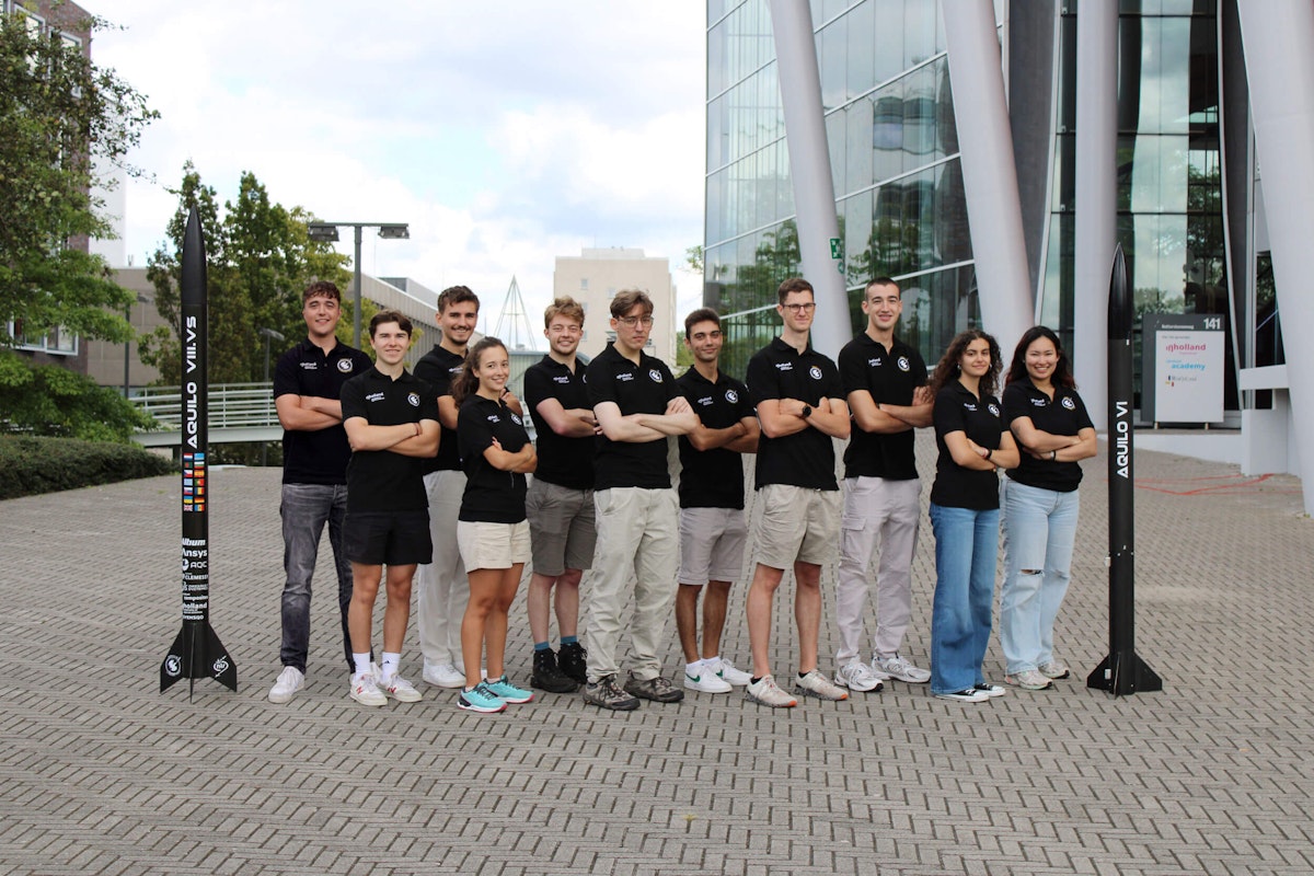
AQUILO Rocket Team is a student team from Inholland University of Applied Sciences in Delft. Each year, students from more than 20 different countries and backgrounds come together to push boundaries and build a new rocket using innovative technologies and ambitious goals, with a single purpose in mind: to launch the rocket by the end of the year.
The carbon fiber aeroshell, flight computers, recovery mechanisms, and propulsion systems are all manufactured in-house, which is what distinguishes the AQUILO Rocket Team. This production not only helps us develop teamwork and communication skills, but also gives us hands-on experience as we collaborate with different departments within the team and various sponsors to build a functional rocket.
The AQUILO IX rocket
The AQUILO IX can carry a payload with dimensions of 100 mm x 100 mm x 100 mm. These dimensions yield a minimum diameter of 141.42 mm required to accommodate the payload in a circular cross-section. As such, the diameter of the aeroshell would need to be at least 151 mm to accommodate the payload.


Additionally, the AQUILO Rocket team aims to participate in the solid rocket category, specifically in the 3,000m category. This competition requires the rocket to achieve as close to 3,000 m of apogee as possible using a solid motor.
We haven’t considered such a payload and altitude requirement before. The highest altitude we have attained is around 2,605 m. With a total rocket mass of approximately 40 kg, the propulsion department has a challenging mission to create a robust motor.
Aeronautical engineering
That’s where the ballistics come into play. I am the head of the propulsion department for the 2024-2025 academic year. I am a second-year Bachelor’s student in aeronautical engineering at Inholland University of Applied Sciences. Before joining the AQUILO Rocket Team, I had no intention of working in the aerospace or aeronautical field.
Focused on aerodynamics, propulsion, structures, materials, and avionics, aeronautical engineering combines many aspects of classical electrical, electronic, and mechanical engineering.
Throughout my childhood, I was captivated by the fields of mathematics and physics. Knowing that I desired to pursue engineering, I believed that aeronautical engineering could be the right fit for me. After hearing about AQUILO Rocket Team, I decided to apply to join the team. Little did I know a bright future awaited me.
With a clear goal and a strong team, AQUILO has become an essential part of my life. Being both ambitious and determined, I constantly pushed myself and my department to new limits.
Within a short time, we secured a valuable sponsorship with Microlan, a leading manufacturer of high-precision products.
On March 21st, 2025, we successfully relaunched AQUILO VIII.Vs a smooth launch, which hadn’t happened in a while. We also designed a new bulky rocket motor for AQUILO IX, which we plan to manufacture and test in April and May 2025.
As the saying goes, “Teamwork makes the dream work.” Despite facing difficult moments, including necessary design changes and tight deadlines, we successfully overcame these challenges and made significant progress.


Propulsion - rocket motors
As the propulsion department of the AQUILO Rocket Team aims to test the AQUILO IX motor in May 2025, similarly to the previous motors, this study will focus on testing the PB-51C (Microman), for which we will reproduce the setup for the new motor.
First of all, it is crucial to understand what type of rocket motor AQUILO produces. In rocketry, there are three types of rocket engines:
Solid, used in fireworks. Fuel and oxidizer are mixed together into a solid material (called propellant) and packed into the rocket.
Hybrid, used in some boosters.Uses solid fuel and a liquid or gas oxidizer (like nitrous oxide)
Liquid, usually used for space shuttles. Fuel and oxidizer are stored separately as liquids, e.g., liquid oxygen, and pumped into a combustion chamber.
These categories express the physical state of the propellant. AQUILO Rocket Team manufactures solid rocket motors mainly because they are cheaper and easier to produce.
Of course, we control the production of such explosives. As such, within the team, some students undergo a police investigation to obtain a professional license that allows them to manufacture the propellant.
These solid rocket motors are composed of four main parts - see Figure 3:
Casing
A tube that embodies the propellant, the forward closure, and the nozzle.
Nozzle
The exhaust gases resulting from the burning of the grains evacuate through an outlet section (the nozzle) that is similar to a Venturi tunnel with a diverging-converging channel. The gases are accelerated, and the pressure increases, creating thrust. The nozzle is at the end of the casing.
Grains
They are different sections that constitute the propellant. Once burned, they create exhaust gases.
Forward Closure
Located at the top end of the casing, it serves as an interface connection between the motor and the rest of the rocket. It also helps restrain the built-up pressure within the casing to avoid any structural damage to other parts of the rocket.

 the casing, 2) the nozzle, 3) the grains, and 4) the forward closure.")
The AQUILO team designed PB-51B to serve as the booster for a two-stage rocket. However, the rocket exploded due to motor overpressurization on May 12, 2023, and thus, we had to find a new replacement, which we decided to be the PB-51C.
The PB-51C, also known as Microman, is a motor design based on the PB-51B, featuring increased thrust and utilizing radial bolts instead of circlips for retention. For safety protocols and confidentiality reasons, we do not reveal the specific dimensions of the motor.
After designing and manufacturing the Microman, the final validation before a launch is a static fire test. A static fire test is a test in which the motor is on a test stand that is securely attached to the ground. We then ignite the motor and record the test data. To record the data, AQUILO Rocket Team uses a Dewesoft data acquisition system along with the Sirius box.
Test setup
When testing a solid rocket motor, three data types are essential to acquire: temperature, pressure, and thrust. For this test, we did not use a pressure transducer due to budget constraints. As such, the setup consisted of four thermocouples and two load cells.
Thermocouples
The thermocouples employed are of type K, which are capable of withstanding temperatures of up to 250°C. We do not apply a specific simulation to predict the temperature range in the different sections of the motor. However, we position the thermocouples strategically at various locations around the casing where the likelihood of encountering elevated temperatures is highest.
Thermocouples ensure that the temperature of the aluminum tube does not exceed a certain threshold during the propellant burn, which could lead to structural damage during flight. They are installed by first applying thermal paste to the desired location, then inserting the thermocouple end into the paste, and finally securing it in place with aluminum tape. Figure 4 shows the thermocouples in four distinct locations:
Thermocouple 1
Just below the forward closure, stagnation of the gases, so a potential hot spot
Thermocouple 2
In the middle of a grain, it is likely to experience the least heating
Thermocouple 3
In between two grains, another potential hot spot
Thermocouple 4
Just above the nozzle’s convergent section, likely to experience the most heating


Load cells
The load cells are of type S and have a range of 200 kg to 1000 kg, meaning they can measure loads between 1962 N and 9810 N of ultimate load (tension or compression). The two load cells are mounted in series and should provide approximately the same reading during a test, which we can use to see and verify the differences between the load cells.
This difference is usually negligible. From the reading provided by the load cells, the thrust of the motor can be concluded and compared with the expected performance. Using OpenMotor simulation software, the predicted thrust curve is even, which means that the thrust profile remains relatively constant throughout the burn (see Figure 10).
The load cells connect via an M12 threaded hole. This hole is located on one side and is associated with an M12 bolt that passes through the thrust plate in the test stand. The other side connects to an M12 to M6 insert. This insert is then attached to the motor via the M6 threaded rod of the forward closure, as shown in Figure 5.
For further details regarding the sensors employed, please check References 3 and 4.


Data acquisition
Dewesoft SIRIUS
High-end signal conditioning amplifier with high dynamic range (160 dB), galvanic isolation, etc.Dewesoft SBOX
Powerful Data Processing Computer and SSD Data LoggerDewesoftX software
Data acquisition and digital signal processing software
Figure 7 shows the thermocouples and load cells connected to the SIRIUS data acquisition system using different channels. A corresponding test setup is configured within the DewesoftX software to facilitate and organize data collection, as shown in Figure 6.


Test results
Once the ignitors are in place and the countdown to ignition is complete, we ignite the PB-51C motor, and data acquisition begins.


Thermocouples
Temperature readings from the thermocouples vary depending on their positions along the motor casing. As expected, the highest temperature during burning was observed by Thermocouple 4, located near the nozzle convergent section, reaching a peak of 156.284 °C.
On the other hand, the lowest temperature was recorded by Thermocouple 3, positioned between two grains, with a reading of 31.229°C. We consider this result to be a positive indication, suggesting that no significant hot gas flow affects the space between two grains.
As a result, the risk of erosive burning in this area is minimal. Erosive burning is an undesired modification/acceleration of the burning rate of the propellant due to the fast-moving gases. This phenomenon is unfavorable when aiming to maintain a uniform thrust profile and achieve high-altitude performance targets, such as reaching an altitude of 3,000 meters.
The thermocouple placed just below the forward closure indicates the surrounding temperature. According to thermocouple 1, the maximum temperature reached is 91.167 °C. Given that this peak occurs only for a brief duration (on the order of milliseconds) and remains well below the melting point of aluminum (approximately 660 °C), we can conclude that the forward closure is not at risk of significant thermal damage.
Consequently, we expect no structural compromise at the interface between the forward closure and the rocket’s bulkhead during flight. This conclusion confirms that heat buildup will not cause the motor to disconnect from the rocket under operational conditions (see Figure 9).


Load cells
Contrary to the thermocouples, the data acquired by the load cells does not align with what we initially predicted. Both load cells exhibit unevenness in the load-bearing casing during the burning period, resulting in an uneven thrust profile. Since both load cells yield similar readings with a negligible difference, this suggests that the cause of the problem is not sensor malfunction but rather a potential manufacturing issue with the propellant.
The maximum thrust reached is an average of 5,488.075 N, and a total impulse (integrated thrust) of 3,781.93 Ns. These values compare to the expected ones of 2,300 N and 3,728.74 Ns. These numbers represent a significant difference of approximately three times more thrust created – see Figure 11.


After reviewing the slow-motion footage of the motor burning (see Figure 12), we observed that a solid piece exited the motor rapidly during the firing process. This occurrence correlates with a sudden and violent increase in thrust.
The suspected source of this anomaly is the ignitor holder. The ignitor holder is a circular piece of wood that is placed just below the forward closure and on the top grain. This piece helps to keep the ignitor in position.


The potentially damaged ignitor holder may have caused a piece of wood to burn with the propellant. The event led to an increase in internal pressure, which we attribute to the sudden spike and distortion of thrust evenness, with no significant difference in total impulse change.
Although this theory remains an assumption, we did not account for the sudden increase in thrust during the simulations, which led to the structural failure of some parts of the motor – see Figures 13 and 14.


Conclusion
As a result of the static fire test conducted on the Microman on May 31, 2024, we can draw one major conclusion: Use a thicker ignitor holder or cover it with aluminum tape to prevent structural failure of the part when designing motors with a thrust greater than 2,000 N.
Moving forward, my department and I will take the approach of protecting the ignitor holder with an ablative material such as silicone-based coatings. This approach will be undertaken and tested in the static fire test scheduled for the AQUILO IX motor on May 23, 2025.
In terms of the DEWESoft Data Acquisition Software and the SIRIUS SBOX, after the thrust limit has been exceeded on the 200 kg load cell (Ploadcell = 1,962 N < T = 5,488.075 N), potentially risking sensor failure.
As a preventive measure, on April 7, 2025, we calibrated the load cell, connected it to the SBOX, and confirmed its functionality. Thus, for the upcoming static fire test, the setup is fully operational and ready to be used, as we hope that no unforeseen events will occur.
Lastly, AQUILO Rocket Team and I would like to extend our sincerest thanks to Dewesoft for sponsoring us through the granting of access to your advanced and user-friendly DAQ systems. Your guidance and assistance have truly helped us push our boundaries, improve our propulsion systems, and predict and understand the performance of our motors during a launch.
References
Dewesoft Downloads. (2025, April 6). Data Acquisition | Test and Measurement Solutions.
SIRIUS® | Powerful USB and EtherCAT DAQ System | Dewesoft. (2025, April 6). Data Acquisition | Test and Measurement Solutions.
RS PRO Type K Thermocouple 1m length, 2mm diameter → +250°C | RS. (n.d.).
S-Type load cell S20S | BOSCHE - Precise measurement for industrial applications. (n.d.). BOSCHE Wägetechnik.