


Pulse Width Modulation Control and Monitoring on Test Bench for Underwater Thrusters
Team PoliTOcean
Polytechnic University of Turin
August 19, 2025
Pulse Width Modulation (PWM) is a digital technique used to control the average value of an analog signal by varying the width of pulses while keeping the frequency constant. PWM is useful for controlling the average power or amplitude delivered by an electrical signal. PWM can control a wide range of devices, from small LEDs to large motors, making it a versatile solution for various electronic systems.
Many power supplies utilize pulse-width modulation (PWM) to regulate output voltage and current. By controlling the duty cycle of the signal, PWM helps maintain stable voltage levels in sensitive electronic devices, such as computers and communication equipment.
The PoliTOcean team
The Team PoliTOcean is a student team from the Polytechnic University of Turin, specializing in underwater robotics, and participates in the MATE ROV Competition. This international contest is held annually in the United States, bringing together teams from around the world. PoliTOcean has proudly represented the university since 2017. The competition features various Remotely Operated Vehicle (ROV) prototypes, which are challenged and evaluated in complex underwater tasks.


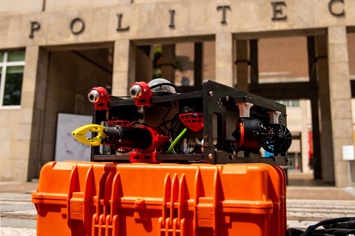
With over 75 active team members, challenges are never in short supply, especially when it comes to our latest and most advanced ROV, EVA - see Figure 1.
We design and prototype all components, from mechanical to electronic, in-house. Eurocircuits manufactures our Printed Circuit Boards (PCBs), while we utilize a Prusa printer for 3D printing, enabling us to fabricate custom parts using filaments supplied by Filoalfa. The chassis is in High-Density Polyethylene (HDPE), a thermoplastic polymer derived from petroleum, and we cut it using a CNC machine owned by our mentor, Claudio Sansoè.
Full team members working on this project:
Giovanni Pellegrino, Electronic and Data Science Engineer
Student Gino Marco Fachechi, Firmware
Student Mahdi Nassereddine, Mechanics
Student Pietro Canta, Electronic engineer, Electronics,
Student Fabio Casini, Electronics, and Michele Carenini, Software
The EVA prototype
The EVA prototype has eight thrusters, ensuring precise and stable maneuverability in underwater environments. We base its navigation system on an IMU coupled with a Kalman filter, supported by a barometric sensor for depth calculation and five cameras providing real-time visual feedback. We have constructed the vehicle’s structure using HDPE and aluminum alloys, materials chosen for their strength and pressure resistance, enabling EVA to operate at depths of up to 100 meters.


During the design and prototyping phases of the new ROV, we do not reinvent the wheel each time; instead, we reuse functional, optimized, and thoroughly tested components from previous models. In the specific case of EVA, we reused the power from AIDA – see Figure 3, the ROV deployed during the 2020 MATE ROV Competition.


However, although this system had not exhibited any issues with the previous ROV, it appears to be inadequate for EVA, particularly during more complex maneuvers. The system has proven unreliable to the point of causing shutdowns and preventing immediate reconnection. This failing raises critical questions: is the issue rooted in an inappropriate component selection, a poorly managed interface with other actuators, or a flaw in the design of our custom-built part?
To test EVA’s propulsion system, we required a test bench capable of accommodating up to eight thrusters, each with individual pulse-width modulation (PWM) control, to perform acceleration and constant-power tests while assessing the power board's efficiency.
The tests were conducted in PoliTOcean’s pool, as shown in Figure 4.


The challenge
In essence, PWM generates a digital signal that represents a varying analog level. This representation is achieved by switching a signal on and off rapidly, with the "on" time (or pulse width) being a function of the desired analog value.
However, for us, a significant challenge was the lack of equipment capable of accurately acquiring data across multiple voltage levels (5V, 12V, 48V). Thanks to the SIRIUS-HD-16xLV by Dewesoft and the DewesoftX software, we were able to visualize waveforms in real time and record both voltage and current data throughout the measurement campaign.


The two DC/DC converters connected in parallel on top of AIDA's power board (see Figure 7) supply a total power of 1200 W, with 600 W from each converter. Our eight thrusters draw a maximum of 200 W each. The full power is not needed, as the competition includes seabed maintenance tasks that require greater precision; therefore, we limit the power to 50% of its maximum capacity.
Therefore:
Even if:
The anomalies observed on EVA (sudden shutdowns, activation of converter protection) do not allow us to rule out a power delivery issue a priori. In fact, with Dewesoft equipment, we plan to analyze the waveforms both in steady-state conditions and during transients.


The Solution
We developed a test bench comprising both mechanical and electronic components (Figure 7).
For the mechanical section, we mounted eight T200 thrusters from Blue Robotics on an aluminum support bar. This setup enables the simultaneous submersion of all thrusters in water, allowing for experimentation with different operational configurations – see Figure 5.
On the electronic side, the Team employed the same boards used for motor control in the ROV. Specifically, the Power board includes two DC/DC converters that step down the 48V input from the power supply into two 12V outputs and one 5V output.
The Opto board features a set of opto-isolated outputs and a socket for an STMicroelectronics Nucleo board, which hosts a microcontroller programmed to control the eight thrusters via pulse-width modulation (PWM) signals. A Blue Robotics driver handles Motor actuation, specifically the Electronic Speed Controller (ESC). They receive 12V and PWM signals to drive the motors via their three-phase outputs.
We used the following equipment:
SIRIUS-HD-16xLV is a multi-channel, high-precision, real-time data acquisition module produced by Dewesoft.
DS-CLAMP 150DC, a current clamp produced and provided by Dewesoft. It allows for the measurement of direct currents up to 150 A.
Power board, developed in-house by the PoliTOcean team
Nucleo board, for PWM signal generation
18-meter cable for ROV power supply and control

 power supply connected with the power board through an Anderson-Powerpole connector.")

Overview of subsystem connections
The power supply used is the Mean Well RSP-2000-48 (220V AC, 48V DC). Figure 9 shows the connection between the power supply and the Power board, established via EVA ROV's 18-meter umbilical cable. The power supply outputs a two-pole cable carrying 48V, which is connected to the umbilical cable using an Anderson-Powerpole (blue) connector. At the opposite end, we use an XT60 connector (yellow) to interface with the Power board.
Figure 9 shows the connections of the cables used for voltage measurements with the SIRIUS HD 16xLV (blue-grey cables).


Figure 10 shows the AIDA power board developed by the team, featuring two DC/DC converters. We designed this board to receive a 48V input and generate two 12V outputs (used to power the thrusters) and one 5V output (for the ST Nucleo board). XT60 connectors (yellow) are used for the 12V lines, as they are well-suited for high-current applications.
Also visible are the voltage monitoring cables (red and grey), which measure the supply voltage on the two 12V motor power lines as well as the 5V line powering the Nucleo board. The 5V supply is tapped directly from the PCB using two wires soldered onto the board (blue and grey cables).
 to the 12V power lines from the Power board. We have split the ESCs into two groups of four for better cable management and current distribution.")
Figure 11 shows the terminal blocks used to connect the cables carrying the 12V power supply from the Power board to two groups, each consisting of four ESCs.
“We decided to split them into two groups,” explains the electronics responsible, Fabio Casini. “Not only to simplify the arrangement of the cables, but also because the Power board features two 12V output channels.” He emphasizes the importance of this choice: “It allows us to monitor the voltage on each channel independently and to distribute the current load more efficiently. Each group of terminal blocks carries +12V on one side and the corresponding GND on the other.”


Figure 12 shows the Nucleo board, in the lower central part of the picture, mounted onto a custom board developed by the PoliTOcean team, referred to as the Opto board. This board integrates several opto-isolated outputs and includes a dedicated socket for the Nucleo board. Eight of the opto-isolated outputs connect directly to the signal cables that carry the PWM signals to the ESCs, enabling control of the thrusters.
For this configuration, we used B2C (Board-to-Cable) connectors, as the same Opto board is also employed in the central ROV system, ensuring compatibility and modularity.
The software setup
We developed the software setup explicitly for this testing event.
“With the help of a GUI, managing the test signals became a fast and easy task,” says firmware responsible, Gino Marco Fachechi, who designed the PWM generator interface. “This GUI allowed us to describe the PWM trend of each motor by entering points on a graph to create the profile for each thruster” – see Figure 13.
By pressing a button, the eight PWM signals are generated and sent to the motors, following the trend of the respective graph.
The software also allows importing test profiles if they are correctly formatted, and we used this feature to create all the tests in advance based on the suggestions and requests provided by Dewesoft.
The graphs prepared in this manner were then imported into the GUI at the time of the respective test, minimizing the time between tests and reducing the likelihood of errors in creating the control profiles.
The GUI and the Nucleo, mounted on the motor board, communicate using a protocol developed by the Team, which transfers specific control and debugging messages between the EVA boards.


The result
The results obtained from the measurement campaign confirmed that the PCB design is correct and performs as desired, meeting the specified requirements.
The limitation identified is due to the DC/DC converter. When the motor demands a current beyond the delivery threshold, the voltage drops sharply to a critical level, causing the component to enter protection mode and shut down.
This behavior is observable in Figures 14 and 15.


We can address this behavior issue in two ways: either by adding a DC/DC converter to distribute the load more effectively, or by performing further measurements to determine more suitable protection thresholds and lower the intervention level, as the component is programmable.


The success factors
The use of Dewesoft instrumentation was crucial to the success of our test campaign. Without the SIRIUS-HD-16xLV system and DewesoftX software, we would not have been able to acquire multiple high-resolution analog signals in real time with precise channel synchronization. This setup allowed us to identify the moments when the DC/DC converter entered protection mode, highlighting phenomena such as voltage drops under load.
Being able to visualize waveforms in real time and analyze them immediately after each test made all the difference: it allowed us to understand where to intervene quickly and gave our work a level of precision we previously lacked.
In fact, without Dewesoft, we would have had to rely on less integrated tools, such as multimeters or low-channel-count oscilloscopes, risking the loss of critical transients or having to repeat tests multiple times to obtain comparable data. Additionally, the ability to log and analyze data offline enabled the accurate diagnosis of issues, thereby accelerating the iteration process for the power board design.
The Dewesoft support, defining test profiles and selecting the proper instrumentation, has proved to be a key added value, reducing setup times and improving the overall quality of the experiment.
The perspectives
The measurements carried out marked a fundamental starting point for the development of PoliTOcean power electronics systems.
We plan to collaborate with Dewesoft in the future to conduct another testing campaign, thereby building an extensive dataset. We will use this dataset to train a neural network capable of predicting the electrical and thermal behavior of the thrusters based on control profiles (PWM), supply voltage, and operating conditions.
The idea is to develop a Multilayer Perceptron (MLP) or Long Short-Term Memory (LSTM) neural network to accurately model the energy consumption and dynamic response of the motors in real-world scenarios. Such a model would enable simulation of propulsion system efficiency and reliability during the design phase, without the need for physical testing—thereby optimizing both component selection and control strategies.

