


Load Circuit Breaker Identification in a Power Distribution Cabinet
Aljaž Kontestabile
Faculty of Electrical Engineering, University of Ljubljana
August 18, 2025
Identifying the correct circuit breaker in large or poorly labeled fuse cabinets—without shutting off power—is a major challenge, particularly in critical environments. This project introduces a compact, pulse-based method that uses flux-gate magnetic field sensing and a Dewesoft SIRIUS data acquisition system. Testing shows the approach is promising for accurately locating live breakers in real-world conditions without interrupting the power supply.
A common issue in buildings is that many circuit breakers, fuses, wires, and outlets are not properly marked. This deficiency primarily affects commercial and larger residential buildings, particularly those in older structures.
The poor marking of circuit breakers in many buildings creates a significant problem for technicians. In numerous cases, it’s not just impractical but also dangerous to cut power to the circuits. Especially those powering critical devices such as servers, medical equipment, measuring devices, and pumps.
While there are a few devices on the market that claim to identify a circuit breaker while it is under power, the reliability of these devices is often in question. Most of them work by injecting a high-frequency signal. In contrast, this project provides a reliable method for circuit breaker identification, instilling confidence in its effectiveness.
I am currently interning as an Engineer at Grid Instruments, a Slovenian company specializing in low-voltage network modeling, analysis, and load imbalance mitigation. Its product portfolio consists of end-to-end solutions and products to analyze, evaluate, and mitigate load imbalance in low-voltage distribution grids, thereby releasing capacity and voltage headroom.
Its handheld instrument, Gridphase, is used as a stand-alone solution for phase identification in the field, helping with manual load reconnections, mapping, and diagnostics. The company also provides a software solution for network analysis and asymmetry evaluation, Gridscope.
When speaking with clients, the company identified an expressed need for a reliable method to identify circuit breakers without turning off the power, and I began to consider how to address this need. If my concept proves successful, we could integrate it into one of our future products.
The design concept
I had the idea to test a few alternative methods of circuit breaker identification, starting with loading the circuit and using a precise flux-gate magnetic field sensor to scan the fuse cabinet and determine the location of the circuit breaker.
Firstly, I created a system using a TRIAC (Triode for Alternating Current). This bi-directional thyristor is a semiconductor used to regulate alternating current loads. I tested the system and proved that it worked well.
However, the system was extensive, generated a lot of heat, and due to pulses being either half or whole periods long, it was also prolonged. Therefore, a change was made to a pulsed system using an SSR (Solid-State Relay) and a MOSFET (Metal-Oxide-Semiconductor Field-Effect Transistor) in the hope of making it smaller and faster.
This system works similarly, but an additional source of voltage is required to switch the MOSFETs on each cycle. This switching allows the current to pass through the integrated diode during a positive wave. At the same time, I put the other into a conducting state by applying a voltage greater than its threshold voltage to the gate pin; on the negative wave, the situation is reversed.


Measurement equipment setup
The primary DAQ device used for testing was the Sirius HS. To measure load, a flux-gate magnetic field sensor board, DRV425EVM from Analog Devices, was employed. The Sirius HS can power it and features a 0-5 V signal output, as well as the ability to detect magnetic flux densities equal to microteslas (10−6 Tesla).
For the measurement, I first required a controllable load, so I designed a control circuit for this purpose. I assembled a custom zero-cross detector circuit to detect the zero-crossing of the sine wave in the mains voltage supply, allowing a switching circuit to trigger with correct timing. This functionality is necessary to initiate the switching and maintain a constant frequency. The circuit triggers a ~1 ms long symmetrical pulse around the zero-volt transition.
Next assembled was a MOSFET-based SSR. I chose this SSR over a classical TRIAC-based SSR as the TRIAC cannot be closed once opened until the next zero-crossing. The MOSFET-based SSR can switch the load multiple times during one sine period, which also allows it to be potentially programmed, if used in various instances. Additionally, it has lower resistance.
Both circuits connect to the microcontroller unit (MCU), STM32, via optocouplers for isolation. When the MCU detects a zero-crossing, a few MOSFET SSR pulses are triggered, loading the circuit with an additional current (approximately 1 A at the trigger voltage). A flux-gate sensor displays this increased current as an increased magnetic field density.
Measurement devices and components:
Dewesoft SIRIUS modular: A high-speed data acquisition (DAQ) device for precise signal capture and analysis.
Analog Devices DRV425EVM: A flux-gate magnetic field sensor board to detect magnetic field density changes around circuit breakers.
SSR (Solid State Relay): MOSFET-based - Custom-built SSR for pulsing the load circuit.
Custom Zero-Cross Detection Circuit: Detects the sine wave zero-crossings of the AC mains for synchronized load pulsing.
STM32 Microcontroller (MCU): Controls pulse timing and switching logic, interfaces with SSR and zero-cross detector.
Optocouplers: Provide isolation between the MCU and the high-voltage circuits.
Resistive Load: 2 × 330 Ohm, 50W resistors in parallel (total: 165 Ohm), to induce a detectable current pulse.


Data analysis
Firstly, I performed a check of all circuits to ensure that both zero-cross and MOSFET SSRs function correctly. The reading in Figure 3 shows that the zero-cross correctly detects the event at approximately half of the pulse (this device, I don’t need higher accuracy).


Triggering of the MOSFET SSR also works well. Initially, I tested longer pulses, but they overheated the resistors, so I selected shorter pulses. I activated pulses on every second positive or negative wave for easier recognition. Figure 4 displays the voltage across the resistors.


I could also observe Pulses with a flux-gate sensor attached to the line that went to the resistors. The sensor also detected the magnetic field density of nearby circuits, but I observed a change in the waveform, as shown in Figure 5.


My first observation is that the change is not consistent with the pulses. There are three voltage pulses, but only one spike in the magnetic field density. One approach to consider is to mirror pulses on the other side of the voltage peak, resulting in two spikes in the magnetic field density, which facilitates easier detection.
Real-world tests
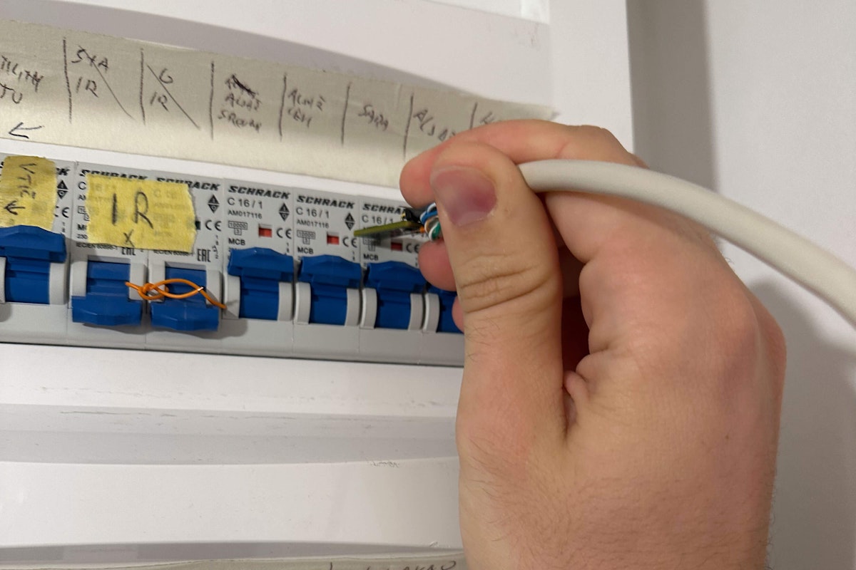
I conducted the measurements on the fuse cabinet in a residential home. A setting that represents a real-world scenario with a completely wired mains fuse box and several connected loads of varying power. I slowly moved the probe with a flux-gate sensor across circuit breakers at various locations and recorded the changes in magnetic field density in microteslas (µT).


As I expected, every second wave exhibits a slight dip in magnetic field density, which demonstrates the ability to detect pulses even with a small resistive load.
That I could pick up a similar signal shape on the nearby circuit breaker, but with a lower amplitude, presented a problem, as it might lead to false identification.
Conclusion
I intended my measurement to demonstrate the ability to detect relatively small loads in the fuse box and pinpoint the location of the circuit breaker. Such a method does not interfere with the regular operation of the grid and does not require the disconnection of circuit breakers.
Still, I have a lot of work to do to make the method effectively helpful. From testing in different environments to making it work with low-cost MCUs. Additionally, I need to test the reliability.
Currently, the load consists of two 330-ohm, 50-W resistors in parallel (165 ohms), which is sufficient to detect but too low to make a significant enough difference in the magnetic field density to detect it reliably in a noisy environment. If necessary, I can mitigate the increased heating of resistors using shorter pulses or a fan.
I can mitigate the issue of detecting weaker pulses on nearby circuits by searching for the most significant pulse difference in the magnetic field density. However, even without this mitigation, the method will work well enough to approximate the location of the circuit breaker. To be precise, a different method is employed.
The ability of Dewesoft Sirius to measure reliably in the field, with vast input options and minimal setup, is detrimental to the rapid development of such prototype applications. Of course, to make the device useful in real life, further work is needed to test pulse shape, different environments, reliably detect a circuit breaker, and filter with a low-cost MCU; however, I have proven the concept.
Together, the setup components form a precise, real-time system for non-intrusively identifying live circuit breakers using magnetic field density detection and controlled pulse loading.