


Data Acquisition and Control for Testing Italy’s First Bi-Liquid Rocket Engine
Francesco Miccoli
Skyward Experimental Rocketry
September 4, 2025
Skyward Experimental Rocketry has successfully developed and tested Aeneas, Italy’s first student-researched-and-developed bi-liquid rocket engine. Leveraging Dewesoft’s IOLITE platform, the team built an advanced data acquisition and control system to manage critical rocket engine test operations with precision and safety. This milestone marks a significant step in hands-on rocketry education and paves the way for future 3D-printed, regeneratively cooled engine designs.
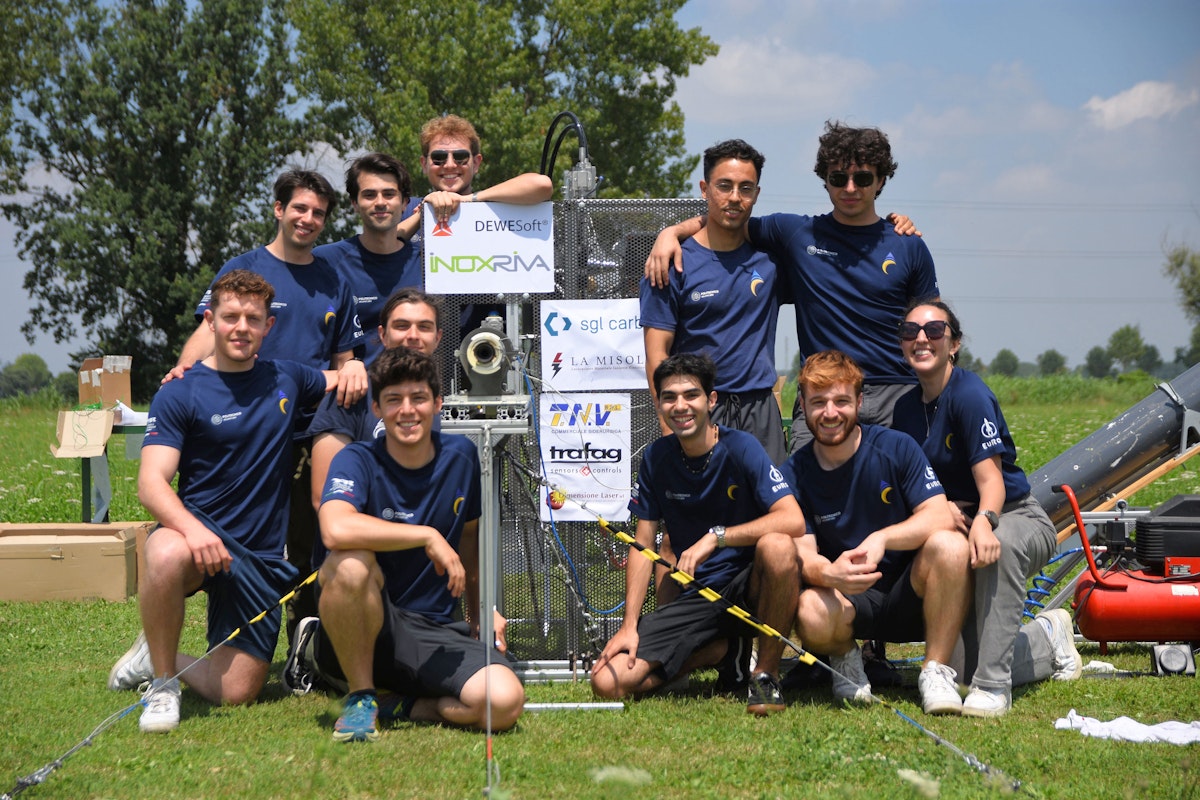
Skyward Experimental Rocketry is a student association founded in 2012 at Politecnico di Milano (PoliMi), Italy. It enables students to delve deeper into topics covered in class by competing at the international level. Skyward has around 170 members and external advisors, of whom a few fewer than 100 are actively working on ongoing projects.
Each year, the team participates in EuRoC, a European annual competition for experimental rocketry. It is organized by the Portuguese Space Agency in collaboration with several private industries from the aerospace market.
With two first places and several prizes under its belt, the Skyward team has never turned away new challenges. This latest project symbolizes the will of the association and the propulsion department to tackle a new kind of engine and a new technology.


The bi-liquid rocket engine
Chemical rocket engines operate by converting the chemical energy stored in a fuel and an oxidizer into a high-velocity exhaust gas that is ejected from the system, creating thrust.
The difference between solids, hybrids, and bi-liquids is primarily in the way the fuel and oxidizer are stored:
Solid engines: Present a solid charge where fuel and oxidizer are pre-mixed. Once we ignite this charge, it is nearly impossible to extinguish it, and we cannot perform throttling.
Hybrid engines: Representing a step-up in terms of flexibility, these engines store either the fuel or oxidizer in a tank in liquid or gaseous form, while the other component is in solid form inside the chamber. As a result, they can be shut off and re-ignited. Throttling is also possible.;
Bi-liquid engines: As the name suggests, store both oxidizer and fuel in liquid form. They offer the most significant operational flexibility, combining all the convenient features of hybrid propulsion (re-ignitability, throttle ability) with the best performance in terms of efficiency and maximum thrust.
So, why build a bi-liquid rocket engine? While such an advanced engine is not necessary for the modest apogee requirements of the competition, Skyward's goal has always been to empower students to put their knowledge into practice. This mission, coupled with an effective knowledge transfer between senior and junior members, results in projects that steadily advance in their technical level.
The Aeneas engine operates with nitrous oxide as an oxidizer and ethanol as a fuel. We store both in SRAD (Student Researched and Developed) aluminum tanks, which, after the refueling phase, are pressurized with nitrogen stored in a commercial vessel.
In broad terms, the phases that make up a test are:
Facility assembly and preparation
Engine and electronics integration: We integrate the engine and all related components in the test facility, and the control and acquisition hardware are integrated and tested.
Refueling: After everything has been assembled and checked, we perform refueling of ethanol and nitrous oxide, followed by the pressurization of the tanks via nitrogen.
Firing: When we have completed all checks and previous operations, we fire the engine.
Putting in safety: After the firing, we depressurize all systems and disconnect the storage vessels.
Performance evaluation: We analyze the data acquired to assess performance metrics.
Of these phases, five out of six require some acquisition and control system. That is where Dewesoft comes in. All the hardware and software responsible for these operations fall under the name "Ground segment avionics."
Ground segment avionics
We use the ground segment avionics to interface all the various subsystems together. It is of paramount importance as it enables data acquisition and control during tests of all kinds.
Typically, Skyward develops its avionics system, from the software to the hardware; this project is an exception.
System requirements
First, we list the requirements for the ground segment avionics subsystem:
Functional
able to actuate eight pneumatic valves
able to power the igniter
able to read 11 pressure transmitters
able to read one load cell
able to read eight thermocouples
able to read one current
System
remotely operated
Performance
able to acquire all available channels at the same time, with a rate of at least 100 Hz (or lower when limited by the transmitter itself)
Platform choice
We will primarily cover our entire list of requirements using a programmable logic controller (PLC) and a data acquisition system (DAQ). After a brief review of the most common solutions available in the market, the one that stood out was IOLITE.
The reasons behind this choice are numerous, but we can summarize these in two categories: 1) the system's hardware and software capabilities, and 2) previous experience and relationships with Dewesoft.
Dewesoft has been the DAQ of choice for propulsion ground testing measurements in Skyward since 2022. During this period, the team gained extensive experience with both hardware and software and had the opportunity to verify the high quality of the devices.
The devices used so far, Dewesoft IOLITE 6xSTG and IOLITE 8xTH, were, however, only used for passive data acquisition, whereas for the project at hand, control is also a requirement. Luckily, the IOLITE lineup features digital output modules.
In conclusion, the ongoing relationship with and years of successful use of Dewesoft's devices made it the most logical choice.
Rocket Testing System Architecture
After reviewing the various available devices and discussing with the Dewesoft team, we selected the IOLITE R8 chassis, equipped with:
IOLITEir-8xTH module
IOLITEr-16xLV module
IOLITEir-32xDO module.
These modules enable the device to carry out all measurements listed in the requirements and, simultaneously, provide a digital output interface to address the control needs. IOLITE modules also offer high sampling rates up to 20 kHz per channel.
The pneumatic valves in use in the test facility require, as the name suggests, compressed air to operate. We can carry out this operation using solenoid valves to shut on and off a compressed air circuit.
Finally, the igniter requires a DC to power a nichrome wire, which, by the Joule effect, will ignite the pyrotechnic charge. Figure 1 shows the proposed schematics for the ground segment avionics.


The system shown is composed of:
A PC running DewesoftX to control the IOLITE R8,
The IOLITE R8 unit,
A pneumatic box to house all solenoid valves that, once activated, provide the pneumatic valves (included inside the "test facility") with compressed air; this box would also contain the power supply and current shunt for the igniter, and
The test facility houses the engine, fluidics lines, and all devices needed to operate them.
Expansion board
While the 16xLV module provides enough inputs to accommodate all the transmitters listed in the requirements, it is not directly compatible with the transmitters used.
This specific module is capable of reading voltages in the 10 V and 200 V ranges, while the pressure transmitters employed have an output in the 4-20 mA range and require external excitation.
Moreover, while the 32xDO module is capable of sinking 0.5 A in "switch" mode, it can only provide 2 A to the user. Refer to the DewesoftX Software User Manual for instructions on configuring Digital Out in DewesoftX. This current is insufficient to power all valves simultaneously.
To provide more power, an external power supply is needed. Then, unless we connect the IOLITEs and external power supply to the same ground, relays of some kind would be necessary to control the solenoid valves.
Finally, we expect the igniter itself to draw anywhere from 2 A to 5 A, making a relay necessary.
It is then clear that some external expansion board is needed to interface the IOLITE modules to the rest of the avionics. We compiled a brief list of requirements that this board must satisfy.
The expansion board shall:
Functionality
Be able to provide excitation to 11 pressure transmitters
Be able to read the current outputs from 11 pressure transmitters
Be able to control 8 (valves) + 1 (igniter) external loads
Be powered with the available output provided by the IOLITE modules
Provide excitation to the load cell
System
Physically and electronically integrate with the IOLITE modules
Shall use easy-to-operate connectors
Shall not interfere electrically with the IOLITE chassis
Performance
Maximize the voltage input range for each transmitter
We then designed the board following the requirements, resulting in a PCB with four main sections:
24V power is provided by the IOLITE modules (with the relative decoupling capacitor), and this voltage is fed directly to the pressure transmitters. The current required by the transmitter then flows through the 499Ω shunt resistor. This value is selected to maximize the 10 V range of the analog input on the IOLITE. While technically the shunt should be 500 Ω, the 499 Ω variant costs significantly less when 0.01% accuracy is required. This section covers 12 out of 16 of the 16xLV input channels; the other four we leave as simple voltage readings.
Once again, the 24V power provided by the IOLITE modules is routed to power a series of solid-state relays. We then sink this power into the digital output pins of the 32xDO module. Whenever a channel of this module is activated, the relay is activated, and the circuit on the other side, i.e., the solenoid valves, is closed. 1 kΩ resistors are placed in series with the relays to ensure a proper voltage supply.
Here, in the same fashion as the second section, relays are connected to the 32xDO module. Figure 2 shows that we just mounted one. This time, the relay is mechanical and thus requires a diode between its inputs; additionally, we feed it directly 24V. We used this component to switch the power driving the igniter in place of the solid-state counterpart because of its higher current limit.
The final section features a charge pump and related components. Here, the mains voltage is reduced to 5V using an LDO regulator, which powers the charge pump that outputs ±5V to power the load cell.


The test campaign
The ultimate goal of the project is to test and validate the engine, which we carry out by performing so-called Static Fire Tests (SFTs). Figure 4 shows the test bench, which houses the propellant tanks, engine, and all piping required for both the refueling and firing phases. Moreover, it contains all the acquisition and control hardware described so far.

| POSITION | PHYSICAL QUANTITY | MODEL | RANGE |
|---|---|---|---|
| Venturi (oxygen and fuel) location 1,2 | Pressure | Trafag NAT 8252 | 0 ÷ 100 bar |
| Tank top (oxygen and fuel) | Pressure | Trafag NAT 8252 | 0 ÷ 100 bar |
| Nitrogen refuel line | Pressure | Trafag NAT 8252 | 0 ÷ 250 bar |
| Nitrous oxide refuel line | Pressure | Trafag NAT 8252 | 0 ÷ 100 bar |
| Combustion chamber | Pressure | Trafag NAT 8252 | 0 ÷ 40 bar |
| Nitrogen (oxygen and fuel) regulator | Pressure | Trafag NAT 8252 | 0 ÷ 250 bar |
| Engine | Mass | Mavin NA2 | ±350 kg |
| Venturi (oxygen and fuel) location 1,2 | Temperature | TC-direct 405-010 | Type K |
| Engine | Temperature | RS PRO exposed junction | Type K |
Data acquisition and control setup
The DewesoftX setup employed reflects the two main phases of the test: refueling and firing. We designed two different displays, both accessible simultaneously, using a multiple-monitor setup.
Figure 6 shows the first display presenting “Recorder”, “Digital meter”, and “Input control” widgets alongside text boxes to increase clarity during operations.
The input controls directly link to the digital output channels on the 32xDO module, which, in turn, operate the relays present on the expansion board. We set some input controls to the “Switch” type, while others to “Push button”; this choice reflects the nature of the operation control.
The inputs we operate via push buttons are the venting of the fuel and oxidizer tanks; these valves most often need to be operated in short bursts, a task that is more easily achievable with the push-button interface. Nonetheless, even during acquisition, we can change these to accommodate switches or other types of input if necessary.
Once one of these inputs is activated, the circuit powering the relays on the expansion board closes, thereby activating the connected device.


Figure 7 shows the second display used during the fire test operations. It is not dissimilar from the other; it adds “Lamps” to easily monitor the status of critical valves that we need to observe during the test, alongside a “Digital meter” for temperature control.

Finally, to achieve correct ignition, we must open the oxidizer valve ~250 milliseconds after the fueling. If this sequence is not respected or if the timing is off by a significant margin, there is a risk that the oxidizer reaches the chamber before the fuel, allowing it to start exothermically decomposing and possibly leading to an explosion. This sequence is thus of utmost importance.
The operator cannot reliably perform such an operation. Thus, it is automated.
Figure 8 shows a custom “User inputs” named “FIRE”; we will use this control for the automation of the ignition sequence.


Consequently, we create a “FIRE_DELAYED” channel using the “Math” module; this channel is essentially the FIRE signal delayed by 250 milliseconds.


Finally, the automation sequence is programmed using the “Alarms” module. Whenever the operator activates the FIRE channel via a switch, the MAIN_FUEL valve is activated. 250 milliseconds later, the FIRE_DELAY channel and MAIN_OX are also activated.
Both valves are then shut off automatically after a set time.


Test results and data post-processing
After some initial testing and debugging, the team successfully tested the engine and its support systems. The data acquisition and control systems performed as expected, recording all data correctly within specifications.
As the primary goal of this test campaign was to assess the engine performance, we can derive most parameters of interest from chamber pressure, oxidizer, and fuel mass flow rates, and thrust.
First, we exported the raw data to a suitable format using DewesoftX. Then, we select the period of interest and fit the resulting data.
We then use the fitted data to compute the aforementioned parameters of interest, for example, calculating the mass flow rate using the pressure and temperature data measured from a custom venturi.
One of the main advantages of a pressurized bi-liquid engine is that, if operated correctly, it can maintain nearly constant chamber pressure, thereby providing roughly constant thrust. Figures 12 and 13 illustrate this; after an initial transient (deliberately prolonged for ignition purposes), the pressure and thrust remain almost constant.


After computing the oxidizer and fuel mass flow rates, we calculate the OF (oxidizer-to-fuel ratio). This parameter is of paramount importance for evaluating the correct design of the injectors and assessing engine efficiencies; Figure 14 illustrates this.

Finally, we can derive the combustion efficiency defined as:
Where is the characteristics velocity efficiency, is the combustion chamber pressure, is the nozzle throat area, m is the total (oxidizer and fuel) mass flow rate, and is the theoretical characteristic velocity, and is computed via chemical equilibrium solvers—figure 15 presents thus the equation’s only unknown, .

The value averages, not considering the initial transient, are slightly below 80%, on the lower side of the expected range for this parameter. This occurrence could be due to imperfect mixing between the oxidizer and fuel, but even a slight overestimation of the mass flow rate can drastically decrease this efficiency.
As the thrust and pressure perfectly match the design values, model errors and various assumptions likely lead to an overestimation of the mass flow rate.
Conclusion and future development
Despite its issues and setbacks, we successfully conducted nominal static fire tests and validated the design from various standpoints.
The implementation and use of Dewesoft as a data acquisition and control system were very successful, enabling safe and reliable testing.
At the time of the writing of this case study, the team is already implementing another iteration of the engine, this time completely 3D printed and regeneratively cooled.
Dewesoft will once again be the choice for the avionics. This time, we aim to implement more complex control algorithms utilizing the C++ functionalities built into DewesoftX. However, at the time of writing, it is not yet possible to directly control digital output channels via the plugins.
We owe a deep thank you to the Dewesoft Italy team, as always, they have been incredibly available to help us in our endeavors, without them, this project would not have been possible.


Based on original work by (alphabetical order):
Chiara Conte, Team Member, Master's degree in Space Engineering
Gabriele Del Pelo, Team Member, Bachelor's degree in Aerospace Engineering
Daniele Fabbris, Project Manager, Bachelor's degree in Aerospace Engineering
Christian Ferracane, Team Member, Bachelor's degree in Aerospace Engineering
Lorenzo Giaretta, Team Member, Bachelor's degree in Aerospace Engineering
Lorenzo Loria, Team Member, Bachelor's degree in Aerospace Engineering
Francesco Miccoli, Integrated Project Team Leader, Master's degree in Space Engineering
Simone Modelli, Team Member, Master's degree in Space Engineering
Simone Nannetti, Team Member, Bachelor's degree in Aerospace Engineering
Edoardo Nistri, Team Member and Advisor, Master's degree in Materials Engineering
Marco Sangiorgi, Team Member, Bachelor's degree in Aerospace Engineering