


How NASA Tested the Space Shuttle: Ground Testing, Avionics, and Data Acquisition Explained

June 4, 2025
The Space Shuttle program was one of the most ambitious engineering projects in history, combining the complexities of a reusable spacecraft, advanced propulsion systems, and cutting-edge avionics. Central to its development was a rigorous testing regimen, emphasizing data acquisition to validate designs, ensure safety, and refine performance. This article explores the multifaceted testing processes of the Shuttle's engines, structures, and avionics, highlighting the facilities and key methodologies employed.
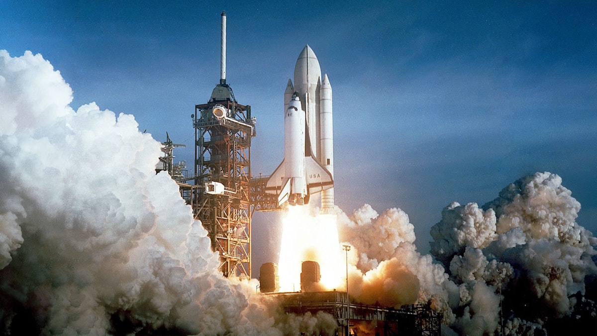
A new chapter in manned space flight begins
The US Space Shuttle program was developed to create a reusable spacecraft that could reduce the cost of space access and support a wide range of missions, from satellite deployment to space station servicing.
Initiated in the early 1970s, the program responded to the need for a more versatile and cost-effective alternative to expendable rockets. The decision to pursue the Shuttle was made under President Richard Nixon’s administration in 1972, following recommendations from NASA leadership and advisory panels focused on long-term space infrastructure going back to 1969.
It was officially named the Space Transportation System, or STS. Key figures such as NASA Administrator James C. Fletcher and engineers like Maxime Faget played crucial roles in shaping the Shuttle’s design and goals.
Backed by the Department of Defense and commercial satellite interests, the Space Shuttle was envisioned as the cornerstone of America’s post-Apollo space ambitions. Nine years after funding was approved in 1972, the first mission (STS-1) launched in April 1981 and orbited the Earth for two days. The Shuttle’s unique design, featuring a reusable orbiter, solid rocket boosters, and an external fuel tank, marked a major engineering leap in crewed spaceflight.
Space Shuttle testing was critical to program success. New sensors and test stands had to be designed or refitted to support testing new technologies. Let’s examine the main testing initiatives undertaken during the development of the US Space Shuttle.
Testing the Space Shuttle main engines (SSMEs)
The RS-25 Space Shuttle Main Engine (SSME), developed by Rocketdyne (later part of Pratt & Whitney and now Aerojet Rocketdyne), was the first reusable liquid-fueled rocket engine. Each orbiter was equipped with three SSMEs, and testing them required facilities capable of handling their immense power and complexity. NASA's Stennis Space Center in Mississippi became the primary site for SSME testing, utilizing test stands A-1 and A-2, which were built originally for the Apollo program.
NASA’s RS-25 engine tests were among the most rigorous propulsion system testing in aerospace history. Designed for reuse and performance under extreme conditions, these engines were vital to the success and safety of the Space Shuttle program.


Engine component testing
In the 1970s, Rocketdyne performed SSME component testing under NASA’s direction. High-pressure turbopumps were tested for cavitation, vibration, and performance in cryogenic temperatures. Injectors and combustion chambers were hot-fire tested to ensure stable mixing and ignition of hydrogen and oxygen. Specialized materials were tested for thermal fatigue and hydrogen embrittlement resistance.
Testing was performed at NASA’s Marshall Space Flight Center (MSFC) in Huntsville, Alabama. In addition, extensive bench and rig tests of subcomponents were conducted at Rocketdyne’s facilities in Canoga Park, California.
Full-scale hot-fire testing
Once integrated, each complete SSME was subjected to full-duration hot-fire tests simulating the entire launch burn (over 500 seconds). These tests assessed:
Start-up and shutdown transients.
Performance at power levels from 65% to 109%.
Thrust stability, vibration, and thermal response.
Fuel and oxidizer flow dynamics.


Engine tests were performed on the B-1/B-2 test stands at NASA’s Stennis Space Center (SSC) in Mississippi. Thousands of tests were conducted to identify thermal margin limits and refine flight configurations. Later, in the 1900s, Block I and II engine turbopump upgrades were again tested at Stennis.
From 1975 to 2009, Stennis conducted 2,344 SSME tests, accumulating over 820,000 seconds of hot-fire data. These tests were critical in validating engine performance, identifying issues, and implementing improvements.
Gimbal testing: thrust vector control (TVC)
In addition to hot firing tests, Stennis conducted gimbal testing. The Shuttle's main engines gimbaled, meaning they could be “steered” in two axes. This was important for steering the spacecraft, especially since its center of gravity constantly changed because of fuel consumption and other factors. The video below shows an actual gimbal test:
Engines were hot-fired while actively gimbaled in simulated flight profiles, including circular and rapid angular patterns. These tests were designed to validate actuator response times, structural flexibility, and thrust vectoring software control loops.
The Fred Haise Test Stand at Stennis has recently been upgraded, especially for RS-25 gimbal testing for NASA’s current Artemis program. In 2023, an RS-25 was gimbaled during a 720-second hot-fire, confirming the engine's capability for precise and prolonged steering input under flight conditions.
Flight readiness firings and post-flight testing
Before each Shuttle launch, engines underwent Flight Readiness Firings (FRFs) on the launch pad at NASA’s Kennedy Space Center. After each flight, the engines were disassembled and inspected for cracks, seal wear, and thermal erosion. The SSMEs could be used seven or eight times despite extreme heat and pressure.


Data acquisition was paramount across the full gamut of engine testing. Sensors measured parameters such as pressure, temperature, vibration, and thrust. Advanced diagnostics, including exhaust plume spectroscopy, were employed to detect anomalies and assess combustion efficiency.
In later years, testing the RS-25 engines involved collecting up to 13.17 billion data points during a 500-second test, utilizing 256 high-speed and 512 low-speed channels. Four RS-25 engines are used in the SLS (Space Launch System) for NASA’s current Artemis program. The testing program was a collaborative effort between NASA and contractors. Shuttle flight readiness firing was critical to mission success.
"This is a remarkable accomplishment and is a tribute to every member of the NASA and Boeing test team at Stennis."
~John Plowden, vice president and program manager for the SSME at Boeing
Structural and vibration testing at NASA facilities
Structural test article (STA)
NASA used the Structural Test Article (STA) as a critical step in validating the design and durability of the Space Shuttle orbiter before the vehicle ever flew. The STA was a full-scale, non-flight version of an orbiter named OV-099. It was built primarily to undergo structural tests at NASA’s Marshall Space Flight Center in Huntsville, Alabama.
The STA was subjected to rigorous mechanical loads to simulate the stresses and forces experienced during launch, ascent, orbit, re-entry, and landing. Using massive hydraulic actuators, engineers applied thousands of pounds of pressure to simulate normal flight conditions and extreme, off-nominal scenarios. These tests were designed to verify that the orbiter’s aluminum airframe, thermal protection system (TPS) mounts, and landing gear structures could withstand the complex and variable loads across all mission phases.
One notable test involved applying bending and torsion forces to simulate the pressure from the external tank attachment during launch. Engineers also tested the durability of the wing and fuselage connections, payload bay doors, and forward fuselage structures. Shuttle structural testing was vital to ensuring safety and mission reliability, especially because many parts of the shuttle’s airframe had never been flown before in such a configuration.


After completing the STA testing in 1979, OV-099 was returned to Rockwell International’s facility in Palmdale, California. Rather than being retired, it was retrofitted into a full-flight vehicle and renamed Challenger. It would fly nine successful missions before its tragic loss during mission STS-51L in 1986.
Wind tunnel testing
In the 1970s, the U.S. Space Shuttle underwent extensive wind tunnel testing to verify its aerodynamic properties during all phases of flight:
launch,
ascent,
orbital maneuvering,
re-entry, and
landing.
Because of the Shuttle’s radical design – a reusable orbiter with delta wings mounted alongside an external tank and solid rocket boosters – it presented unprecedented aerodynamic challenges. NASA collaborated with major research centers and contractors to perform hundreds of Shuttle wind tunnel tests across various scales and configurations:
NASA Ames Research Center,
NASA Langley Research Center,
NASA Marshall Space Flight Center,
Rockwell International.


More than 100 wind tunnel models were built, ranging from small-scale orbiter mockups to large, complex models of the entire launch stack. These were tested at speeds ranging from subsonic (Mach 0.2) to hypersonic (up to Mach 20) to simulate various atmospheric conditions. Each test helped refine the orbiter’s thermal protection system placement, control surface effectiveness, and stability.
NASA wind tunnel testing also evaluated the separation dynamics of the SRBs and external tank, which was a particularly complex problem due to potential asymmetric airflow during staging.
One landmark facility involved in this effort was the Unitary Plan Wind Tunnel at NASA Ames, where hypersonic testing helped define the heat shield shape and nose cone angles. Meanwhile, Langley’s 16-Foot Transonic Tunnel refined the Shuttle’s low-speed handling and approach characteristics during unpowered descent and landing. The data obtained from these wind tunnel campaigns was vital in informing design iterations and ensuring that the Shuttle could fly safely through all flight regimes.
The Saturn V test stand
Between 1978 and 1979, NASA conducted extensive dynamic testing of the Space Shuttle. These were performed at the historic Saturn V Dynamic Test Stand (the Dynamic Structural Test Facility) at NASA’s Marshall Space Flight Center in Huntsville, Alabama.
Initially built for Saturn V rocket testing during the Apollo program, the facility was repurposed to evaluate the Space Shuttle.
The purpose was to ensure that the integrated stack, including the external tank, orbiter, and two solid rocket boosters, would endure the mechanical stresses of launch and flight. The 363-foot-tall (110.6 m) facility allowed engineers to apply dynamic loads and vibrations to the orbiter, simulating flight conditions and identifying potential structural issues.
 for Mated Vertical Ground Vibration tests (MVGVT).")

Dynamic testing simulates the vibrations, oscillations, and acoustical loads a launch vehicle experiences during various flight stages. NASA engineers used the Saturn V test stand to mount a full-scale configuration of the Shuttle vehicle, including the Structural Test Article (STA) orbiter OV-099, a test external tank, and test versions of the SRBs. The goal was to identify structural resonances or potential failure points by subjecting the vehicle to simulated flight vibrations, particularly those caused by engine thrust and aerodynamic buffeting during ascent.
Hydraulic shakers and other actuators introduced controlled oscillations across the Space Shuttle stack. These tests confirmed the integrated vehicle's natural frequencies and ensured no dangerous resonance modes were encountered during launch. As a result, engineers refined flight control software and made minor design adjustments to dampen vibrational loads.
The dynamic test campaign was vital in certifying the Space Shuttle for flight. It marked one of the final phases of ground testing before the Shuttle’s first orbital mission, STS-1, in April 1981. Using the Saturn V stand for Shuttle testing symbolized the continuation of Apollo-era infrastructure into the next era of American spaceflight.
Learn more about modal testing and sine reduction test:


Shuttle avionics integration laboratory (SAIL)
The Shuttle Avionics Integration Laboratory (SAIL) was a crucial facility at NASA’s Johnson Space Center in Texas. It was the primary testbed for verifying the Space Shuttle’s avionics and flight software before each mission.
SAIL housed a high-fidelity, full-scale replica of the Shuttle’s flight deck and avionics systems, often called a “hardware-in-the-loop” simulator. It included actual flight computers, displays, data buses, and control panels identical to those used aboard operational orbiters. This allowed NASA engineers and flight crews to test, validate, and troubleshoot the software and hardware configurations for every Shuttle flight in a highly realistic and controlled environment. SAIL housed a complete avionics mock-up of the orbiter, designated OV-095, allowing for comprehensive verification tests.


SAIL's testing process was extensive and rigorous. The facility contained Firing Room Launch Equipment identical to that used at Kennedy Space Center, enabling complete ground verifications, countdown, and abort operations. The software on the Shuttle was often considered among the most bug-free of operational systems.
OV-095 was built with an orbiter cockpit with all the controls, computers, wiring, and software identical to an actual orbiter. One of SAIL’s most important roles was performing mission verification testing, running simulated launch, orbit, and landing scenarios using the exact software build planned for a given mission.
SAIL’s shuttle avionics integration helped identify potential bugs, logic errors, or hardware compatibility issues before flight, ensuring mission safety and success. Because the Shuttle’s software was so complex (over 400,000 lines of code in its main flight control system), SAIL's exhaustive testing procedures were a cornerstone of the Shuttle program’s safety culture. It remained operational throughout the program, even helping test return-to-flight updates after the Challenger and Columbia disasters.
Integration testing at the VAB
While not a conventional testing facility, NASA’s VAB (Vehicle Assembly Building) at the Kennedy Space Center in Florida was the site of several essential integration checks and readiness verifications. The orbiter, solid rocket boosters (SRBs), and external fuel tank were vertically stacked inside the VAB, and engineers conducted interface checks to verify mechanical and electrical connections between elements. This included verifying umbilicals, hold-down bolts, alignment, and stage mating procedures. A Vehicle Assembly Verification Test (VAVT) confirmed the mechanical, pneumatic, and electrical integration of the fully stacked Shuttle.


Next, pre-rollout checks were performed on environmental controls, purge systems, and various avionics to verify readiness before rollout on the mobile launcher platform.
Transportation checks ensured the Shuttle’s structural stability during rollout to the launch pad. Laser alignment sensors and strain gauges monitored the Shuttle during the roll-out process.
Flight and landing testing at NASA Dryden
NASA’s Dryden Flight Research Center (now NASA Armstrong) was pivotal in developing and operationally testing shuttle landing, particularly during its early flight validation and recovery phases. In 1977, Dryden hosted the Approach and Landing Tests (ALT) using the prototype Space Shuttle Enterprise, which was released from a modified Boeing 747 Shuttle Carrier Aircraft to verify the orbiter’s unpowered gliding and runway landing capabilities. Dryden performed orbiter approach and landing tests numerous times.
These tests validated critical aerodynamic, control, and landing systems while providing essential training for astronauts and flight engineers. Throughout the Shuttle program's operational lifespan, Dryden also served as a primary landing site at Edwards Air Force Base, where it supported telemetry during reentry, managed post-landing inspections, and prepared orbiters for return transport to Florida.
In 1977, the NASA 747 Shuttle carrier aircraft and five T-38 aircraft flew over the shuttle Orbiter 101 "Enterprise" while it was parked on the runway at Edwards Air Force Base in Southern California—photo by NASA.
NASA Dryden also extensively researched the shuttle's Thermal Protection System (TPS). Using aircraft such as the F-104 and F-15, engineers tested TPS tiles under various aerodynamic and atmospheric conditions to ensure they could withstand the intense heat of re-entry. Additionally, tests on a modified CV-990 aircraft improved shuttle tires and brakes, allowing for higher crosswind landing limits and prompting resurfacing of the Kennedy Space Center runway for enhanced tire wear.
NASA Dryden contributed to aerodynamic testing, control system development, and simulation modeling, enhancing the Shuttle's reentry and landing performance. Its contributions were essential to the Shuttle’s success in transitioning from a spacecraft to a glider for safe Earth returns.
On April 14, 1981, the first shuttle mission, STS-1, ended with a successful landing at Edwards Air Force Base. In total, 54 shuttle landings occurred at Edwards, with NASA Dryden managing and coordinating facilities, systems, and ground servicing equipment to support these missions.
Specialized sensors
NASA called on leading manufacturers to develop sensors especially designed for the Space Shuttle. Monitoring the cryogenic propellants in the Shuttle's external tank was critical.
Scientific Instruments developed silicon diode temperature sensors capable of detecting minute temperature variations in extremely cold environments. These sensors were hermetically sealed in stainless-steel enclosures to withstand the harsh conditions of spaceflight and were essential in preventing fuel boil-off and ensuring the integrity of the propulsion system.
In parallel, Honeywell engineered silicon piezoresistive pressure transducers for the Space Shuttle Main Engines (SSMEs). These devices converted pressure-induced strain into electrical signals, providing real-time data on engine performance. Their integration of multiple functions on a single chip enhanced reliability and facilitated precise monitoring of combustion chamber conditions.
NASA employed wireless sensors from MicroStrain to monitor vibroacoustic shock during Shuttle launches. These sensors measured the intense vibrations and acoustic energy generated at liftoff, providing data to assess potential impacts on spacecraft integrity and ground facilities. The information gathered aided in refining predictive models and enhancing launch safety protocols.
How Dewesoft enhanced NASA’s telemetry processing
In 2008, NASA's Launch Control Center (LCC) at Kennedy Space Center initiated a modernization of its aerospace telemetry systems. Dewesoft was selected to provide a solution to handle the increasing complexity and volume of data from various spacecraft systems.
Dewesoft 7 (predecessor of the DewesoftX software) in conjunction with Dewetron computers and Pulse Code Modulation (PCM) telemetry cards, enabled the encoding of analog and telemetry data into serial digital formats suitable for long-distance transmission. This upgrade was crucial for processing over 200,000 channels of Ethernet data in real-time, including data from PLC boosters, main engines, umbilical controls, rocket avionics, and capsule telemetry links.
Real-time data processing capabilities
DewesoftX's advanced features allowed for:
Real-time plotting and retrieval: Operators could monitor data in real-time in the Firing Room or via remote connection.
Troubleshooting tools: The system provided real-time and near real-time tools for vehicle and payload troubleshooting.
Data translation: Data fusion and persistent data storage capabilities transform raw data into actionable information.
Digital storage and file transfer: Analog data could be digitally stored and transferred efficiently.
Bit-level analysis: The system supported real-time or post-test bit anomaly detection and measurement scaling.
Integration with IRIG 106 Chapter 10 standards
Dewesoft telemetry inputs are compatible with IRIG 106 Chapter 10 standards, allowing it to read and decode telemetry data from various sources, including:
PCM Data: Both unpacked and packed formats.
MIL-STD-1553 and ARINC-429: Common aerospace bus data protocols.
iNET data recording: Up-to-date telemetry standards.
Video: Standard and high-speed video.
Ethernet & UART channels: For comprehensive data acquisition.
This compatibility ensured seamless integration with the existing NASA telemetry infrastructure.
Dewesoft's advanced data acquisition systems and software have significantly enhanced NASA's real-time ability to process and analyze vast amounts of telemetry data. Their integration into NASA's testing and launch operations has contributed to the safety and success of missions during the later stages of the Space Shuttle program and beyond.
For a visual demonstration of Dewesoft's role in monitoring Space Shuttle launches, you may find the following video informative:
The Dewesoft systems installed at NASA are still in operation today and are used frequently for ongoing operations, including the Artemis program and others.
Related articles and supporting information
Learn more about the Dewesoft PCM telemetry solution


Conclusion
The development and success of the Space Shuttle program hinged on one indispensable factor: data.
NASA Data acquisition was at the heart of every milestone, from the searing heat of RS-25 hot-fire tests to the simulated silence of orbital reentry in wind tunnels and structural rigs. NASA and its partners created one of the most extensive and sophisticated aerospace testing infrastructures in history, supported by advanced sensors, telemetry systems, and software, many of which, like DewesoftX, continue to support modern programs such as Artemis.
These rigorous ground tests verified component performance and safeguarded astronauts’ lives across 135 missions. Ultimately, the Space Shuttle stands as a testament to how engineering ambition, validated through relentless testing and precise data collection, can push the boundaries of human spaceflight.
References
NASA Stennis Powers Nation’s Space Efforts – Past, Present, Future. NASA.
Rocket Engine Plume Diagnostics at Stennis Space Center. NASA Technical Reports Server (NTRS).
Data Tells the Story of NASA's Moon Rocket Engine Tests. NASA.
NASA. “NASA Tests Critical In-Flight Capability During RS-25 Engine Hot Fire.”
NASA. “Stennis Space Center Completes Upgrade to Critical Test System.”
Chaffee, L. The Space Shuttle: Celebrating Thirty Years of NASA's First Space Plane. Smithsonian Books, 2002.
NASA. (2021) The RS-25 Engine: Lineage of the Space Launch System Powerhouse.
ResearchGate diagrams:
Jenkins, Dennis R. (2001). Space Shuttle: The History of the National Space Transportation System. Specialty Press.
Toward a History of the Space Shuttle: An Annotated Bibliography