


Automated Motor Gear Testing and Quality Control

September 1, 2020
Electric park brakes (EPB systems) can now be considered a subset of Brake-by-wire technology and they are generally functioning with the actuator - Motor Gear Unit – an MGU, i.e. EPB Actuator.
The reliability of MGU is definitely a key factor in proper function and EPB assembly. Award-winning DewesoftX software and turn-key data acquisition devices can be beneficially applied to automated quality control as an integrated verification measure for MGU manufacturers.
Electric park brakes are used in passenger vehicles to hold the vehicle stationary on grades and flat roads and are recently more and more equipped as default facilities for modern cars. This functionality was traditionally accomplished using a manual parking brake.
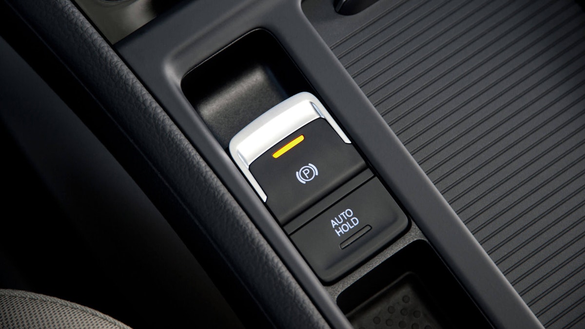
In recent years, with electric park brakes, the driver activates the holding mechanism with a button and the brake pads are then electrically applied onto the rear brakes.
The electric or electronic parking brake (EPB), also known as an automatic parking brake (APB), is an essential function offering the driver increased comfort and convenience. In addition, as the hand lever is not used, car manufacturers have more freedom of choice as to where they site the operating parts within modern cars.
This electric parking brake function has a multitude of uses besides deactivating and activating the brakes, such as hill- or auto-hold. Hill-hold stops the car rolling away accidentally when standing still or setting off. Auto-hold keeps the brake pressure applied after the driver releases the pedal. In case the ABS sensors detect any movement, the brake pressure is increased. If the accelerator is pressed - or the clutch released on a manual - the brakes are accordingly let off.
Recently, there are two main parking brake systems in use namely the cable-pull and electric-hydraulic type. Both methods include a visual warning light on the dashboard. The second of these is now the most common. A third full-electric type will start to be used in the near future.


Electric-hydraulic caliper systems are usually employed as part of a larger control system such as an electronic stability program (ESP). The EPB system is electronically controlled and consists of the EPB switch, the EPB caliper, and the electronic control unit (ECU), wherein the Motor Gear Unit (MGU, i.e. EPB Actuator) is equipped with a caliper which is operated by the signal from the ECU through simple switch touch.
When the driver presses the switch to activate the parking brake, the ESP unit automatically generates pressure in the braking system and presses the brake pads against the disc. The calipers are then locked in position by an electrically controlled solenoid valve. The caliper remains locked without any need for hydraulic pressure. To release the brake, the ESP briefly generates pressure again, slightly more than was needed to lock the caliper, and the valve is released.
It has been widely verified that EPB normally takes up less space and automatically disengages when driving – useful for driving in heavy traffic and parking on hills. Obviously, it will provide better assistance to the driver and has now been introduced by multiple vendors.
Issue and measurement application
In this case, the end-user - located in Shenzhen, China – is an MGU assembly supplier to the leading e-mobility manufacturer BYD Auto, who was concerned about the MGU quality assurance and constantly searching for a robust statistical way to sort out unqualified MGU before the final products rolled off the assembly line. The qualification of this sub-system is critical in determining the reliability of EPB assembly.
A subjective method to detect defective parts is the perception of noise, which physically derives from abnormal vibrations. Such noise was previously roughly spotted by a QC inspector’s ear empirically - in general, the noise under operation significantly differs from that of qualified units
At the present time, in consideration of consistency and accuracy, and since the sound test in situ is not applicable, the manufacturer endeavors to introduce quantitative methods for verification. Instead of by simple auditory assessment, the task is then likely to be handled through an understanding of the vibration pattern.
Acceleration (vibration) measurement is more practical than an acoustics scheme for on-site operation. This vibration pattern physically reveals interior defections. In this case, it concerns the vibration along X, and Y directions where the Z-axis of the built coordinate is perpendicular to the MGU cover
In practice, the verification comes without ready-to-use compliances or references. That is to say, the user is likely to collect multiple contrast tests between un- and qualified products uncovering numerical differences in spectra.
Testing solution setup
This application is a project, through which the Dewesoft DAQ system and test system are placed in a cabinet on-site, being integrated into a test bench to monitor accelerations of each MGU as effective QC measures. The facility will be working as a station in an assembly line to conduct product quality validation.
Automation is necessarily implemented with a programmable logic controller (PLC) - an industrial digital computer that has been ruggedized and adapted for the control of manufacturing processes, such as assembly lines, in this case, a SIMATIC WinCC® from SIEMENS.
Manufacturing processes are becoming more and more complex due to increasing quality requirements coupled with fast product changes and frequent modifications. To ensure the highest possible productivity at the same time, it has to be possible to make prompt, target-oriented decisions regarding process optimization at all levels within a company. This requires an integrated flow of information across all operating levels and locations.
SIMATIC WinCC® is a scalable process visualization system, including what is generally called Supervisory Control and Data Acquisition (SCADA), which is commonly used to monitor and control fully automated physical processes with SIEMENS controllers. The system provides engineering and operations control, integrated diagnostics functions, and flexible production analysis.
DewesoftX data acquisition software is designed for testing and measurement - data recording, data analysis, data reporting, and everything in between. It includes features for a wide range of industries, such as automotive, aerospace and defence, power and energy, and manufacturing and in civil engineering as well as specific applications such as:
General Data Recording,
Power Analysis,
Power Quality Analysis
Vehicle Testing
Vibration and Acoustic Analysis (NVH)
Structural Dynamic
Condition Monitoring
Automation and Control
Telemetry
In this case, the Dewesoft testing solution is an intuitive turn-key FFT analyzer for NVH tasks based on its versatile SIRIUS® data acquisition device. The input channel configurations are flexible and the input channel count can vary from 1 to 1000’s of channels.
In combination with DewesoftX DAQ software, this modular, turn-key data acquisition system can work with any sensor at high precision. The software supports a wide variety of input and output interfaces. In this case, SIRIUS works as an enhanced I/O to the SCADA system.


The Dewesoft DAQ system consists of the following items.
Data acquisition system and Sensors:
Dewesoft SIRIUS 6xACC, 2xACC+: Functioning as a real-time FFT spectrum analyzer providing all main functions for spectral analysis with advanced averaging.
Dewesoft DS-REM-CTRL: Functioning as a “joystick” to simplify the measurement process control.
Dytran triaxial accelerometer 3093B: Functioning as a probe to pick up acceleration on the part.


Software
DewesoftX data acquisition software
Customized HMI built by SIMATIC WinCC® and Runtime
Third-party and related parts
SIEMENS S7-1200: Functioning as a controller to process commands and drive actuators.
Industrial PC: Running Dewesoft X & third-party related platforms
Brake control driver embedded on an ECU provided by BYD Electric motor (a component of MGU) driver.
Mechanical test bench with a brake caliper. Each MGU under test is going to be placed onto the caliper as an assembly.
Programmable power supply: Supplying power for all instruments.


Measurements
At the very start of every inspection or measurement, an operator is instructed to mount the MGU to be tested properly onto the working stage i.e. a brake caliper. Subsequently, the operator initiates the whole facility to drive the fixture, in which a triaxial accelerator is installed, into the position to contact the upper surface of the MGU. Then the configurations are basically done for a real test afterwards.


Aiming to have measurements significantly simplified so as to fit field operation instead of a laboratory environment, we substituted keyboards and mice.
Regular workflow:
Parts get ready off the assembly line
Secure that MGU has been mounted onto the brake caliper properly
Keep clear of actuators
Starting MGU operating prior to Dewesoft recording
MGU operates as soon as it has been powered
Wait until the triaxial accelerator is driven to be in contact with the MGU
Press the button on DS-REM-CTRL to store acceleration data
Dewesoft implements FFT vs. predefined threshold and defines output alarm
PLC sounds an alarm if the result exceeds and performs a full stop
All actuators reset
WinCC records status along with the corresponding product S/N
Stop Dewesoft logging
Check the part by eyes
Repeat the test
Reclassify the part to the unqualified column if it comes across the same case
Restart the test flow.
The test procedure is supposed to be as short as possible in the workshop, otherwise, the whole production cycle will be affected and delayed. And repeatability is undoubtedly taken into account as well.
Abs max value & spectrum of accelerations will be the criteria to determine whether a product is qualified or not.
To determine a reference using statistical methods as an off-the-shelf criterion is not possible.
Multiple contrast tests between un- and qualified products are regarded as reliable to reveal numerical differences in spectra. To this end, the customers test more than 500 pcs. Qualified
MGU and 200 pcs. unqualified ones to draw a conclusion on how the criteria should be set.
Set an upper limit for X, Y accelerations Abs max value to 8g, where either X-direction or Y-direction exceeds will be deemed as unqualified.
Take the linear average out of hundreds of spectra to determine the upper limit of the vibration pattern in the frequency domain and have a reference curve done.
With online calculation performed, either Abs max (single value) or FFT analysis, which meets conditions will trigger an alarm with digital output.
Dewesoft SIRIUS DAQ device features a counter, whose open collector is pulled up to 24V by the power supply. The level is able to be in line with SIEMENS PLC logic. SIEMENS PLC conducts a full stop in case of any alarm of unqualified pieces. The operator is able to check the part.
All information including result, S/N, time & date is logged to a TXT file by WinCC. The Dewesoft raw data files are sorted by time and intended for a review of measurement, especially for tracking unqualified ones.
Test results
Prior to the measurement, a customized threshold combining frequency-domain reference curve and user inputs (Max of X, Y accelerations) is set.


Each recording lasts approximately 10 seconds - normally 3 working cycles of MGU - at a sample rate of 5000Hz.
Absolute max of X, Y accelerations as well as spectra will be judged to define qualification.
The impact when the accelerator is just touching the MGU is generally much greater than 8g, especially in the Z direction. As a result, the technician starts measurement after complete contact to discard the abnormal value.
Basically, the automation solution integrated with Dewesoft DAQ is considered an effective way to screen for unqualified products. The customer is going to introduce the method and setup to standardized processes and considers extension to more and other lines.


Conclusion
The MGU manufacturer has required statistical quality control methods for years and the solution provided is certainly more conclusive and efficient than the empirical analysis of the past. All the setup is predefined and locked by the technical supervisor in advance to prevent undesired faulty operation by others.
Normally the inspection task workload is around 800 pieces for any operator at each shift. The new approach to implementing automation is able to save time and even ensure a higher level of precision and consistency.
For automation of industrial processes, the versatile Dewesoft DAQ systems and software provide not only full-speed raw data logging but also real-time direct online frequency spectrum analysis during the measurement, which is capable of enhancing SIEMENS PLC I/O for a comprehensive application.