Table of contents
Browse categories
Browse authors
 AL
ALAlessia Longo
 AH
AHAl Hoge
 AB
ABAljaž Blažun
 BJ
BJBernard Jerman
 BČ
BČBojan Čontala
 CF
CFCarsten Frederiksen
 CS
CSCarsten Stjernfelt
 DC
DCDaniel Colmenares
 DF
DFDino Florjančič
 EB
EBEmanuele Burgognoni
 EK
EKEva Kalšek
 FB
FBFranck Beranger
 GR
GRGabriele Ribichini
Glacier Chen
 GS
GSGrant Maloy Smith
 HB
HBHelmut Behmüller
 IB
IBIza Burnik
 JO
JOJaka Ogorevc
 JR
JRJake Rosenthal
 JS
JSJernej Sirk
 JM
JMJohn Miller
 KM
KMKarla Yera Morales
 KD
KDKayla Day
 KS
KSKonrad Schweiger
Leslie Wang
 LS
LSLoïc Siret
 LJ
LJLuka Jerman
 MB
MBMarco Behmer
 MR
MRMarco Ribichini
 ML
MLMatic Lebar
 MS
MSMatjaž Strniša
 ME
MEMatthew Engquist
 ME
MEMichael Elmerick
 NP
NPNicolas Phan
 OM
OMOwen Maginity
 PF
PFPatrick Fu
 PR
PRPrimož Rome
 RM
RMRok Mesar
 RS
RSRupert Schwarz
 SA
SASamuele Ardizio
 SK
SKSimon Kodrič
 SG
SGSøren Linnet Gjelstrup
 TH
THThorsten Hartleb
 TV
TVTirin Varghese
 UK
UKUrban Kuhar
Valentino Pagliara
 VS
VSVid Selič
 WK
WKWill Kooiker
Experimental Modal Analysis of a Simply Supported Aluminum Beam
Emma Pascual Pérez, Elsa Egido Manzano, and Guillermo Fernández
University of Valladolid
November 5, 2025
Understanding how structures vibrate is essential for ensuring safety, stability, and performance. Students at Valladolid University performed Experimental Modal Analysis (EMA) on a simply supported aluminum beam to identify its natural frequencies and vibration modes using Dewesoft hardware and software. The results highlight how precise experimental tools can provide valuable insights for structural dynamics, from laboratory demonstrators to real-world applications.
The University of Valladolid is a public university in the city of Valladolid, in the Spanish autonomous region of Castile and Leon. Established in the 13th century, it is one of the world’s oldest universities. The university has approximately 28,000 undergraduate students and over 2500 professors.
At the School of Industrial Engineering, the Structural Dynamics Group (STRUDYN) has expertise in modeling and simulation techniques, as well as static and dynamic testing, and calibration of computational models. The group also works in action modeling, including interaction, which allows sizing and estimating the performance of slender structures throughout their life.
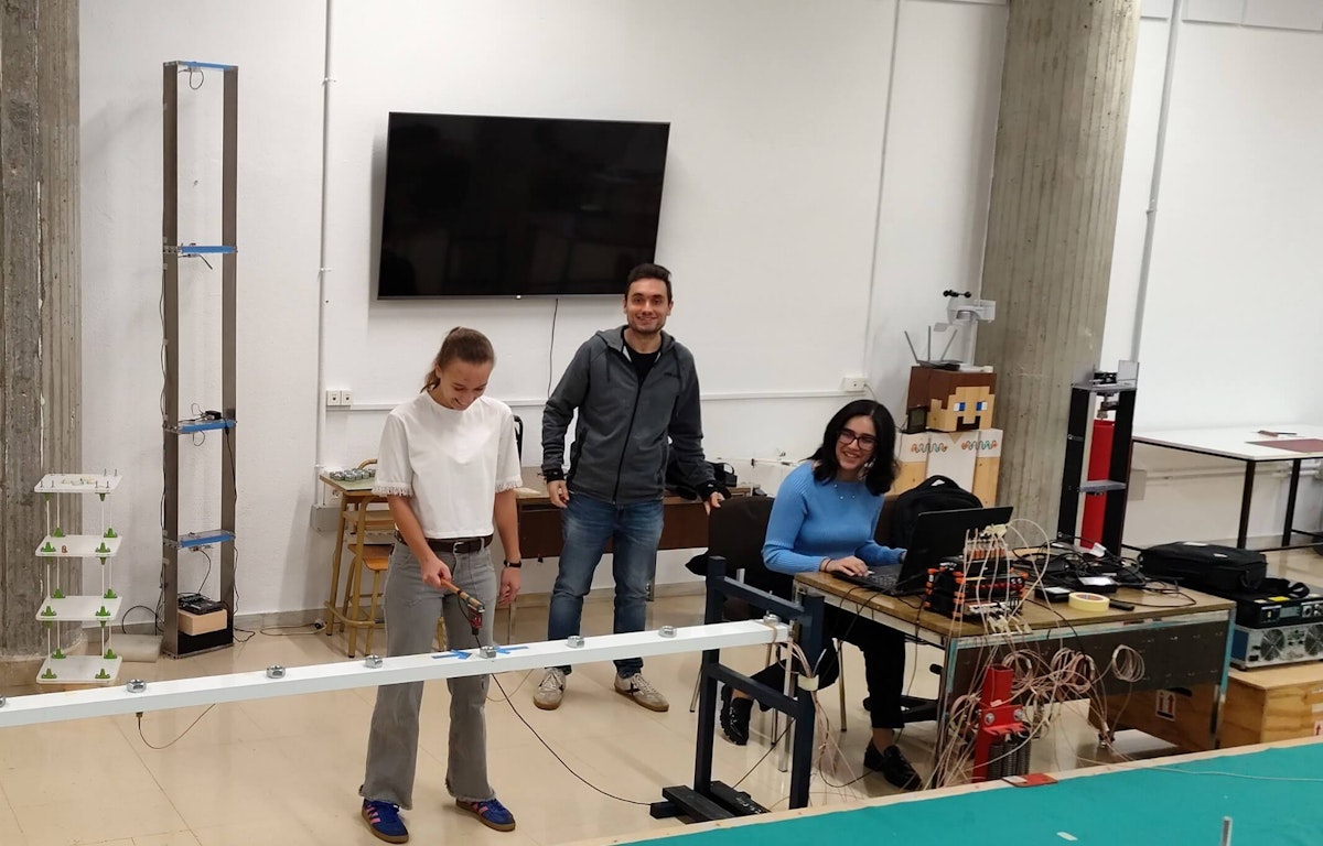
In a controlled laboratory setting, our university team set out to explore the dynamic behavior of a simply supported aluminum beam demonstrator using Experimental Modal Analysis (EMA). A simply supported beam is a beam that rests on two supports on its ends and is free to move vertically, with loads acting at specified points along its length. The aim was to understand how the beam vibrates under dynamic loads induced by an Impact Hammer.
Using sensors and specialized equipment driven by Dewesoft Dewe-43A DAQ and DewesoftX software, we measure and analyze the beam’s response. This response enables the identification of Natural Frequencies and Vibration Modes. Understanding these aspects is crucial for designing safer and more comfortable structures, simulating (modal
superposition) actions, failure detection, and Model Updating (FEM model calibration).
EMA with Dewesoft offers valuable insights for enhancing stability and performance in various real-world scenarios. This example highlights the importance of experimental techniques in advancing our understanding of structural dynamics at a fundamental level, thereby contributing to improved engineering practices.
EMA on slender structures
Understanding the dynamic behavior of slender structures is essential for ensuring their performance and safety under dynamic loads. Slender structures, characterized by one dimension that is significantly larger than the others, exhibit unique dynamic responses that need precise identification techniques. Our study focuses on investigating the dynamic response of a simply supported aluminum beam, which serves as a simplified demonstrator of this phenomenon.
Engineers use Experimental Modal Analysis (EMA) techniques to extract key parameters, such as natural frequencies and mode shapes, by measuring the dynamic response of the structure to the provided force excitation [1,2].
For our analysis, we deployed Dewesoft hardware and software, which enables precise data acquisition and frequency-domain processing [3]. A key focus is the Frequency Response Function (FRF), specifically the accelerance, which relates the acceleration response to input force in the frequency domain, according to this equation:
This complex function, expressed in magnitude and phase, characterizes the system’s dynamic behavior and response, like a classic Bode plot in control engineering. Natural frequencies are identified by magnitude (amplitude) peaks accompanied by phase shifts near 180° (π radians), providing insight into modal characteristics.
The objectives of this study are:
Understand the dynamic behavior of slender structures through experimental analysis.
Perform modal identification on a simply supported aluminum beam demonstrator;
Utilize Dewesoft equipment to acquire and analyze dynamic response data.
Performing EMA
The test object
Firstly, we provide a detailed description of the beam, experimental setup, instrumentation, and measurement procedures, along with supporting figures. It’s essential to know the details of the structure.
The aluminum (E = 70 GPa) beam is in a simply supported configuration. It has a length of L=6 m with a hollow rectangular section of 80 mm (width) and 40 mm (edge). The thickness is 2 mm, and the beam has a total mass of 5.15 kg, excluding extra nuts.
The extra nuts are then additional masses, each 0.190 kg, totaling 19 in number, spaced along its entire length, approximately 33.3 cm apart. Figure 1 gives an idea of the structure.


The measurement setup
The diagram in Figure 2 illustrates the points that define the beam’s geometry, ranging from point 1 to point 7 (red points), with point 1 located on one support and point 7 on the other, all equally spaced at a distance of 1 m.
Our testing of the structure through EMA started by instrumenting the beam with specific sensors and DAQ devices. We also needed a time-varying excitation force synced with dynamic response devices.
The experimental setup for excitation is an “Impact Hammer”, and we used an AEP transducers® TCA 10 kg load cell (2mV/V output) in a full Wheatstone bridge configuration with offset correction (see Figure 3). We consistently applied impacts at the beam´s point 2 (blue point), one meter from one support.
The response is measured at the red points using piezoelectric accelerometers arranged vertically. A total of seven MMF® KS76C.100 IEPE (sensitivity 100 mV/g) units (see Figure 4.d), one per point, are used (see Figure 4.c).
We attached the accelerometers to the beam by permanent magnets (see Figure 4.a), held in place by steel washers (see Figure 4.b) inside the aluminum hollow section. Magnetic sensor mounting is a widely used non-destructive technique, particularly when ferromagnetic materials are present, as seen with the inserted washers [3].


We used a Data Acquisition System (DAQ – datalogger), specifically a Dewesoft DEWE-43A EDU unit. It comprises eight analog input channels, and we connected the accelerometers and the load cell as shown in Figure 5. To implement the described methodology, we utilized DewesoftX software on the computer connected to the datalogger, along with the Modal Test license, which is part of the DEWE-43A EDU pack.
Additionally, we utilized Dewesoft DSI Adapters for universal amplifiers (TEDs, IEEE 1451.4) to connect the accelerometers to the system via the DSUB9 input ports, as illustrated in Figure 2. In the software, the analog-in palette configuration, depicted in Figure 6, sets the sampling rate (dynamic acquisition rate) at 400 Hz for recording time signals.


 and response (accelerometers – channels 1 to 7).")
List of hardware and software
One DEWE-43A DAQ - 8-channel USB data acquisition system, eight universal analog inputs, eight digital/counter/encoder inputs, and two high-speed CAN bus inputs.
DewesoftX - data acquisition and signal processing software.
Dewesoft Modal Test module – software for analysis of mechanical structures or electrical systems to determine the transfer characteristic (amplitude and phase) over a specific frequency range.
Seven Dewesoft DSI Adapters - IEPE signal adapters that turn analog input amplifiers into direct IEPE, charge, thermocouple, shunt, voltage, LVDT, or RTD input.
One AEP transducers® TCA 10 kg load cell (2mV/V output) - Load cell for the measurement of the excitation loads.
Seven MMF® KS76C.100 IEPE – IEPE axial accelerometer,100 mV/g sensitivity.
The measurements
Our testing protocol followed this procedure:
Our impacts at the beam’s point 2 never exceed 1g (approx. 10 N, 9.81 m/s2) to prevent excessive noise and vibration, as well as relative movement (bouncing) between the nuts and the beam.
We configured the Dewesoft Modal Test module for “Impact Hammer” testing. This setting contrasts a similar application note from the same laboratory, where an example of EMA with the aid of a shaker was conducted [4] on a much bigger timber platform. We used Exponential time windows to improve signal periodicity after each impact, detected through a trigger threshold (5 N) and an auxiliary pre-trigger (1%), which helped catch the real impact starting point. Since we set the frequency resolution at 0.01 Hz, each time window lasts 100 s.
We obtained a total of seven Accelerance FRFs (in Eq. 1 form), since the excitation point is always the same (point 2, see Figure 2) and seven response points are available. In particular, the FRF that relates the response to the force excitation at the same point is called Driving Point Accelerance (DPA), a common denomination in vibration measurements and modal analysis.
We obtained the FRFs in the frequency domain after averaging the four Time windows from the data registered by both the sensors and the datalogger. Subsequently, we performed vibration analysis in the range of [0,30] Hz.
The main results
Before presenting the main results and conclusions regarding the tested laboratory demonstrator (see Figure 1), we must briefly explain several concepts in addition to the main goals and methodology: Natural Frequencies and Vibration Modes. Damping ratios are another key aspect of modal identification; however, given the introductory nature of this text, we don’t address this in the results.
Natural Frequencies (f). They refer to the specific frequencies at which a structure tends to vibrate when subjected to disturbance. These frequencies are intrinsic to the structure’s physical properties, such as its mass, stiffness, geometry, and boundary conditions. When a structure is excited at one of its Natural Frequencies, resonance occurs, leading to significant amplitude vibrations.
Vibration Modes (mode shapes). They describe the specific patterns of displacement a structure undergoes when vibrating at each Natural Frequency. Each mode corresponds to a unique frequency and represents a distinct way in which the structure can vibrate. These modes are fundamental in understanding how structures respond to dynamic loads.
Figure 7 depicts the beam’s first three vibration modes identified after performing the EMA.
However, video animations of these mode shapes provide a more accurate virtual representation of vibration at Natural Frequencies. The animations visualize the different ways the beam can vibrate at the frequencies mentioned above.
The number of half-sine waves that fit within the beam’s length characterizes these modes. The first mode occurs at 2.96 Hz, and it’s the simplest one, characterized by a single half-sine wave. The second mode, at 11.69 Hz, introduces a central node (point 4 in Figure 2), where no vertical displacement occurs. Finally, the third mode, observed at 25.86 Hz, features two such nodes (points 3 and 5), creating three distinct segments that vibrate in alternating directions.
Since displacements are small, a more generic video of the vibrating structure during the EMA procedure (response after impacts and time windows averaging) would not have provided the desired displacement view, so the representation available in DewesoftX is of great interest.
We obtained the seven FRFs by averaging the input signals from the sensors over time windows initiated by the trigger generated from the impact at the beam’s point 2. We performed these calculations because the FRF is a complex function that expresses both magnitude and phase.
Figure 8 displays the DewesoftX Modal Test Module results, which include various widgets, such as 2D Graphs for FRF representation and coherence, as well as force-time recorders and an indicator lamp for data storage.
Specifically, the coherence function measures the linear dependence between the input (excitation) and output (response) signals at each frequency point, ranging from 0 to 1. Since an FRF is of a linear nature, the coherence function should be close to 1.

![Vibration Modes representation within the analyzed frequency range ([0-30] Hz). Click to watch animations.](https://www.datocms-assets.com/53444/1762353418-vibration-modes-representation.png?auto=format&dpr=1.5&fit=max&w=1024 "Vibration Modes representation within the analyzed frequency range ([0-30] Hz). Click to watch animations.")


Finally, we exported the FRFs using the software tools to a Microsoft Excel spreadsheet, and Figure 9 provides a more precise representation of their magnitude (Y-axis on a logarithmic scale, m/s2/N).
Examining the magnitude plots, we identified natural frequencies by the peaks in the signals. It is imperative to note that, while the FRFs at the supports are theoretically zero since a support does not have a motion in the measured vertical direction, in practice, noisy, close to but non-zero functions are obtained (points 1 and 7).
On the other hand, phase and coherence plots depicted in Figure 8 indicate the 180° (π radians) shifts corresponding to a vibration mode (peak) at a particular natural frequency, and a perfect linear dependence between the averaged signals, respectively.
We could also consider other interesting interpretations based on the calculated FRFs, which depend on the number of peaks in each function. For example, FRF 42 only presents two peaks instead of three, since point 4 is a node in the second identified mode of vibration (see Figure 2).
That means, no amplified response in terms of acceleration or displacement occurs at that point when we apply a load in point 2 at the natural frequency, f2=11.69 Hz (see Figure 7.b). The same also applies to FRFs 32 and 52, where the peak at f3=25.86 Hz is missing, meaning response points 3 and 5 correspond to nodes, as seen in the mode shape of Figure 7.c.
Additionally, the small, non-ideal motions at the supports (points 1 and 7) result in functions with peaks of lower magnitude. We consistently made an impact at point 2 and never found that particular point to be a node in the Vibration Modes within the analyzed frequency range. That is visible in FRF 22 (DPA).


Conclusions
Our study successfully demonstrated the benefits of using Experimental Modal Analysis (EMA) to evaluate the dynamic behavior of a simply supported aluminum beam in a controlled laboratory setting. Using Dewesoft Dewe-43A DAQ and DewesoftX software, we have identified the beam’s natural frequencies and Vibration Modes, providing critical insights into its dynamic response.
Our work underscores the importance of precise instrumentation and advanced experimental tools in structural dynamics. Furthermore, the successful application of EMA techniques in this laboratory setting indicates its potential for broader implementation in real-world scenarios, along with Damping Ratio identification, a prevalent task among practitioners.
As an aspect for improvement, it is convenient to report the appearance of small lobes in the FRF magnitudes (see Figures 8 and 9), which are indicative of the impacts not applied under conditions of complete rest. This effect does not compromise our primary objectives nor the accurate identification of natural frequencies and vibration modes within the considered frequency range. However, it highlights the need for careful impact control in future experiments to enhance data quality.
References
“What is Modal Analysis?”, Dewesoft, May 2023. [Online]. [Accessed: July 14, 2025].
Avitabile, P. "Experimental modal analysis - A simple non-mathematical presentation," S V, vol. 35, pp. 20-31, 2001.
Sujatha, C. “Basics of Experimental Modal Analysis”, in: “Vibration, Acoustics and Strain Measurement”, Springer Charm, 2023.
Fernández, G. and Lorenzana, A. “Experimental Modal Analysis of a Pedestrian Platform”, Dewesoft, May 2025. [Online]. [Accessed: July 31, 2025]