Table of contents
Browse categories
Browse authors
 AL
ALAlessia Longo
 AH
AHAl Hoge
 AB
ABAljaž Blažun
 BJ
BJBernard Jerman
 BČ
BČBojan Čontala
 CF
CFCarsten Frederiksen
 CS
CSCarsten Stjernfelt
 DC
DCDaniel Colmenares
 DF
DFDino Florjančič
 EB
EBEmanuele Burgognoni
 EK
EKEva Kalšek
 FB
FBFranck Beranger
 GR
GRGabriele Ribichini
Glacier Chen
 GS
GSGrant Maloy Smith
 HB
HBHelmut Behmüller
 IB
IBIza Burnik
 JO
JOJaka Ogorevc
 JR
JRJake Rosenthal
 JS
JSJernej Sirk
 JM
JMJohn Miller
 KM
KMKarla Yera Morales
 KD
KDKayla Day
 KS
KSKonrad Schweiger
Leslie Wang
 LS
LSLoïc Siret
 LJ
LJLuka Jerman
 MB
MBMarco Behmer
 MR
MRMarco Ribichini
 ML
MLMatic Lebar
 MS
MSMatjaž Strniša
 ME
MEMatthew Engquist
 ME
MEMichael Elmerick
 NP
NPNicolas Phan
 OM
OMOwen Maginity
 PF
PFPatrick Fu
 PR
PRPrimož Rome
 RM
RMRok Mesar
 RS
RSRupert Schwarz
 SA
SASamuele Ardizio
 SK
SKSimon Kodrič
 SG
SGSøren Linnet Gjelstrup
 TH
THThorsten Hartleb
 TV
TVTirin Varghese
 UK
UKUrban Kuhar
Valentino Pagliara
 VS
VSVid Selič
 WK
WKWill Kooiker
Reducing Emissions with Solar and Borehole Thermal Energy Storage (BTES)

Aljaž Blažun && Gregor Kisel, Aleš Vozelj
November 5, 2025
Dewesoft Inspiretech has developed and implemented a Borehole Thermal Energy Storage (BTES) system at a Dewesoft industrial facility in Trbovlje, Slovenia. The system is integrated with a smart monitoring setup to reduce carbon emissions, lower operational costs, and maximize energy independence. Dewesoft Inspiretech developed and implemented a Borehole Thermal Energy Storage (BTES) system at a Dewesoft industrial facility in Trbovlje, Slovenia. The system integrates smart monitoring to cut carbon emissions, lower operational costs, and increase energy independence.

Heating and cooling account for 37% of energy-related emissions in Europe. With seasonal energy availability mismatched to seasonal heating demands—particularly in solar energy—the challenge is to store excess summer heat for use in winter. BTES, a subset of Underground Thermal Energy Storage (UTES), offers a solution by storing thermal energy in underground boreholes.
Engineers have already been successfully implementing this relatively new technology worldwide. A BTES system comprises a field of vertical geothermal boreholes that serve as a seasonal thermal energy storage solution. During summer, solar collectors and heat pumps supply the system with excess thermal energy. This stored energy is retrieved during winter when demand is higher.
The concept and the building
Our BTES energy system, designed and developed by Dewesoft Inspiretech in collaboration with Dewesoft, is intended to heat and cool one of our industrial facilities in Trbovlje.
Dewesoft acquired the 2,800 m² facility in 2021 and has since undergone a comprehensive reconstruction of the building, including the renewal of the support structure, walls, and roof. Today, it houses the Dewesoft CNC workshop, L-Tek production facilities, a warehouse, and several startup companies.
The idea behind the system is:
Create a system that requires no energy other than solar energy for its operation.
Does not burden the electrical grid.
Generates no emissions.
Contributes to no global warming.
The goal of Dewesoft Inspiretech’s project was to:
Achieve energy self-sufficiency through integration with on-site solar energy,
Store thermal energy efficiently and sustainably,
Monitor and analyze BTES performance over time,
Establish a real-world validation for BTES in a mid-European climate,
Set a replicable model for other industries.
We evaluated and dimensioned the BTES thermal storage unit design through both analytical and numerical simulations. This multi-layered research approach enabled the precise validation of all key system parameters, ensuring optimal efficiency under the given operational conditions.


Solar panels and heat pumps
The most interesting thing is that the energy stored in the UTES geo probe is practically free. Conventional heat pumps operate on the air-to-water principle, so when cooling rooms in the summer, they heat the outside air. The conceptual solution uses a ground/water heat pump, where on one side, we cool the room, and on the other side, we overheat the UTES geo probe.
The sun is a source of energy. It does not shine at night; in winter, it shines five times less than in summer. Therefore, we designed the heat pump system to operate only when the sun is shining.
The building features 400 m² of solar panels, supplying two heat pumps of 100 kW each. These panels generate all the power required to operate the pumps, which means we nearly achieve complete energy independence from the electrical grid.
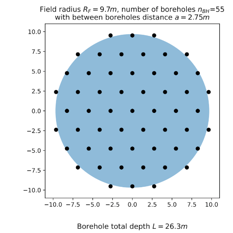
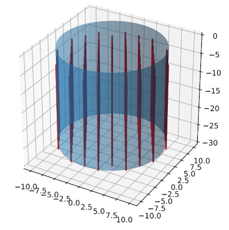
Figures 5 and 6 illustrate the principle of boreholes that enable seasonal heat storage.
Heat generated during building cooling in summer—usually wasted—is instead redirected into the BTES field using solar-powered heat pumps. In winter, the stored heat is utilized for underfloor heating, thereby reducing reliance on fossil fuels.
At a sufficiently high field temperature, we heat the rooms in winter only by using a circulation pump.
The thermal storage and heating design
Facility: 2800 m² production area
Solar panels: 400 m²
Heat pumps: 2 × 100 kW (thermal)
BTES configuration: 55 boreholes, each 27 m deep
Piping: Total length 1500 m
Target temperature range: 55 °C (start of winter) to 30 °C (end of winter)
Charging energy input (summer): 160 MWh
Retrievable energy (winter): 80 MWh
Efficiency: Estimated 40–50%
Payback period: 5–7 years
The BTES system can also store energy from technological sources, such as industrial equipment and furnaces, during the summer, allowing for the complete charging of the BTES system for winter. From this stored energy, we retrieve approximately half of the thermal energy that was input during the summer months.
Our BTES system operates based on the fundamental principle of two operating modes: the first is the charging phase, and the second is the discharging phase. Both names are related to the current status of the BTES storage. The charging phase typically occurs between mid-April and mid-October, while the discharging phase characterizes the remainder of the year.
During the charging phase, we store heat. To have sufficient output energy during the heating season, we actually store more than we need, as we lose some energy, primarily through conduction in the soil. The energy we want to store is freely available when charging from solar collectors, PV, and surplus energy from air conditioners.
During the charging season, electricity from photovoltaics powers a water-to-water heat pump, which extracts heat from the building (for cooling) and transfers the surplus heat to the storage. When the temperature in the building is appropriate during the charging season, there is no need for the water/water heat pump to operate. Then the air/water pump comes into use, extracting heat from the ambient air outside the building and raising its energy to an even higher level, storing this energy in BTU storage.
A third energy source is technological surplus heat, primarily generated by SMD pick-and-place machines. This energy is transferred directly to the storage. The third source of energy is also available during the discharging season and used in place.
The monitoring system
Instrumentation and setup
To ensure long-term performance and real-time diagnostics, Dewesoft implemented a multi-tier monitoring architecture:
Devices:
Two Dewesoft IOLITEi-8xRTD for precision temperature monitoring
Industrial DIN-rail-mounted PC as the acquisition hub
Sensors:
Twelve 4-wire PT100 temperature sensors (IP67-rated) installed at two vertical levels: 1/3 and 2/3 depth. Locations: North, South, East, West, and two central points per level
Software:
DewesoftX - data acquisition and digital signal processing software, for acquisition and configuration.
Historian plugin - a database software service for long-term and permanent monitoring, for logging and automatic data transmission every 30 seconds.
Grafana - a multi-platform open-source analytics and interactive visualization web application for long-term visualization and trend analytics.
FUXA - a web-based process visualization (SCADA/HMI/Dashboard) software, functions as a real-time operational dashboard.
Visualization tools
We applied Grafana to track thermal behavior and efficiency across seasons. The software allows engineers and management to observe changes in thermal gradients, long-term heat retention, and recovery trends. FUXA enabled us to provide real-time visualization of system temperatures and current operational status, supporting field maintenance and active control monitoring.
Monitoring integration and control
To control the storage, we measure soil temperatures at various points. For control, we use the core temperature, which is the average between temperatures measured at 10.5 m and 18 m deep at the center of the storage.
We then compare this core temperature with a theoretically calculated characteristic temperature that our storage should be at a specific time of the year. Based on the differences between those two temperatures, the control system then decides what to do.
While we have fully integrated temperature monitoring and storage visualization through Dewesoft systems, additional metrics, such as power consumption and broader control logic (e.g., flow rate, pressure, solar output), are handled by third-party systems.
These data streams merge into Grafana through Node-RED, a low-code programming platform for applications to collect, transform, and visualize data, ensuring a unified dashboard experience that does not interfere with core DewesoftX functionality.
Results - status
We control the BTES via monitoring its core temperature. In Figure 11, the curve labeled “2025 by theoretical model” illustrates the core temperatures we anticipate being able to produce throughout the year, corresponding to 80 MWh of energy.
The green curve, labeled "Monitored temperature", represents the current core temperature. The other three curves are cubic polynomial approximations of where we want to be at a specific time of the year (where +1/-1°C curves present some tolerance of expectations).
Currently, we are slightly below the target temperature, approximately 0.5 °C below, but this is acceptable for the first complete year of using the BTES system.
Impact and benefits
Environmental Impact:
Substantial reduction in greenhouse gas emissions
Elimination of waste heat losses
Lower reliance on fossil fuels
Economic Impact:
17% reduction in operational costs
Payback through energy savings within 5–7 years
Energy Independence:
Near full autonomy from the electrical grid in heating/cooling
Optimized use of renewable energy via solar integration
Performance Visibility:
High-resolution temporal and spatial monitoring of subsurface temperatures
Enables fine-tuning of seasonal performance and predictive maintenance
Conclusion
The BTES system and monitoring architecture developed by Dewesoft Inspiretech and Dewesoft show how innovative engineering, real-time data, and renewable energy can work together to create efficient, clean, and cost-effective energy solutions.
The system provides substantial operational cost savings, reduces dependence on fossil fuels, and enhances the stability and reliability of the electrical grid.
The fusion of Dewesoft's precision measurement tools with Grafana's visualization and FUXA’s real-time control creates a scalable template for industries worldwide seeking sustainable energy strategies.
This project is not only a step toward greener operations—it’s a demonstration of leadership in deploying advanced thermal storage technologies backed by data intelligence.