Table of contents
Browse categories
Browse authors
 AL
ALAlessia Longo
 AH
AHAl Hoge
 AB
ABAljaž Blažun
 BJ
BJBernard Jerman
 BČ
BČBojan Čontala
 CF
CFCarsten Frederiksen
 CS
CSCarsten Stjernfelt
 DC
DCDaniel Colmenares
 DF
DFDino Florjančič
 EB
EBEmanuele Burgognoni
 EK
EKEva Kalšek
 FB
FBFranck Beranger
 GR
GRGabriele Ribichini
Glacier Chen
 GS
GSGrant Maloy Smith
 HB
HBHelmut Behmüller
 IB
IBIza Burnik
 JO
JOJaka Ogorevc
 JR
JRJake Rosenthal
 JS
JSJernej Sirk
 JM
JMJohn Miller
 KM
KMKarla Yera Morales
 KD
KDKayla Day
 KS
KSKonrad Schweiger
Leslie Wang
 LS
LSLoïc Siret
 LJ
LJLuka Jerman
 MB
MBMarco Behmer
 MR
MRMarco Ribichini
 ML
MLMatic Lebar
 MS
MSMatjaž Strniša
 ME
MEMatthew Engquist
 ME
MEMichael Elmerick
 NP
NPNicolas Phan
 OM
OMOwen Maginity
 PF
PFPatrick Fu
 PR
PRPrimož Rome
 RM
RMRok Mesar
 RS
RSRupert Schwarz
 SA
SASamuele Ardizio
 SK
SKSimon Kodrič
 SG
SGSøren Linnet Gjelstrup
 TH
THThorsten Hartleb
 TV
TVTirin Varghese
 UK
UKUrban Kuhar
Valentino Pagliara
 VS
VSVid Selič
 WK
WKWill Kooiker
Propellant Development and Data Acquisition in Rocket Motor Static Firing Test
Teresa Sánchez Sarria and Miguel Tejera Lesmes
University of Sevilla
November 13, 2025
The NAOS EVO rocket motor successfully underwent its first static firing employing a sorbitol-based solid propellant. This test marked the initial validation of a new propellant formulation within the Coheteros propulsion program. We used the Dewesoft SIRIUSi-XHS-8xACC system for high-precision data acquisition. Results confirmed the reliability of the motor design and highlighted areas for refinement in propellant grain manufacturing and combustion stability.
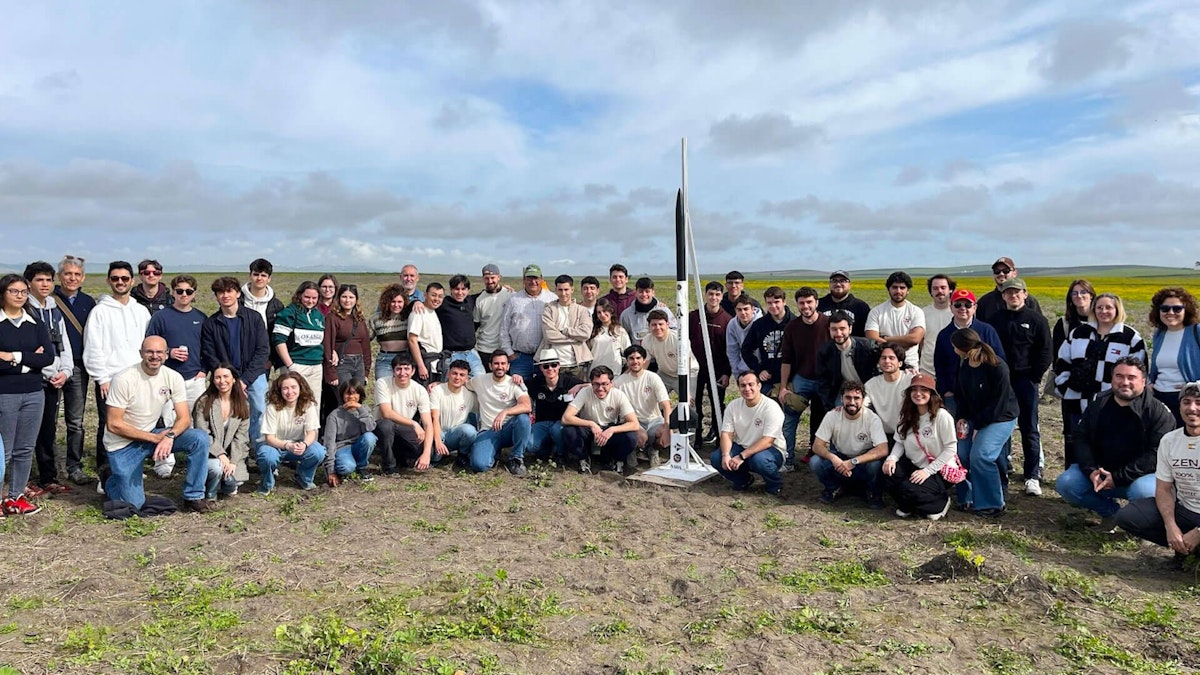
The Coheteros, in English, The Rocketeers, is a student association affiliated with ETSI, the Higher Technical School of Engineering at the University of Sevilla in Spain. At Coheteros, we design, develop, manufacture, and launch prototypes of experimental space pitchers, leveraging our more than two years of experience in the sector. We are also part of the Seville Space Forum, a group comprising public, private entities, and associations that aim to foster a passion for space.
The successful preparation and execution of a static test of the NAOS EVO rocket motor represents a key milestone in our association’s development. The test will significantly contribute to the improvement of our propulsion systems for future solid-propellant launch vehicles.
We will describe the complete process carried out, including the materials and methods used in the manufacturing of the propellant grains, as well as the preparation of the combustion chamber and the pressure sensor employed.
For the first time, we integrated this sensor with the Dewesoft SIRIUSi data acquisition system, a highly efficient and capable device known for its high-precision data collection and advanced analysis capabilities. This system will enable more advanced analysis of the test results, providing us with valuable insights for future improvements.
The following video presents the complete static fire test corresponding to the results we present here. It provides a real-time visual record of the motor’s ignition, combustion phase, and shutdown, complementing the quantitative data with direct observational evidence.
Materials and methods
Rocket engine
The combustion chamber, nozzle, and rear closure each require two O-rings for a tight seal.
Dimensions:
Outer diameter of chamber: 63.5 mm
Nozzle throat diameter: 19 mm
Nozzle inlet diameter: 47.96 mm
Nozzle outlet diameter: 41.67 mm
Chamber length: 550 mm
Nozzle convergence angle: 41°
Nozzle divergent angle: 12°
Pressure and Temperature:
Nominal operating pressure: 6 MPa
Maximum operating pressure: 10 MPa
Internal chamber temperature: 1625 °K
Materials:
Nozzle and closure: A304 stainless steel
Combustion chamber: Standard commercial A304 stainless steel tube


Propellant
This section describes the fundamental properties of the solid propellant used in the rocket motor design: KN-Sorbitol (Potassium Nitrate/Sorbitol) in a 65/35 mass ratio (Oxidizer/Fuel).
We selected sorbitol as the fuel component in our 65/35 KN-Sorbitol formulation after careful consideration and thorough research. We prioritized safety and ease of manufacturing over other sugar-based fuels previously investigated, such as sucrose and dextrose, demonstrating our team's expertise in propellant selection.
Initially, we evaluated Dextrose. While it is more manageable than some other sugars, it exhibited a moderate burn rate that, under certain conditions, could result in elevated chamber pressures. These pressures raised concerns about the structural integrity of the motor and implied the need for a more robust and consequently heavier design.
We also considered Sucrose. However, it presented significant processing challenges due to its tendency to caramelize rapidly at relatively low temperatures. This behavior made the mixing and casting processes difficult to control and also introduced unpredictability in their combustion characteristics. For these reasons, we ultimately discarded sucrose.
Eventually, we selected Sorbitol as the preferred fuel due to several advantages: it is easier to process, as it does not caramelize as readily (in contrast to sucrose and dextrose), allowing for safer cooking with a longer working time; and we expect it to deliver a slower and more consistent burn rate, helping to avoid excessive pressure spikes in the combustion chamber and resulting in a higher total impulse.
Table 1 shows the physical and thermochemical properties of the KNSB-65/35 formulation. This information is based on published research by Richard Nakka, which we supplemented with data obtained from our own experimental testing of the propellant.
Propellant KNSB-65/35
| / | Symbol | Unit | Result |
|---|---|---|---|
| Ideal grain mass density | ρ | gcm3 | 1,879 |
| Specific heat ratio, two phases | k | - | 1,042 |
| Specific heat ratio, mixture | k | - | 1,137 |
| Effective molecular weight | M | kgkmol | 39,9 |
| Chamber temperature | T0 | K | 1600 |
In addition to these fundamental properties, the propellant's burn rate is a critical factor directly related to the motor's dynamic performance. The following subsection details the burn behavior and the methodology used for its characterization.
Burn rate and Saint Robert’s law
The burn rate (r) is a fundamental property of solid propellants, defining the speed at which the propellant surface recedes during combustion, producing gas. This parameter is directly proportional to the mass flow rate of combustion gases, and therefore to the thrust that the rocket motor can generate.
Engineers commonly describe the relationship between burn rate and chamber pressure by Saint Robert’s Law, also known as the power law or Vieille’s Law:
Where:
r is the burn rate of the propellant
P is the absolute pressure in the combustion chamber
a is the burn rate coefficient
n is the pressure exponent (or burn rate exponent)
The values of a and n are specific to each propellant formulation and must be determined experimentally. For the 65/35 KN-Sorbitol propellant, these parameters are not constant across the entire operating pressure range; instead, they vary depending on the pressure regime. This variation is due to changes in the propellant's combustion mechanisms under different pressure conditions.
The table below summarizes the experimentally determined values of a and n for the propellant studied:
Burn rate of KN-Sorbitol 65/35 O/F propellant
| Pressure range | a | n |
|---|---|---|
| Pressure, MPa | MPa, mm/second | - |
| 0,101 to 0.807 | 10,708 | 0,625 |
| 0.807 to 1,503 | 8,763 | -0,314 |
| 1,503 to 3,792 | 7,852 | -0,013 |
| 3,792 to 7,033 | 3,907 | 0,535 |
| 7,033 to 10,67 | 9,653 | 0,064 |
Grain curing process
The fabrication of the KNSB-65/35 propellant begins with powder preparation: We weighed Potassium Nitrate (KN) and Sorbitol (SB) according to the desired 65/35 mass ratio. The KN is finely ground (approximately 15 seconds per two tablespoons). At the same time, the SB is used in its original granulated form, following Richard Nakka’s recommendations to control the viscosity of the molten mixture better. Both components are dry-mixed for a minimum of 3 hours to ensure a uniform composition.
The experimental cooking process begins by heating half of the dry mixture to 125 °C. The temperature is then increased to 130 °C for 3–4 minutes to accelerate the melting process, and subsequently lowered back to 125 °C once melting begins (after approximately 5–6 minutes). Once the first half has fully melted, we add the remaining dry mixture, completing the fusion process in about 12 minutes.
Compared to Nakka’s baseline procedure (110 °C for 10 minutes), our process involved slightly higher temperatures (125–130 °C). However, no visible degradation, such as discoloration or scorching, was observed, suggesting effective thermal control throughout the curing process.
In conclusion, the grain curing process was successful, resulting in the complete fusion of the KNSB mixture without any apparent degradation. Although the processing temperatures slightly exceeded those proposed by Nakka, we detected no immediate adverse effects.


Molding and grain solidification
One of the main challenges encountered during the production process was the demolding of the solidified propellant. This step involves removing the core from the grain without deforming or damaging it, while maintaining its structural integrity, particularly by avoiding cracks that could negatively impact combustion performance.
Several tests were conducted during development to optimize this process. Initial strategies included the use of mold release agents, such as greases, applied to the core to ease extraction after solidification. Although this method reduced friction to some extent, it presented significant drawbacks: residue left on the grain surface, lack of uniformity, and potential interference with ignition or combustion.
In parallel, we evaluated different materials for the cores to assess their demolding performance. We tested cores made of aluminum, stainless steel, and Teflon (PTFE).
Among these, Teflon showed the best results in terms of clean and adhesion-free demolding. We attribute this performance to its low coefficient of friction and minimal surface energy, which reduces adhesion between the propellant and the mold. In contrast, both aluminum and stainless steel exhibited higher adhesion and required greater extraction force, increasing the risk of grain fracture.
In addition to material selection, we investigated the effect of introducing a slight taper in the core. The rationale behind this geometric modification is to reduce the tangential friction forces generated between the grain and the core walls during extraction. Theoretically, incorporating a draft angle converts part of the axial extraction force into a radial component, facilitating slippage.
We optimized this draft angle based on geometric and tribological criteria. Literature suggests that angles between 1° and 3° are effective for precision cylindrical molds. After several iterations, we experimentally determined that an angle of approximately 2° offered the best balance between ease of extraction and dimensional stability of the grain, while maintaining a suitable geometry for internal-burning configurations.
As a result of this research, the final procedure adopted by our team consists of:
Using machined Teflon cores with an internal taper of 2° relative to the longitudinal axis.
Applying uniform, gentle axial pressure during demolding, without the use of lubricants or chemical agents, thereby avoiding surface contamination of the grain.
Allowing for controlled cooling of the propellant before demolding to prevent internal stresses or shrinkage-induced cracking.
This optimized procedure has not only improved demolding efficiency but also significantly reduced the failure rate due to grain fracture, increasing grain lifespan and improving the repeatability of the manufacturing process.


Pressure measurement system
To characterize the performance of the rocket motor during static testing, we implemented a robust system to measure the pressure inside the combustion chamber. This system combined both analog and digital instrumentation to ensure accurate and reliable data acquisition.
We conducted the primary pressure measurement using an analog dial gauge connected directly to the combustion chamber of the rocket motor. This instrument provided real-time visual readings of chamber pressure during the test, enabling immediate assessment of motor behavior.
In parallel, we integrated a TE Connectivity M320D pressure sensor with the system for digital data acquisition. This pressure transducer connects to a signal conditioning circuit, designed to adapt the sensor’s output to meet the input requirements of the data acquisition system. The conditioned signal was then routed to the central data logging unit, enabling real-time monitoring and continuous recording of chamber pressure throughout the test.


Dewesoft SIRIUSi Device
Regarding the data acquisition system, we used a SIRIUSi-XHS-8xACC, utilizing one of its six available channels to connect the pressure sensor and record the corresponding measurements. This system comes with DewesoftX data acquisition and signal processing software.
We reduced the data acquisition rate from 20,000 Hz to 1,000 Hz, which significantly lowered the volume of exported data and facilitated post-processing and analysis.
We configured multiple output displays, including two recorders with the following settings:
The first recorder displayed the raw measured signal, with an auto-scaling y-axis showing pressure in bars.
The second displayed a smoothed, averaged signal, providing a more precise representation by reducing noise in the visual output.
Additionally, we added an analog-style dial gauge display, emulating the physical gauge used at the test site and connected to the same pressure sensor. This addition proved particularly useful in video recordings, as it clearly showed the pressure being reached in real-time. In contrast, the digital sensor had a measurement limit of 50 bar, which restricted its ability to represent the pressure evolution once it exceeded that threshold.
Ignitor description and operation
The ignitor used consists of a resistive wire coated with a small amount of black powder and insulated with protective paper. We connected this resistive element via two long cables to an external battery, which serves a dual purpose. When we press the red button, it powers the resistive wire at the desired ignition moment. Also, it supplies continuous power to the pressure sensor.
When the portable battery is activated, and we press the red button, an electrical short circuit occurs across the resistive wire, generating a small spark. This spark ignites the black powder coating, producing a minor explosion that initiates combustion in the propellant grains.
The ignitor is positioned at the rear end of the combustion chamber, inserted through the nozzle, the only accessible point. It is placed as close as possible to the chamber closure so that the grain farthest from the nozzle ignites first.
This arrangement causes the combustion gases to travel along the chamber rather than exiting directly through the nozzle, promoting progressive ignition of the remaining grains instead of simultaneous ignition, which would be preferable but is not achievable with the current setup.
For safety reasons, a person stationed at a safe distance from the test area operates the ignition button manually.
Sensor calibration procedure
Before ignition, we performed a pressure sensor calibration procedure to verify that the system accurately received and recorded pressure data. The calibration setup involved powering the pressure sensor using an external power supply, following the wiring scheme shown in the system circuit diagram. Simultaneously, we connected the signal cable to the Dewesoft SIRIUSi acquisition unit.
The following figures illustrate the setup implemented for this test within the Dewesoft software environment.


We configured two mathematical channels, each represented by a digital gauge, to display the maximum pressure value and the corresponding time at which it occurs since data recording began. Figure 9 shows the configuration applied.


The sensor’s pressure intake, inserted through the combustion chamber closure, was connected to a manual pressure calibration device, which allowed the application of controlled pressure in bar increments.
The main goal of the calibration was to confirm that the recorded data was consistent and coherent with the actual pressure applied, as indicated by the reference device. We used multiple controlled pressure levels to test the system:


.")
For each pressure level, we recorded both the raw signal value and the corresponding smoothed average value. This dual measurement approach allowed for immediate detection of any potential anomalies or signal instability. In all cases, we found the readings to be highly consistent with the applied pressure, and the averaged values closely matched the actual input, confirming proper sensor behavior and system integrity.
We observed minor pressure drops during each step due to internal losses within the calibration setup. Both the analog gauge integrated into the pressure sensor and the data acquisition system reflected these drops simultaneously.
Below is an image showing the complete calibration setup, with all components properly connected and the system ready for testing:


Test objective
The primary objective of this test was to initiate the study of a new sorbitol-based solid propellant intended for use in the NAOS EVO rocket, a future launch vehicle developed by the Coheteros Association. In parallel, the test also aimed to commission and validate the recently acquired Dewesoft SIRIUSi data acquisition system. This task posed a significant challenge, as the team had no prior experience operating such equipment.
Given the novelty of the sorbitol propellant, the test involved considerable complexity throughout the entire process, from the careful formulation and manufacturing of the propellant grains to the ignition phase, where we ultimately assessed the effectiveness of the preparation.
Before the static firing, we conducted a series of simulations using HERMES, the association’s in-house developed motor performance simulator. These simulations were crucial for ensuring the safety and feasibility of the test. They enabled control over key parameters such as expected chamber pressure and thrust levels, while also helping determine the optimal grain configuration for stable and predictable performance.


The simulations predicted the following key performance metrics:
Combustion duration and thrust time profile
Peak chamber pressure
Total impulse
Simulated chamber pressure (Graph 2A)


The simulation predicts a maximum chamber pressure of approximately 7 MPa, sustained for nearly 0.6 seconds before gradually declining. The pressure drops significantly after the 1-second mark and returns to atmospheric levels by about 1.5 seconds. This pressure curve suggests a stable burn phase followed by a controlled tail-off, which aligns with expectations for this propellant formulation.
Simulated thrust profile


The thrust simulation shows a peak thrust of approximately 125 kg, reached shortly after ignition and maintained for about 0.5 seconds. The thrust then begins to decline in a smooth, continuous manner, reaching near zero by 1.5 seconds. The simulation includes a comparison with a reference curve (Richard Nakka), showing close agreement in terms of peak thrust and burn duration. This accordance indicates that the designed grain configuration and propellant behavior closely match established performance benchmarks.
These simulations provided essential insight for setting safe operational limits and defining expectations, significantly contributing to a controlled and successful test campaign.
Results and discussion
Chamber pressure – real vs. simulated


The graph shown in Figure 16 presents the real-time chamber pressure data captured by the pressure sensor during the NAOS EVO motor static firing test.
Compared to the simulated pressure profile, which predicted a peak pressure of approximately 7 MPa sustained for 0.6 seconds, the real data exhibits the following key characteristics:
Initial pressurization begins approximately 0.45 seconds after launch, with a steep and continuous rise in pressure.
A first plateau is observed at around 6.1 MPa between 0.9 s and 1.1 s, followed by a secondary pressure rise peaking near 7.2 MPa at approximately 1.35 s, which slightly exceeds the predicted maximum.
After the peak, pressure drops rapidly, with a steep descent lasting until approximately 1.7 seconds, followed by a more gradual tail-off toward ambient conditions.
Some irregularities and oscillations are noticeable in the peak region, possibly due to combustion instabilities or transient effects during grain regression and nozzle flow.
These deviations from the simulated profile, especially the dual pressure peak, could be attributed to:
Slight variations in grain geometry or combustion surface evolution.
Local differences in burn rate due to uneven sorbitol distribution or voids.
Measurement noise or signal reflections, although the calibration process previously confirmed the sensor's accuracy.
Despite these variations, the overall shape and duration of the combustion phase closely match the simulation, confirming the validity of the model used in HERMES. The results also indicate a successful ignition and stable motor operation, reaching the design pressure safely.
Thrust – real vs. simulated
The thrust data was collected using a load cell connected to an independent data acquisition system, separate from the Dewesoft SIRIUSi. While useful for a general estimation of motor performance, this system lacks the precision and resolution of the primary pressure acquisition setup. It is therefore considered of secondary importance for this study.


Post-test inspection
We conducted a thorough post-test inspection to evaluate the condition of the combustion chamber assembly, including the closure system and nozzle. The following images document the state of the components after the firing.
The results show that both the chamber and its structural components remain in excellent condition and are fully reusable for future test campaigns. We observed no significant damage or deformation.
The only noticeable alteration occurred in the nozzle throat. There, we detected a slight reduction in diameter (on the order of millimeters). We attributed this erosion to material ablation caused by exposure to extremely high temperatures, estimated to have reached approximately 1600 K during peak combustion.
Moreover, the rubber sealing rings (black bands) are intact and undamaged, maintaining their elasticity and sealing function. At the same time, the internal wooden spacer block, used to reduce chamber volume, retained its original dimensions and showed no signs of deformation or charring.
Overall, the chamber demonstrated robust structural integrity and thermal resilience, and we expect it to withstand multiple future firings without requiring major refurbishment.


Conclusions and future work
In summary, the test was a complete success, not only because it achieved the highest chamber pressure ever recorded in the history of Coheteros but also due to the flawless data acquisition facilitated by the Dewesoft equipment. Their software proved to be user-friendly, offering a wide range of customizable visual displays that greatly enhanced our ability to analyze the collected data.
Some issues were identified during the manufacturing of the propellant grains, primarily the presence of small cracks formed during the demolding stage. These cracks, which were responsible for approximately 99% of the overpressure observed in the combustion chamber, increased the burning surface area and caused uncontrolled combustion, deviating the results from the ideal simulations.
Therefore, we will implement improvements in the grain manufacturing process, with a focus on developing new demolding techniques. Proposed solutions include using a non-adhesive tape on the piston to facilitate extraction, especially for cylindrical grains. Nevertheless, we have already initiated a dedicated research plan to improve manufacturing.
This firing test was the first of many planned tests. The established test plan for sorbitol will continue in parallel with the manufacturing enhancements, aiming for continuous performance improvements and maximum efficiency over time.
Furthermore, to fully leverage the capabilities of the data acquisition system, most of the propulsion department will focus on conducting offline simulations. These will enable more detailed analyses and advanced post-processing capabilities beyond what we achieved during the initial tests.