


ADAS and Autonomous Vehicle Testing With Velodyne Lidar Data Acquisition
Carsten Frederiksen & Nina Kovač
March 9, 2021
Testing and examining various types of driver-assistance or autonomous driving systems is crucial to ensure vehicle, passenger, and pedestrian safety. The Dewesoft DAQ systems with Dewesoft Velodyne Lidar module provide a simple and flexible solution for acquiring data from all types of Velodyne Lidar sensors, supporting the development of driving systems that deliver maximum performance and security.
Synchronizing Lidar detection with other sources of data
Companies that are producing motor e-vehicles with advanced driver assistance systems (ADAS) and autonomous vehicles (AVs) need to perform certain tests like:
Automatic emergency braking
Adaptive cruise control (ACC)
Forward collision warning (FCW) to alert the driver
Collision avoidance
Blindspot detection
Lane departure warning system
Lane assist system
etc.


To perform such tests a car manufacturer requires high accuracy and quick response validated equipment to assure that safety systems are working properly, in general, and in critical situations as well.
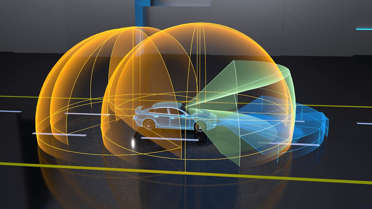
In such cases, lidar (Light Detection and Ranging) systems are used to detect objects and map their distances. Lidars can calculate these distances in real time. They are doing that by discharging laser light, measuring how long it takes the light to hit an object or surface and reflecting back to the sensor. After that, they make 3D representations of the objects.
In many cases, Lidar sensors are used along with other sensors like radars and cameras. The lidar data usually needs to be acquired together with the data from other types of sensors and data sources (analog sensors, CAN bus, etc.). The challenge for the manufacturers is to synchronize and optimize the quality of all the acquired data from different data sources.
The optimal way to avoid non-compatibilities, or even potentially misleading results due to synchronization issues would be to use a DAQ solution that can offer synchronized acquisition of all data sources. But, is that even possible?
Multifunctional solution
We have developed a simple, yet powerful DewesoftX Velodyne Lidar module which meets the requirements of the measurements needed for the automated vehicles. It provides a flexible measurement solution to synchronize data from Velodyne lidar sensors with other acquired data in the DewesoftX software.
The DewesoftX Velodyne module supports the complete Velodyne lidar family. Velodyne is a company from California, United States, that manufactures state-of-the-art Lidar sensors for various applications. Communication and connection of single or multiple lidar devices are done over the Ethernet protocol.
Velodyne Lidars are with other GNSS devices (DS-IMU, DS-VGPS-HS, …) synchronized with a GPS PPS signal, where the GNSS receiver is the source of NMEA GNSS messages for the LIDAR sensor. In order to obtain PPS synchronization for Velodyne Lidar, it needs to be physically connected to the GNSS device and properly selected in DewesoftX DAQ software.
Velodyne Lidars are synchronized over GPS PPS signal with NMEA GNSS messages which are also available in the DewesoftX DAQ software as standard navigation channels from the module.


The DS-IMU inertial measurement unit combines multiple sensors such as:
gyroscopes,
accelerometers,
magnetometers,
pressure sensors, and a
GNSS receiver.
DS-IMU devices are fully compatible to be connected and synchronized with the Velodyne lidar over GPS PPS signal.
The DS-IMU devices can also be connected in a soft-sync setup. Status and the RPM setting of the Lidar can be done directly inside the DewesoftX software. No other software is needed to perform measurements with the Lidar sensor.
Two main channels are available from the Velodyne Lidar sensor - distance and intensity of points. Visualization of the point cloud is handled by the map display widget where the open street maps or satellite image layers are overlaid with the point cloud. All the map layers can be downloaded inside DewesoftX and in case there is no actual internet connection on the measurement field reused in the offline mode. Equally to the map layers, a map of choice can be imported as well.
With DewesoftX data acquisition software, the DAQ system combines data such as:
Velodyne Lidar sensor data,
vehicle CAN bus data,
GNSS data and orientations,
braking distance calculations,
driving robot data, and
video cameras.
Coupled together in one DAQ system DewesoftX software ensures smooth data synchronization, visualization, storage, and data comparison.

Measurement setup
The goal of our measurement setup was to test:
The responsiveness of the Lidar data inside DewesoftX software.
The synchronization compatibility with other data sources such as CAN, GPS, and video.
The ease of DAQ setup to acquire data from Velodyne Lidar, DS-IMU2, and CAN bus data from the passenger vehicle.
The video camera was added to the data acquisition system for a better preview of the driving surroundings. It is a very useful feature when analyzing the data file that can be added for free to any Dewesoft DAQ system.
Data acquisition equipment used
Data acquisition system:
Dewesoft DS-IMU2 device - Inertial measurement unit and GNSS receiver with GPS/GLONASS support and 2 cm position accuracy with RTK option
Video camera
Dewesoft DS-CAN2 - 2-channel USB CAN interface for vehicle OBD-II or SAE J1939 data acquisition
Software
DewesoftX data acquisition software
Velodyne Lidar module (with 1200 RPM rotational velocity)
Setup diagram schematics
The configured system obtained GPS PPS synchronization on all devices. The DS-IMU2 was placed on top of the vehicle’s roof, while the Velodyne lidar sensor was placed on the hood. The video camera was placed on top of the Lidar sensor. The Dewesoft DS-CAN2 device was connected to the vehicle’s OBD-II port.


Data analysis
The visual display in DewesoftX provided a nice preview of the surrounding environment. For lidar visualization, we are normally using the map widget. It offers seamless visualization of lidar data, where coloring represents the laser intensity and visualization lines representing the laser points of different objects. Two Map widgets were used to show:
Left map: positioning and track view from the DS-IMU2 device with velocity color scale
Right map: lidar point cloud visualization with lidar intensity coloring applied


Lidar intensity means the collected laser intensity returns (power returned/power emitted) that are influenced primarily by distance and target reflectivity, while the lidar distance is visually applied as a real distance from the default Lidar position.
Lidar distance data is output as a matrix of point data for each lidar laser. It can furtherly be used to give feedback to the vehicle or analyze distance relations of the vehicle and surrounding objects. It is used for classifying the traffic scenes, detecting and identifying the objects, etc.
For the application, we have used the 1200 RPM rotational velocity of the lidar sensor. The acquisition of the intensity and distance Lidar data visually resulted as really responsive inside DewesoftX software. Lidar and GNSS data from DS-IMU2 are synchronized down to each acquired sample, which proves overall synchronization compatibility.
Additionally, we used a simple web camera linked to the video camera widget that shows a synchronized camera image of the driving environment. A recorder widget is used to display any measurement data channel of choice. In our case, we used two digital recorders that show current driving velocity and the number of GNSS satellites that are visible to our GNSS receiver.
All parameters, also the ones that are not applied on this particular screen, are saved inside the Dewesoft data file. They can be additionally added to the analysis screen or can be exported in various formats for further development calculations and simulations.
Conclusion
Lidar sensors play an important role in the development stage and real-world use of autonomous driving vehicles. Lidar sensors are important for ADAS testing as well as for non-automotive applications. The number of companies using lidar sensors is increasing fast. That’s why the acquisition and testing of Lidar parameters and their overall synchronization are very important.
Dewesoft now supports lidar measurements with the Velodyne Lidar module. Integrating and setting up all the sensors in DewesoftX software was pretty simple. It took us about 15 minutes to connect and set up the entire data acquisition system.
Dewesoft provides a simple and flexible solution for different types of measurements on all types of vehicles. The data from various sensors and data sources can be combined, synchronized, and visualized in one easy-to-use setup.