


What Is Signal Conditioning or Signal Conditioner?

March 31, 2026
In this article we will discuss signal conditioners and what they do in Data Acquisition (DAQ) systems, with enough detail so that you will:
See how signal conditioners work
Learn how they are used within DAQ systems
Understand their importance in the signal chain
Are you ready to get started? Let's go!
Introduction
Analog signals need to be correctly "prepared" before they can be converted into digital form for further processing. Signal conditioning is an electronic circuit that manipulates a signal in a way that prepares it for the next stage of processing. Many data acquisition applications involve environmental or mechanical measurements from sensors, such as temperature and vibration. These sensors require signal conditioning before a data acquisition device can effectively and accurately measure the signal.
For example, thermocouple signals have very small voltage levels that must be amplified before they can be digitized. Other sensors, such as resistance temperature detectors (RTDs), accelerometers, and strain gauges require excitation to operate. All of these preparation technologies are forms of signal conditioning.
Signal conditioning is one of the fundamental building blocks of modern data acquisition (aka DAS or DAQ system). The basic purpose of a data acquisition system is to make physical measurements. They are comprised of the following basic components:
Sensors
Signal Conditioning (this article)
Analog-to-Digital Converter (ADC),
And some sort of computer with DAQ software for signal logging and analysis.


Learn more about data acquisition:


What do signal conditioners do?
Data acquisition systems need to connect to a wide variety of sensors and signals in order to do their job. Signal conditioners take the analog signal from the sensor, manipulate it, and send it to the ADC (analog-to-digital converter) subsystem to be digitized for further processing (usually by computer software).
As the name implies, they are in the business of conditioning signals so that they can be converted into the digital domain by the A/D subsystem, and then displayed, stored, and analyzed.
After all, you cannot directly connect 500V to one of the inputs of an A/D card - and thermocouples, RTDs, LVDTs, and other sensors require conditioning to operate and to provide a normalized voltage output that can be input into the A/D card.
Signal conditioners types
In the world of electric sensors, we need different types of signal conditioning circuits in order to properly condition signals coming out from those sensors.
Types of signal conditioners according to physical value measurement
Voltage and high-voltage signal conditioners
Current signal conditioners
IEPE signal conditioners (or ICP/piezoelectric signal conditioners)
Charge signal conditioners
Strain gauge signal conditioners
Load cell signal conditioners
Pressure sensor signal conditioners
Thermocouple signal conditioners
RTD signal conditioners
Thermistor signal conditioners
Torque signal conditioners
LVDT signal conditioners
AC signal conditioning
DC signal conditioning
Digital signal conditioners
Frequency signal conditioners
Types of signal conditioners according to features
We can also group signal conditioners according to features. Some of those can be classified as:
Universal Signal Conditioners A universal signal conditioner is a versatile device that supports a variety of sensor types—including current, voltage, thermocouples, RTDs, potentiometers, and linear resistance sensors—eliminating the need for separate conditioners for each sensor type. These conditioners feature a programmable module that can be customized to meet specific input/output requirements.
Multi-Channel Signal Conditioners Similar to universal signal conditioners, multi-channel signal conditioners offer expanded capabilities. Unlike universal conditioners, which support only one input and output, multi-channel conditioners provide additional input/output options, allowing for more complex configurations.
Isolated Signal Conditioners Isolated signal conditioners are essential in environments where signal transmission requires electrical isolation to avoid physical connections. These conditioners prevent ground loop currents and shield control systems from electrical noise and transients that can occur under unpredictable field conditions.
Signal Conditioner Splitters Signal conditioner splitters take a single input signal and distribute it as two identical outputs across separate, isolated channels. This isolation is critical in preventing ground loops and transient disruptions. Such devices are particularly useful in applications where measurements are needed in two different locations from one source.
For more details about each type also look at the table under the section common types of signal conditioners.
Top requirements of signal conditioners
Today signal conditioners include some of the required elements that make them useful for modern data acquisition systems. These elements are:
Electrical isolation
The right connectors for sensor connections
Measurement range selection
Signal filtering (e.g. anti-aliasing filtering)
Conformance with sensor requirements.
We will now look at each of these elements of signal conditioners.
Check out Dewesoft's data acquisition systems which offer high-end signal conditioning for any sensor.


Electrical or galvanic isolation
The best signal conditioners provide electrical isolation between the inputs and their outputs. Isolation reduces noise, prevents ground loops in the measuring chain, and ensures accurate measurements.
Sometimes also referred to as galvanic isolation, electrical isolation is the separation of a circuit from other sources of electrical potential. This is especially important with measuring systems because most signals exist at relatively low levels, and external electrical potentials can influence the signal greatly, resulting in wrong readings. Interfering potentials can be both AC and DC in nature.
For example, when a sensor is placed directly on an article under test, (e.g. a power supply) which has potential above ground (i.e., not at 0V), this can impose a DC offset on the signal of hundreds of volts. Electrical interference or noise can also take the form of AC signals created by other electrical components in the signal path or in the environment around the test. For example, fluorescent lights in the room can radiate 400 Hz which can be picked up by very sensitive sensors.
This is why the best data acquisition systems have isolated inputs - to preserve the integrity of the signal chain and ensure that what the sensor outputs is truly what has been read. There are several kinds of isolation techniques employed today.
It is important that isolation is in place not just from channel to ground, but also from channel to channel. Excitation lines should also be isolated where necessary. A comprehensive isolation system prevents damage to the systems from excessive voltage and avoids ground loops and wrong measurements.
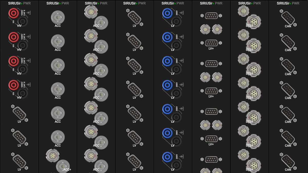
As one example, signal conditioners of Dewesoft’s SIRIUS DAQ systems provide isolation of 1000V (the HV high voltage module is additionally rated CAT II 1000V).
Learn more about DAQ isolation:

The right sensor connections
The best signal conditioners are fully adapted to the sensors that they are intended to be used with. At the most basic level, this includes the use of the appropriate connector(s) for these sensors.


Voltages are typically handled with BNC connectors (up to 50V), and safety-type banana plugs above that. For voltage output sensors that require sensor supply by the signal conditioner, a multi-pin connector is used, such as compact and high-reliability LEMO connectors, or less-expensive (but larger) DB9 (DSUB-9) connectors. This is why most manufacturers, Dewesoft included, make their voltage signal conditioners available with a variety of connector types.
Accelerometer sensors usually employ either a BNC or a 10-32 microdot connector.
Thermocouples almost always use the mini-blade type of connector now, and they are colour-coded by type according to international standards.
Strain gauges are usually sold with bare wires because there is no industry standard for the multi-pin connectors that should be used, or for the wiring method that the engineer will choose (3-wire, 4-wire, sense lines or no sense lines, etc). The most commonly employed multi-pin connectors used in strain gage applications are compact and high-reliability LEMO connectors or less-expensive (but larger) DB9 (DSUB-9) connectors.
Connectors that are highly reliable, and in some cases water-proof, are essential for signal conditioners.
It should be mentioned that for data acquisition systems that are permanently mounted in an industrial measurement environment, these requirements are different. Unlike a typical data acquisition system that is going to be moved around and used for a variety of applications, these systems are “fixed” and do not change. Fixed or embedded systems are typically outfitted with screw terminal block connectors, which are very efficient and low-cost. They do not have to be rugged or tamper-proof since they are locked away.
Measurement range selection
The ability to select the proper measuring range for a given sensor is the most basic essential function of a signal conditioner. In order to get the best possible results from their measurements, engineers must be able to set the voltage level (or gain in general) of the conditioner.
For example, if you are trying to measure a voltage that spans from ±2.5mV (±0.0025V), but your conditioner only has a ±50V range, your signal will be extremely small within the resulting gain aperture to the point of being unusable. Similarly, if your voltage is going to span ±100V but your only range is ±50V, half of the signal will be clipped by the conditioner and will never be measured.

")
Providing a suitable selection of ranges given the conditioner type and its application is therefore always a critical requirement of a signal conditioner.
Signal filtering
Aside from setting the input gain, perhaps the next most important function of a signal conditioner is to provide some manner of filtering. At the very least, a two or four-pole low-pass filter is often needed to suppress or reduce electrical noise, which can get into the signal from the testing environment.

 input is smoothed with an IIR filter (blue signal)")
One kind of filtering must be done in hardware, before the ADC process: anti-aliasing filtering. This is a special kind of filtering that prevents wrong readings that can happen when the sample rate is set too low compared to the frequency content of the signals being measured. Anti-aliasing filters (AAF) prevent wrong readings by automatically adjusting the front-end filter according to the selected sample rate. There are more details about AAF in the article called “What Is An A/D Converter?”
Virtually all other filtering can be done either in hardware or in software. For example, Dewesoft DAQ systems provide hardware filtering wherever it might be required by the application, for example, the high-pass hardware filters in their CHG (charge amplifier) and ACC (IEPE amp), which are useful for AC coupled accelerometer outputs prior to signal integration.
Other hardware filters are provided within Dewesoft DAQ hardware. But in addition, a powerful suite of software filters is provided for each channel. In fact, software filters can be applied non-destructively in Dewesoft DAQ systems, before or after recording (or both). This allows engineers to capture both the raw signal and one or more filtered copies of the signal, and compare them (as shown in the diagram above where a raw and filtered signal can be overlaid on the same graph).
Conformance with sensor requirements
Each signal conditioner must be perfectly adapted to the sensor with which it will be used. Sensors have vastly different requirements based on their operating principles, which the conditioner must be adapted to.
For example, a strain gage (aka strain gauge) signal conditioner must provide excitation voltage to the strain gage sensor. And since engineers use anywhere from one to four gages when making strain measurements, the conditioner needs to be adaptable to handle a quarter, half or full-bridge configuration.
Strain gages require perhaps the most complex setup in the world of signal conditioning, therefore the best conditioners provide a wide range of features including bridge completion, shunt cal, sense line hookup to suppress self-heating and sensor line resistance changes, and more.

 setup screen")
Next, we will look in more detail at each of the major signal conditioner types, and discuss their requirements in more detail.
Common types of signal conditioners according to the signal type
Today’s signal conditioners need to be able to interface with these popular sensors:
| Signal Type | Sensor | Signal Conditioner | Basic Requirements |
|---|---|---|---|
| Low voltages | (Direct) | Low voltage signal conditioner | Multiple ranges, Isolation, conformance with safety standards (above 50V), selectable filtering |
| Kilo volts | Potentiometric Transducers | High voltage signal conditioner | Multiple ranges, Isolation, conformance with high voltage safety standards, selectable filtering |
| Temperature | Thermocouple | Thermocouple signal conditioner | Isolation, Linearization from various types of sensors, cold junction compensation |
| Temperature | RTD | RTD signal conditioner | Isolation, sensor supply, sense line adjustment, scaling from various RTD types |
| Shock and Vibration | IEPE accelerometer | IEPE / ICP / piezoelectric signal conditioner | Multiple ranges, Isolation, constant current sensor supply at a nominal compliance voltage, selectable filtering |
| Shock and Vibration | Charge accelerometer | Charge signal conditioner | Multiple ranges, Isolation, conversion of pC ion stream to voltage, selectable filtering, including high-pass |
| Strain, Pressure, Force | Strain Gage (bridge-type sensors) | Strain gage signal conditioner | Multiple ranges, Isolation, sensor supply, bridge balance, shunt calibration, sense line adjustment, selectable filtering |
| Distance, Displacement | LVDT | LVDT signal conditioner | Multiple ranges, Sensor supply, zero adjustments, isolation |
| Distance, Displacement | String Potentiometer | Resistance signal conditioner (normally Strain gage type) | Multiple ranges, sensor supply, zero adjustments, selectable filtering |
| Digital Inputs | TTL events, Gear Tooth, encoders | Digital signal conditioner | Isolation, adaptable to a variety of discrete inputs, conversion of raw counts to RPM, and other functions |
Hard requirements such as isolation, sensor supply, input gain, and anti-aliasing must be done in hardware. Most filtering (except for anti-aliasing filtering) and linearization can be done in software.
Low voltage signal conditioner
If we look at voltage measurement, it would seem that this would be the easiest task because the signals already exist as a voltage. However, the voltage can span from very small potentials in the billionths of volts, up to tens of thousands of volts. It can also exist as an alternating current (AC) or direct current (DC).
Voltage potentials (electric potential) can exist far above the ground, or be centered around 0V. The challenges and therefore the processes are essentially the same as with any other physical phenomena that we want to measure. Small voltages must be amplified to a nominal digitizing level (typically ±5V). Galvanic isolation is often needed to prevent cross-talk and ground loops which can destroy the integrity of the measurement by introducing wrong values and offsets.
It is sometimes required to AC couple a voltage to remove the DC component or provide low or high-pass filtering in order to achieve certain measurement goals.

")
The SIRIUS LV DAQ module from Dewesoft is available with a variety of connector types to suit the application: BNC, safety banana jacks, DSUB9, and others upon request.
Learn more about voltage measurement:

High voltage signal conditioner
Large voltages must be stepped down to the nominal digitizing level. There are sensors for this, including potential transducers (PTs) which can divide the thousands of volts on an electrical transmission line down to a safe level. The output of a PT is then fed into the voltage signal conditioner, which further prepares it for digitizing.
Any signal conditioner used for high voltage measurement must be strongly isolated for the safety of the human operators of the equipment, and to avoid system damage or destruction.
It must be designed with the proper connectors. For temporary hook-ups, safety/insulated banana jacks are common. For permanent hook-ups, shielded screw terminals are common. Exposed contact connectors must be avoided


A good example of a powerful high-voltage signal conditioner is the SIRIUS HV module from Dewesoft.
Learn more about voltage measurement:
Thermocouple signal conditioner
A simple thermocouple sensor requires a high-quality signal conditioner in order to work. Although a T/C is passive, not requiring excitation or sensor supply, the tiny voltage potential that it generates at the connector side of the sensor must be isolated, amplified, and linearized. In addition, it needs a reference in order to provide an absolute temperature reading - otherwise, it can only produce a relative temperature reading, which is not very useful.
The amplification, isolation, and compensation aspects must be provided by the signal conditioner in hardware, while the linearization task can be done either in hardware or via software.
The “reference” mentioned above is known as cold junction compensation. The measuring end of the sensor is called the “hot joint” (the junction of the dissimilar metals used in the construction of a thermocouple), while the other end - where we receive the signal - is the cold junction of the sensor. This cold joint is where the dissimilar metals that comprise the thermocouple meet the copper wires of the DAQ system.
A tiny cold junction compensation (CJC) chip is provided here either inside the signal conditioner or within an annex box that connects to the conditioner. This CJC must be protected against ambient temperature swings caused by moving air or sunlight. They are typically installed within a special paste to keep their temperatures stable.
The science of making an accurate thermocouple signal conditioner cannot be overstated. Without serious attention to detail, accurate and linear thermocouple measurements cannot be made.
Other important features of a good thermocouple signal conditioner include:
High-resolution ADCs
24-bit resolution is recommended with thermocouples. Why? A type K thermocouple sensor has a measuring range of -270° to +1260° C (-454° to 2300° F). That is a huge range.
Using a 24-bit ADC provides a vastly more amplitude axis than a 16-bit ADC (remember that each bit doubles the number of values from the one before).
Proper connector type and color identification
Today, the mini-blade thermocouple connector type has become the de facto standard, along with the color coding that allows easy visual identification of the thermocouple type. Connecting a type K thermocouple to a signal conditioner designed for Type S or T, for example, will result in wrong readings.
Fixed-type thermocouple signal conditioners
A “fixed type” thermocouple signal conditioner is one that has been made to be compatible with a specific thermocouple type, like Type J, K, or T, for example. Since Dewesoft offers high-performance universal signal conditioners for all of its DAQ systems, they have created DSI adapters for various sensors - including the most popular thermocouple types.


DSI-TH-x series adapters feature high-accuracy cold junction reference measurement. 1 m thermocouple cable is included with a mini TC connector. Supported thermocouple types:
DSI-TH-C - thermocouple type C
DSI-TH-J - thermocouple type J
DSI-TH-K - thermocouple type K
DSI-TH-T - thermocouple type T
DSI adapters can be used with all Dewesoft DAQ systems and host amplifiers featuring DSUB9 connectors - including SIRIUS, DEWE-43A, KRYPTON, and IOLITE.
Universal thermocouple signal conditioners
A good example of a universal type thermocouple signal conditioner is the KRYPTON isolated thermocouple modules from Dewesoft, available with 8 or 16 channels per module. These signal conditioners sample each channel at 100 S/s with a 24-bit resolution sigma-delta ADC per channel. Their input accuracy is typically ±0.02% of reading ±100 μV. They provide 1000V of isolation per channel, protecting the millivolt signals generated by thermocouples from interference.


Because the linearization can be performed very accurately and quickly by the included DewesoftX data acquisition software, these modules are compatible with all major thermocouple types in use today: K, J, T, R, S, N, E, C, U, and B.
White-color thermocouple connectors are used to indicate that the inputs are universal. The engineer simply selects the T/C TYPE that they are using on the channel setup screen within the Dewesoft X software, which then applies the correct linearization.
KRYPTON modules connect together via a single high-speed EtherCat interface, which carries power, data, and synchronization. They are made for harsh environments with high shock and vibration, water, dust, and smoke, and from very low to high temperatures.
Learn more about temperature measurement:

RTD signal conditioner
Although it also measures temperature, an RTD (resistance temperature detector) is a very different kind of temperature sensor compared with the thermocouple. The most important distinction is that RTDs are not passive sensors - they must be powered by the signal conditioner.


A good example is the IOLITE 8xRTD module from Dewesoft. This is an 8-channel RTD signal conditioning module with an integrated 24-bit ADC per channel.
It supports both 3-wire and 4-wire RTD hookups. Note that 2-wire hook-ups are typically not recommended because the lead wire resistance gets added to the measurement resulting in artificially high-temperature readings, and there is no way to know exactly how much the measurement is wrong.
3-wire vs. 4-wire RTD connections
In a 3-wire hook-up, a third wire is used to detect the average lead wire resistance. The signal conditioner or accompanying software can then remove this offset in real time, resulting in a much more accurate reading.


If we measure the resistance between R1 and R2 and subtract the resistance between R2 and R3, we will get the resistance of only the measuring end of the circuit at R(b). Of course, this assumes that the resistances are all the same. We can improve the accuracy even more by adding a fourth wire, as shown below:

You might notice that this hook-up is a full bridge. Lines 1 and 4 provide power to the circuit, and wires 2 and 3 are used to read back the lead wire resistance back to the RTD signal conditioner. In this way, we can completely offset variations in lead wire resistance.
Why choose 3-wire over 4-wire?
So, if 4-wire hook-ups are always better than 3-wire, why do engineers sometimes opt for 3-wire? Usually, the answer lies in economics. If the RTDs are located a large distance from the measuring system, using three wires instead of four will save a lot of money in terms of cable cost and wiring costs. This can add up to a lot of time and money in large-scale testing systems.
Learn more about RTD measurement:

IEPE signal conditioner
Accelerometer sensors that have a tiny amplifier built into them are also known as ICP® (a tradename of PCB Piezotronics) or more generically as IEPE, which stands for integrated electronics, piezo-electric. The output of these accelerometers is a relatively high-level voltage that can be sent back to the signal conditioner on good quality cable, at less expense than the cable required by charge-type accelerometers.
But unlike charge-type accelerometers that are passive and require no power, IEPE sensors need a voltage supply from the signal conditioner. This is normally presented in a form of a constant current of 4 to 20 mA and at a compliance voltage of 25 volts (typically).

 and more.")
Since IEPE accelerometers are made for measuring AC waveforms, this DC supply can be placed on the signal lines without creating any offset or measurement error.
Thus, the fundamental requirement of any IEPE signal conditioner is that it is able to provide this constant current power. The SIRIUS ACC provides a user-selectable constant current of 2, 4, 8, 12, 16, or 20mA at a 25 V compliance voltage.
Another useful feature provided on Dewesoft SIRIUS ACC modules is a visual indicator that the sensor is connected and operating. This is done by means of a green LED around the input connector bezel that lights up when the sensor is connected and working.

IEPE sensors nearly always employ a BNC connector, therefore it is important that the signal conditioner do the same. Referring to the picture above you can see the BNC input connectors on the SIRIUS ACC slice.
TEDS sensor support is highly useful with IEPE sensors. TEDS (Transducer Electronic Data Sheet) is an IEEE 1451 standard based on storing information about the sensor inside the sensor itself, including its unit of measure, scaling factor, calibration information, and more.
Charge signal conditioner
Charge accelerometers require a signal conditioner that can read in their high impedance stream of charged ions (measured in pC, or pico coulombs), and convert them into a high-level voltage. They are based on the same piezoelectric principle as IEPE sensors (see above), but they have no built-in preamplifier. Therefore they do not require sensor power.
However, their high impedance output does not transmit as easily as the amplified output of IEPE sensors. Expensive low-noise cables must be used and kept to as short a length as possible in order to prevent noise from influencing the signal. Still, charge accelerometers are still in use because they provide the highest possible temperature operating range, up to 538° C (1000° F), and the highest possible bandwidth. Special sensors are available with even greater operating temperature spans, low and high.
The output of charge sensors can be integrated to convert acceleration to velocity, and double-integrated to provide displacement.


The SIRIUS CHG-type signal conditioners are a great example of a versatile charge mode signal conditioner. In addition to handling charge sensors, it can also act as a low-voltage conditioner and an IEPE signal conditioner.
Strain gage and load cell signal conditioner
Strain gauge signal conditioners have perhaps the most complex job in the world of data acquisition. First, they must support multiple hook-up schemes, from the relatively simple full-bridge configuration to quarter and half-bridge configurations, each with several wiring options. And when something other than a full bridge hook-up is selected, they are expected to also provide the resistors that are needed to complete the Wheatstone bridge circuit.


Of course, it must be possible to adjust the gain (aka sensitivity) of the signal conditioner. And to adjust how much voltage is sent to the strain gage sensor to power it (the excitation voltage). Filtering is almost always required with strain gauges, and this must be provided either in hardware or software, with selectable orders (filter strength).


That would seem like enough, but there are more requirements yet, including the ability to connect to one or more sense lines and use them to offset lead wire resistance changes caused by cable length and/or self-heating. Also, every strain gauge has a Gage Factor - a number around 2, which must be entered and used by the system to convert the raw mV/V return from the sensor to a microstrain reading.
As a general statement, it should be an option for the engineer to choose to use the gauge factor or not or to scale the return from the sensor in any way that they choose. For example, strain gauge conditioners are also used for load cells, in which case we might want to see the reading in weight - kg or lbs. Every option should be provided to the engineer.
All of the above features and functions, and more, are basic requirements of any serious strain gauge signal conditioner.
A perfect example of a powerful and flexible strain gage signal conditioner is the SIRIUS STG module from Dewesoft:


Learn more about strain gages:

LVDT signal conditioner
LVDT (linear variable differential transformer) transducers are used to measure linear displacement/position over relatively short distances. They consist of a tube that contains a rod. The base of the tube is mounted to a fixed position, and the end of the rod is affixed to something that moves.
As the rod is pulled out from the tube or slides back in, the sensor outputs a signal that represents the position of the rod from its starting point to its maximum deflection. The rod does not touch the inside of the tube, making it virtually frictionless, and the LVDT itself contains no electronics, making it popular in harsh environments.
An LVDT signal conditioner must provide the AC excitation that the transducer requires for operation. This AC drives the primary coil, which induces an output from each of the secondary windings, which are located toward either end of the tube. The signal conditioner must be able to take in and scale the differential output signal appropriately for display and measurement.
A good example is the SIRIUS STG with the DSI LVDT adapter from Dewesoft. Since the STG module has almost everything needed to perform as an ideal LVDT signal conditioner. All we add is a small adapter called the DSI-LVDT to the input connector of the STG module in order to complete the signal conditioner for use with LVDTs.

The DSI-LVDT has a TEDS chip inside it. When plugged into the SIRIUS-STG, the signal conditioner reads the information from the chip and automatically sets itself up as an LVDT signal conditioner. The engineer can further perform zero balancings and EU input and scaling if they want to. The DSI-LVDT generates the 4 to 10 kHz excitation that the sensor requires, and allows phase adjustment via a small potentiometer.
String pot signal conditioner
A string pot or string potentiometer is a sensor that measures distance. It is configured as housing that contains a reel of rugged string that is spring-loaded so that it automatically winds back into the housing when the string is released.
The housing is mounted in a fixed position, while the end of the string is attached to something that will move, such as a door, a bracket, or another object that will move back and forth with respect to where the housing is mounted. A good example is a movement between the “truck” of train wheels and the body of the train, which rides above it on a suspension system.
While a string pot is similar in operation to an LVDT, it is different in how it works. While an LVDT uses a differential AC potential to measure the position of a sliding rod, a string pot uses variable resistance to calculate how much string has been deployed.
And from a mechanical point of view, the LVDT’s rod must move along a plane parallel with its tubular housing, while the string pot’s string is free to move in a wide arc from its point of emergence from the housing.
In order to condition a string pot’s output, we need a signal conditioner that can provide the excitation needed to invoke a resistance change from the sensor, and then read in the output. It is also necessary to be able to scale the reading into a useful unit of measurement, such as mm, cm, m, inches, feet, etc.
A good example is the SIRIUS STG module from Dewesoft. As a strain gauge module, it is in the business already of providing excitation and reading in tiny voltage potentials. It can make resistance measurements in a basic half-bridge configuration. No additional adapter is needed in order to directly connect a string pot to the Dewesoft STG signal conditioner.


For more details about the SIRIUS STG, see the Strain Type signal conditioner above.
Digital input signal conditioners
Digital inputs run the gamut from recording simple on-off signals to handling a highly precise quadrature encoder, or gear tooth sensor that allows you to measure RPM, and other variants. They are referred to as digital because their signal is in the form of either high or low, unlike analog signals that have a waveform with many values between the highest and lowest ones that must be measured.
Discrete digital inputs


The simplest of digital inputs is the on/off type of signal that looks like a square wave if you look at it. These are sometimes referred to as discrete channels or event channels. Since they have only two states, they are often used to show the state of a door being open or closed, or a circuit is on or off, and a thousand other yes/no possibilities that we might need to measure.
Discrete inputs are normally output from a relay or transducer at TTL (transistor to transistor logic) levels, which are based on a 5V pull-up. In theory, the perfect TTL on/off signal would be 0V representing OFF (meaning a digital value of 0), and 5V representing ON (meaning the digital value of 1). However in practice, it is nearly impossible to achieve such precision, so the acceptable ranges have become 0 to 0.8V for OFF and 2V to 5V for ON.


These digital inputs are easily handled by Dewesoft’s SuperCounter® digital inputs, available on virtually every Dewesoft model DAQ system. These counter inputs have three lines (A, B, Z) which can handle encoders and RPM sensors - or you can use them as three separate discrete digital inputs (IN0, IN1, IN2). It is important to note that Dewesoft’s digital lines are sampled far above the sample rate selected by the user for their analog inputs, but are precisely aligned on the time axis with the analog inputs.


In addition, for large numbers of plain digital inputs, the Dewesoft IOLITE offers a 32-channel digital input module. This model 32xDI with easy screw terminal hookup and sensor power supply is ideal for high channel count data acquisition and control applications.


Tacho, RPM, and angle sensors
Dewesoft SuperCounter inputs can measure RPM and angle output values of rotating machines from a wide variety of RPM sensors, speed sensors, and encoders. Compared to standard counters, which only output integer numbers one sample later (e.g. 1, 1, 2, 2, 3, 4), SuperCounters can extract highly precise values like 1.37, 1.87, 2.37 between the analog samples, and fully synchronize them with the analog channels.
This is done by measuring the exact time of the rising edge of the signal with an additional counter. Dewesoft SuperCounters run on a 102.4 MHz time base, independent from the analog sampling rate.
There are several common sensors that are used for counting events, measuring speed, RPM, angle, etc. These include:
Encoder with 1, 2, or 3 outputs (A, B, and Z reset signal)
Linear pulses and pulse encoder
An optical tacho probe (1 pulse per revolution) a reflective sticker angle and RPM can be calculated.
Gear tooth sensor with missing teeth (e.g. 60-2) or double teeth, CDM, CDM with zero, CDM with TRG
All of these can be connected to the Dewesoft SuperCounter and configured easily within the software. The outputs are perfectly synchronized with the analog data also being measured, allowing for advanced applications such as rotational and torsional vibration, combustion analysis, order tracking analysis, balancing, human body vibration, etc. to be performed.
Dewesoft X software has a built-in library of typical sensors, but it also has a flexible database that the engineer can use to create new sensors, name them, and call them up anytime in the future.

