


What Is an Inertial Navigation System?

November 20, 2023
In this article we will learn about IMU (inertial measurement units) and INS (inertial navigation systems), describing them in enough detail that you will:
See what inertial systems are and what they can do
Learn how inertial systems work
Understand how inertial systems are used in a range of applications
What is an IMU or IMU sensor?
An IMU is an abbreviation for Inertial Measuring Unit. It is the sensors, including gyroscopes and accelerometers, that measures the angular position and displacement of an object in three-dimensional space.
What is an INS?
An INS is an abbreviation for Inertial Navigation System. It includes the IMU sensors and their gyroscopes and accelerometers, as well as a sensor for receiving absolute position data from GNSS satellites in space. It may additionally be equipped with magnetometers for measuring magnetic fields in three-dimensional space.
An INS adds advanced data processing, including Kalman filtering and other processing. Referencing the known starting position, it uses the outputs from the IMU to determine the real-time position and vector of an object. This “object” can be a car, submarine, airplane, or any machine that operates in three-dimensional space.
Why do we need inertial navigation systems?
Almost every car, plane, ship, and smartphone today has some kind of navigation system. Your location can be shown on a map using trilateration position data from GPS/GNSS satellites in space, or in the case of your smartphone, a trilateration position from cell phone towers that are at known, fixed locations.
But what if we don’t have access to satellites or cell phone towers? For example, how does a submarine navigate? Once a submarine submerges and moves away from a known starting point, it has no access to satellites or any other external source of position data.
There is no “GPS” under the water! So how does the submarine crew know where they are located? How do they know precisely how fast they are moving and their exact position, orientation, heading and bearing in a three-dimensional undersea world? INS systems are the answer.
In a less dramatic example, what about motor vehicles that travel in tunnels or other obstructions to the GPS/GNSS satellite system or cell phone towers? How can they keep track of their location and vector?


This is where INS (Inertial Navigation Systems) comes into play. An INS uses a collection of extremely precise accelerometers, gyroscopes, and magnetometers combined with advanced processing, to calculate an object’s position relative to a known starting point, speed, and direction. Once a submarine’s INS is calibrated to a known reference point, it can “dead reckon” very accurately from that point forward.
A system that uses “dead reckoning” uses a known starting position, and then it adds the IMU/INS data to that position in order to deduce the object’s current position and vector. No INS is perfect, so inaccuracies will accumulate the longer the system is a dead reckoning.
In the case of submarines, they are often located underwater so deep that they cannot deploy an antenna that floats to the surface and connects to GPS and other GNSS systems in space. So when they cannot connect to GPS/GNSS, they use their INS system to “dead reckon” their position. Modern military submarines are equipped with incredibly accurate, low-drift INS modules.
When satellites and other external references become available again, the system is recalibrated, eliminating any errors that had accumulated during the time of dead reckoning. INS is also used by commercial and military aircraft, spacecraft, missiles, drones, and robots, and is even integrated into many mobile phones and video game controllers.


Inertial navigation can be used as a “fall-back system” that can dead reckon during a time when GPS/GNSS navigation is not available. But in the case of submarines and spacecraft, they are the primary method of navigation. Aircraft and other vehicles often use INS in close conjunction with GPS/GNSS and other absolute position references.
The IMU: the beating heart of every INS
Inside every INS is the all-important IMU. An IMU is a sensor package that contains at least three orthogonal gyroscopes and three orthogonal accelerometers. They are also sometimes equipped with three magnetometers that measure magnetic dipole moments, aka magnetic fields. IMUs are used to measure the objects:
Angular rate - the rate at which an object is rotating around its axis
Specific force - the difference between absolute acceleration and gravitational acceleration
Orientation - the object’s position in three-dimensional space.
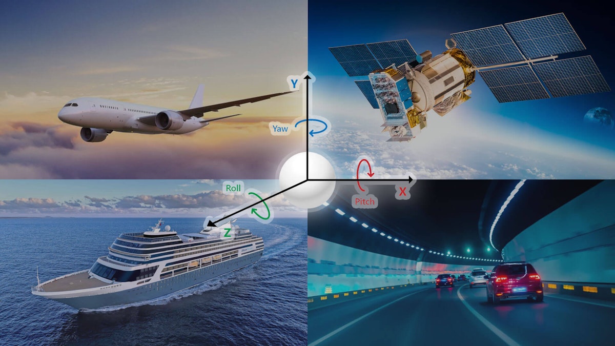
Basically, each of the three main axes (X, Y, and Z - also known as roll, pitch, and yaw) is equipped with at least one accelerometer, one gyroscope, and (usually) one magnetometer.


Why do we need three sets of sensors?
A single inertial sensor can only measure along a single axis. But we move in three-dimensional space, so we mount three inertial sensors together in an orthogonal cluster.
An inertial system consisting of three accelerometers and three gyroscopes is called a 6-axis system (two measurements along three axes is a total of six measurements). When we want to sense the magnetic fields for navigation purposes, we add a magnetometer along each axis, for a total of nine sensors.
A typical IMU measures the raw angular velocity of the object that it is connected to. It also measures the specific force/acceleration and magnetic fields.
When we add advanced signal processing and data filtering such as Kalman filtering, described in the next sections, our IMU becomes part of a larger system called an INS or inertial navigation system. When it is used for navigation, we can also refer to an INS as an AHRS, or Attitude and Heading Reference System.
What’s the difference between an IMU and an INS?
The IMU (inertial measuring unit) is essentially the sensor subsystem of an INS (inertial navigation system). The INS takes the raw outputs from the IMU, processes them, and calculates changes in an object’s relative motion. The INS references these changes to the known starting point, speed, and direction, providing a real-time position and vector output.
IMUs can be completely integrated into an INS, or they can be separate pieces of hardware that connect to an external INS or similar system.
The INS calculates and outputs:
Attitude - pitch, roll, and yaw centered about the object’s center of gravity
Position, position velocity, and orientation - in three-dimensional space
Linear velocity - a vector quantity that consists of both magnitude and direction
Angular rate - the rate at which an object rotates about its axis
Key INS technologies
GNSS receivers
To connect to the satellites in space a sensor is required. A “GPS” or GNSS sensor is usually a sealed dome-like structure with antennae inside it. It must be positioned with line-of-sight to the sky in order to receive data from the various GNSS constellations located in space.


Learn more about:

Gyroscopes
Inertial sensors were created long before the semiconductor. Classic mechanical gyroscopes are mechanical structures consisting of a spinning rotor that is free to assume any orientation.
Because of the conservation of angular momentum, the orientation of the rotor is not affected by tilting or rotation of any part of the outer frame or inner gimbals.

Today, the mechanical gyroscope is still heavily used in applications that require the most accuracy and long-term stability. They are still the sensor of choice for submarines, for example. A large submarine has plenty of room for this large mechanical structure, and its weight is not much of a concern.
But starting in the 1960s, new technologies have been developed to allow a smaller, lighter, and solid-state device to act as a very accurate gyroscope. These include:
RLG - Ring Laser Gyroscopes
FOG - Fiber-optic Gyroscope
Quartz/MEMS Gyroscopes
Ring laser gyroscope (RLG)
Ring laser gyroscopes operate on the principle of the Sagnac effect. A single laser is split into two beams that move around in the ring in opposite directions. The sensor measures the interference pattern caused by the movement of the structure, along a single axis.
The RLG is typically filled with Helium-Neon. Electrodes excite light waves traveling in opposite directions. The invention of the Ring Laser Gyroscope is widely attributed to Honeywell aerospace engineers in the 1960s.
Learn more about ring laser gyroscopes
Fiber optic gyroscope (FOG)
FOG gyroscopes are similar to RLG gyroscopes, detecting movement using the Sagnac effect. Laser beams are injected into a single fiber optic cable, but they travel in opposite directions. The beam moving in the direction of the frame’s rotation arrives a little faster than the other beam. Interferometry is used to measure this phase shift and calculate the amount of movement.
Learn more about FOG gyroscopes
Quartz/MEMS gyroscope
MEMS stands for “micro-electro-mechanical systems.” These are small sensors and devices that can be manufactured using many of the same methods by which semiconductors are made. It is therefore possible to build a gyroscope small and inexpensive enough to be installed within a smartphone, video game controller, and thousands of more machines.
Quartz crystals react to motion, operating as a Coriolis sensor. Coupled with a tuning fork resonator, a quartz sensor produces an output that can be processed by the onboard microelectronics. Despite their small size and relatively low cost, MEMS gyroscopes are accurate enough for a wide range of applications.
Learn more about MEMS gyroscopes
Gyro sensor types by application
Based on their accuracy and drift performance, gyroscopes can be roughly grouped into four categories:
Consumer - smartphones, gaming consoles, and other consumer products
Industrial - UAVs (unmanned aerial vehicles), including drones; manufacturing processes and environments
Smart weapons - and related military equipment
Navigation - aircraft, spacecraft, submarines, automobiles, farm and construction vehicles, land-based military vehicles
Here is an overview of how the various gyroscope technologies fit into these applications. RLG, FOG, and Quartz/MEMS gyros are used across the widest range of applications. RLG and FOG have replaced mechanical gyroscopes in some, but not all, applications. Mechanical gyroscopes still provide the best long-term stability and are therefore preferred for critical dead reckoning applications in submarines and some aircraft.
Comparison of major gyroscope types
| / | Mechanical | FOG | RLG | Quartz/MEMS |
|---|---|---|---|---|
| Applications | Submarines, spacecraft, aircraft | Smart weapons, many automotive and commercial, and military aerospace and navigation applications | Smart weapons, many automotive and commercial, and military aerospace and navigation applications | Consumer-grade, industrial grade, tactical grade markets |
| Pros | Best long-term stability | Small, solid-state, rugged, and less expensive than mechanical gyros | Small, solid-state, rugged, and less expensive than mechanical gyros | Same as RLG and FOG, but even smaller and less expensive |
| Cons | High cost, relatively large/heavy structure | They lack the ultra long-term stability of mechanical gyros | They lack the ultra long-term stability of mechanical gyros | They lack the ultra long-term stability of mechanical gyros |
Accelerometers
Accelerometers are sensors that measure a change in velocity over time. There are several key technologies used to create these sensors. They are essentially a “proof” mass suspended by a spring. The longitudinal direction of the spring is called the “sensitivity axis.”
When the sensor is subjected to a change in velocity along this axis, the proof mass will move, compressing the spring. The amount of this compression is proportional to the acceleration, so we can measure and output this value. Acceleration is measured in g (aka “G force”), also known as meters per second squared.


Magnetometers
Everyone knows the old-fashioned compass: a magnetized needle is free to point toward the magnetic north of the earth, located near the north pole. A compass is a magnetometer in the most elemental sense. However, for our IMU and INS systems, we need to measure magnetic fields in far more detail.


Magnetometers can be based on a variety of technologies, including the Hall effect, magneto-diode, Lorentz force MEMS, fluxgate, and many more. MEMS-based magnetometer sensors are especially popular today because they can be manufactured to be quite small, accurate, and inexpensive. In many of today’s IMU, INS and AHRS systems, magnetometers provide a three-dimensional heading reference.
Learn more about magnetometers
Kalman filtering
Kalman filtering is an algorithm that essentially fuses sensor data with predictive data. This is a two-stage real-time linear quadratic equation, where the first stage predicts and weights the accuracy of various inputs, and the second stage applies a weighted average to the inputs. This recursive process improves the accuracy of navigational outputs from GPS/GNSS systems and is integral to inertial navigation accuracy.
Learn more about Kalman Filtering
Inertial applications
INS systems are widely used in a variety of applications. Nearly all of these are centered around navigation, including:
Road vehicle navigation - automobiles, trucks, busses, motorcycles
Air navigation - commercial and military aircraft
Off-road navigation - military vehicles, farm vehicles, tractors, agricultural vehicles, et al
Space navigation - spacecraft and satellites
Undersea and surface ship navigation - boats, ships, and submarines
Mining and drilling tunnels - calculating distance and direction underground
Weapons guidance - missiles and other guided munitions
Road vehicle testing - ADAS (advanced driving assistance system) testing of autonomous vehicles, test track testing
Learn more about ADAS - Advanced Driving Assistance Systems


Dewesoft IMU and INS solutions
DS-IMU1
DS-IMU1 is a miniature, ruggedized and reliable GPS-aided navigation system with up to 100 Hz output data rate.
Key features:
Combines inertial sensors together with GNSS receiver coupled in a sophisticated fusion algorithm to deliver accurate and reliable navigation and orientation
GNSS receiver supports GPS, GLONASS, BeiDou, GALILEO, WAAS, EGNOS, and GAGAN systems
IP67 & MIL-STD-810G environmental protection
Up to 100 Hz output data rate
Connected over USB
Fast and easy to install


Navion i2
The Dewesoft NAVION i2 is a GNSS-supported inertial measurement platform that measures orientation, position, velocities, and accelerations.
Key features:
Ethernet-based, enabling the remote connection to the system directly via DS-WIFI4
Dual-frequency GNSS receiver
RTK with 1 cm position accuracy
DGNSS, SBAS augmentation supported
Dual GNSS antenna measurement for accurate static heading output
PPS output for device synchronization
Fast and easy to install


DS-GYRO1
The Dewesoft DS-GYRO1 is a miniature, ruggedized and reliable inertial navigation unit.


Key features:
Combines inertial sensors in a sophisticated fusion algorithm to deliver accurate and reliable orientation
IP67 & MIL-STD-810G environmental protection
Up to 500 Hz output data rate
Connects via USB
Fast and easy to install
Third-party INS and GNSS systems support
DewesoftX software (and therefore all Dewesoft DAQ systems) are compatible with a broad range of third-party INS and IMU sensors, including:
Summary
We hope that this article has helped you to understand what IMU and INS systems are, and how they work. You have seen how important they are to a wide range of applications. Without them, submarines and spacecraft could not navigate, and land vehicles and aircraft would have a very difficult time of it.
Testing the advanced driver assistance features in today’s cars would be nearly impossible with GPS/GNSS and related technologies. As machines, vehicles of all kinds, drones, and robots become more and more a part of the modern world, the need for GNSS and navigation systems will only increase.
Key acronyms and definitions
The world of IMU and INS is filled with sometimes cryptic names and acronyms that are useful to know. Here are some of the most often used ones from this world and from related topics mentioned in this article:
| Acronym | Definition |
|---|---|
| AHRS | Attitude and Heading Reference Systems. |
| BeiDou | China’s satellite constellation and navigation system. |
| DGNSS | Differential GNSS - a ground-based augmentation system that improves accuracy to the 1-3 cm level. When GPS is the only constellation used, this is called DGPS (see below), otherwise it is referred to as DGNSS. |
| DGPS | Differential GPS - a ground-based augmentation system that improves accuracy to the 1-3 cm level. |
| EGNOS | The European Geostationary Navigation Overlay Service - European regional satellite-based augmentation system (SBAS) |
| FOG | Fiber-optic Gyroscope - a sensor that uses the Sagnac effect to measure motion. |
| GAGAN | GPS Aided GEO Augmented Navigation - India’s regional navigation system. |
| GALILEO | Global Position System - a constellation of navigation satellites deployed by the European Union, and available for commercial navigation applications worldwide. |
| GLONASS | Global Navigation Satellite System - Russia’s satellite-based navigation system. It works with GPS to provide position information. |
| GNSS | Global Navigation Satellite System - a general term referring to any constellation of satellites that provide positioning, navigation, and timing (PNT) services. |
| GPS | Global Position System - a constellation of navigation satellites deployed by the USA, and available for commercial navigation applications worldwide |
| IMU | Inertial Measuring Unit - an instrument that measures an object’s specific force, angular velocity/rate, and orientation, using accelerometers, gyroscopes, and often magnetometers. |
| INS | Inertial Navigation System - an instrument that uses a computer processor and motion sensors (accelerometer and gyroscopes typically found in an IMU) to calculate the position, the orientation, direction, and speed of movement) of a moving object using “dead reckoning,” i.e., without the need for external references. |
| IP67 | Ingress Protection - codes defined in IEC 60529, which classify instruments and other articles according to the degree of protection that they provide against dust, accidental contact, and water. See EN 60529 for complete details. The first number of the two-digit code ranges from 0 to 6, where 0 means 0% protection, and 7 means 100% protection against dust and sand. The second number ranges from 0 to 8, representing protection against liquids, where 0 means 0% protection and 8 means 100% protection. The IP67 protection level of several Dewesoft products is a very high ingress protection rating. |
| Kalman Filter | Kalman filters are a two-stage real-time linear quadratic equation, where the first stage predicts and weights the accuracy of various inputs, and the second stage applies a weighted average to the inputs. |
| LAAS | Local Area Augmentation System - a real-time differential correction of GPS used primarily at airports, which provides improved position data with superior accuracy to commercial aircraft that are landing at or departing from that airport. |
| MEMS | “Micro-electro-mechanical systems” are sensors and other devices that are composed of components between 1 and 100 micrometers in size. They can be manufactured using the same types of methods used to make semiconductors, including etching and electron beam lithography. |
| MIL-STD 810G | A USA military standard that defines how well a device will perform against shock, vibration, and other environmental extremes. MIL-STD-810G is a specific level within the overall standard. There is a range of MIL-STD aka “MIL SPEC” standards and specifications that are maintained by the USA military. |
| NMEA | NMEA 0183 is a specification that defines the electrical specification and protocol that allows communication among devices like auto-pilots, echolocators, SONARs, anemometers, GPS, INS, IMU, and related instruments. NMEA is an acronym for the National Marine Electronics Association. |
| RLG | Ring laser Gyroscope - a sensor that uses the Sagnac effect to measure motion. |
| RTK | Real-Time Kinematics - (aka “real-time kinematic positioning”), a system of local surveying and correcting of GPS/GNSS data to achieve centimeter-level local accuracy. Commonly employed at automotive test tracks, for example. |
| SBAS | Satellite-Based Augmentation System - typically a ground-based system of sensors used to augment/improve the accuracy locally or regionally, of various GNSS systems. |
| UAV | Unmadded Aerial Vehicle - an aircraft that operates autonomously or via remote control. A UAV has no pilot or human crew on board. A drone is one example of a UAV. |
| WAAS | Wide Area Augmentation System - a SBAS (Satellite-Based Augmentation System) developed by the USA FAA (Federal Aviation Authority) to augment America’s GPS system. |