


Types of ADC Converters [Updated 2026]

April 13, 2026
In this article we will review the major types of A/D converters (ADCs) in use today, describing each with enough detail that you will:
See the basic technology of each type of ADC
Learn about the key ADC features and capabilities
Understand which ADC types work best for today’s applications
Find out which two major ADC types Dewesoft has selected, and why
Are you ready to get started? Let’s go!
Introduction
The Analog-to-Digital Converter (ADC) is one of the fundamental building blocks of modern data acquisition systems (aka DAQ or DAS systems). The main purpose of the A/D converters within a data acquisition system is to convert conditioned analog signals into a stream of digital data so that the data acquisition system can process them for display, storage, and analysis.
Learn more:


Main types of ADC converters
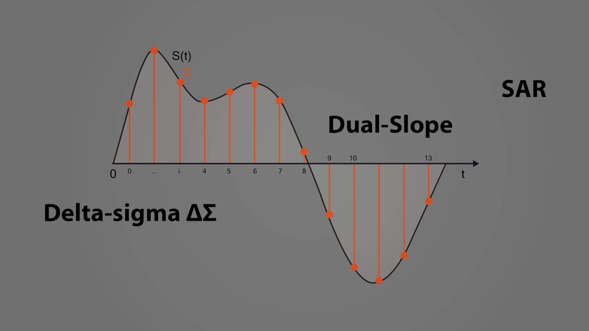
There are really five major types of ADCs in use today:
Successive Approximation (SAR) ADC
Delta-sigma (ΔΣ) ADC
Dual Slope ADC
Pipelined ADC
Flash ADC
Key ADC features and capabilities
Every technology has features and capabilities that drive its use in the market. With ADCs these include:
Sample rate - how fast can an ADC convert analog to digital?
Bit resolution - with how much precision can an ADC convert analog to digital?
Let’s look at each of these fundamental specifications in more detail:
What is the sample rate?
The rate at which the signals are converted from the analog domain to a stream of digital data is called the sample rate or sampling frequency. There is no right or wrong here, it simply depends on the application. For example, barometric pressure changes very slowly over a period of minutes or hours, so you really don’t need to sample it more than once per second. On the other hand, if you’re trying to measure a RADAR signature, you need to sample hundreds of millions of times per second, or perhaps even into the billions of samples per second.


In the world of data acquisition, we measure AC voltages and currents, shock and vibration, temperature, strain, pressure, and the like. These signals and sensors require sample rates in the range of DC to 200,000 samples per second (200 kS/s) on average, while a few applications require sampling up to 1,000,000 samples per second (1 MS/s).
The sample rate is usually referred to as the T (time) or X-axis of measurement.
Why is the sample rate important?
Understanding your signals and their highest possible frequencies is an important part of getting accurate measurements. For example, let’s say that we want to measure the output of an accelerometer.
If we expect it to experience vibrations with a maximum frequency of 100 Hz, we must set the sample rate to at least double that (the Nyquist frequency), but in practice ten times oversampling is better in order to get a good quality representation of the signal shape. So in this example, we set the sample rate to 1000 Hz and do the measurement.
Theoretically, everything should be fine, but how do we know that the signal didn’t really go much higher in frequency at a considerable amplitude? If it did, then our system would not accurately measure or convert the signal. And, in fact, if this is taken to an extreme, the measured values could even be completely wrong.
To understand aliasing, watch an old movie where a camera was filming at 24 frames per second as a wagon rolled by - at various speeds it can look like the wheels are spinning backward, or even not moving at all.
This is a kind of stroboscopic visual effect caused by the harmonic relationship between the rotational frequency of the wheel versus the picture-taking rate of the camera. Perhaps you’ve seen videos where a camera’s shutter speed was synchronized with a helicopter’s blades, where it appears that the helicopter is hanging in the air, its blades not moving at all.
In the case of a movie or an entertaining video it does not matter, but when making a scientific measurement, if we really believe that the wheels of a car are spinning backward, or that a helicopter’s blades are not moving, when in fact they are going quite fast, we have a real-world measurement problem.
In terms of digitizing voltage signals with our ADC, it is important that the sample rate is set appropriately. If we set it too high, we waste processing power and end up with data files that are unnecessarily large and hard to analyze. But if we set it too low, we could have two problems:
Missing vital dynamic signal components
Ending up with false (“alias”) signals (if the system lacks anti-aliasing filtering)

 in black, caused by sampling too infrequently compared to the original signal.")
Sample rate best practices
At this point, you might think to simply sample much faster than the signal could possibly reach, even orders of magnitude faster. Wouldn’t that solve the undersampling problem? Yes, but it would create a new problem: drastically increasing the amount of data recorded creates a data handling, storage, and analysis problem. And it may not even be possible to sample that fast with your system.
Luckily, there is a better way to avoid aliasing without overloading ourselves with vast amounts of mostly redundant data: anti-aliasing filtering.
Anti-aliasing filtering (AAF)
If we filter in the analog domain before the ADC, we can prevent the aliasing problem from ever occurring. Note that it is still important to set a high enough sample rate to capture the frequency range of interest, but at least with Anti-Aliasing Filters (AAF), we will avoid false signals from destroying the integrity of our measurements.
The ideal AAF would have a very flat passband AND a very sharp cutoff at the Nyquist frequency (essentially half of the sample rate).


Typical AAF configuration: a steep low-pass analog filter before the ADC prevents signals more than half of the maximum bandwidth of the ADC from passing. This is what Dewesoft does with its 16-bit SAR ADCs as found in SIRIUS-HS modules.
However, with their 24-bit Delta-sigma ADCs, Dewesoft systems have an additional DSP filter on the ADC itself that automatically adjusts based on the sample rate that the user has selected. This multi-stage approach provides the most robust anti-aliasing filtering available in DAQ systems today.
What is bit resolution and why does it matter?
While the sample rate as discussed in the previous section involves the time (T or X) axis of our digital data stream, bit resolution, or a number of bits involves the amplitude (Y) axis.
In the early days of data acquisition, 8-bit ADCs were common. As of this writing, in the world of DAQ systems, 24-bit ADCs are standard among most data acquisition systems designed to make dynamic measurements, and 16-bit ADCs are commonly considered the minimum resolution for signals in general. There are some low-end systems utilizing 12-bit ADCs.
Because each bit of resolution effectively doubles the possible resolution, systems with 24-bit ADCs provide 2^24 = 16,777,216. Thus, an incoming one-volt signal can be divided into more than 16 million steps on the Y-axis.
16,777,216 steps for a 24-bit ADC is dramatically better than the maximum theoretical 65,656 steps of a 16-bit ADC. Thus the appearance of waveshapes is accordingly more accurate and has a lot more precision, the more resolution you have. This applies to the time axis, too.

 vs. 16-bit resolution (gray)")
DualCoreADC® technology and why it matters
On the amplitude axis, one challenge that engineers have faced for years is the dynamic range. For example: what if we have a signal that is usually less than 5 volts, but at times can range upward dramatically? If we set the resolution of the ADC to accommodate the 0-5V data, the system will be totally overloaded when the signal rises past that.
One solution would be to use two channels set to different gains and refer to one of them for the 0-5V data, and to the other one for the higher amplitude data. But this is very inefficient - we can’t possibly use two channels for every input signal - we would need twice as many DAQ systems in order to do the same work. In addition, it would make data analysis after each test much more complex and time-consuming.
Dewesoft’s DualCoreADC® technology solves this problem by using two separate 24-bit ADCs per channel, automatically switching between them in real-time and creating a single, seamless channel. These two ADCs always measure the high and low gain of the input signal. This results in the full possible measuring range of the sensor and prevents the signal from being clipped.
With DualCoreADC® technology SIRIUS achieves more than 130 dB signal-to-noise ratio and more than 160 dB in dynamic range. This is 20 times better than typical 24-bit systems with 20 times less noise.
Multiplexed vs. single ADC per channel
Very often in lower-end DAQ systems, such as data loggers or industrial control systems, multiplexed A/D cards are used, because they are less expensive than A/D cards which have a separate ADC chip per input channel.
In a multiplexed ADC system, a single analog-to-digital converter is used to convert multiple signals from the analog to the digital domain. This is done by multiplexing the analog signals one at a time into the ADC.
This is a lower-cost approach, but it is not possible to precisely align the signals on the time axis, because only one signal can ever be converted at a time. Therefore, there is always a time skew between channels. If a small-time skew error is irrelevant in a given application, then it is not necessarily a bad thing. The same goes for the analog devices used within the system - choosing the best fit for the application in terms of form, fit, function, and avoiding obsolescence are driving factors.
In addition, since the maximum sample rate is always divided by the number of channels being sampled, the top sample rate per channel is usually lower in multiplexed systems, except in cases where only one or a few channels are sampled.
In today’s data acquisition systems, multiplexed ADC systems are employed primarily by low-end systems, where cost is more important than precision or speed.
Five main ADC technologies
There are five major types of ADCs in use today. Each has its place, based on its essential characteristics of bit resolution and sample rate. Let’s look at each of these types, see how they work, and how they are used in the world today.
Comparison of major ADC types
| ADC Type | Pros | Cons | Max Resolution | Max Sample Rate | Main Applications |
|---|---|---|---|---|---|
| Successive Approximation (SAR) | Good speed/resolution ratio | No inherent anti-aliasing protection | 18 bits | 10 MHz | Data Acquisition |
| Delta-sigma (ΔΣ) | High dynamic performance, inherent anti-aliasing protection | Hysteresis on unnatural signals | 32 bits | 1 MHz | Data Acquisition, Noise & Vibration, Audio |
| Dual Slope | Accurate, inexpensive | Low speed | 20 bits | 100 Hz | Voltmeters |
| Pipelined | Very fast | Limited resolution | 16 bits | 1 GHz | Oscilloscopes |
| Flash | Fastest | Low bit resolution | 12 bits | 10 GHz | Oscilloscopes |
Each has its own advantages and disadvantages and thus suitability for certain applications. Let’s look at each of them:
Successive approximation ADCs (SAR)
The “bread and butter” ADC of the DAQ world is the SAR analog-to-digital converter (Successive Approximation Register). It offers an excellent balance of speed and resolution and handles a wide variety of signals with excellent fidelity.
It’s been around for a long time, therefore SAR designs are stable and reliable, and the chips are relatively inexpensive. They can be configured for both low-end A/D cards, where a single ADC chip is “shared” by multiple input channels (multiplexed A/D boards), or in configurations where each input channel has its own ADC for true simultaneous sampling.


The analog input of most ADCs is 5V, which is why nearly all signal conditioning front-ends provide a conditioned output that is the same. The typical SAR ADC uses a sample-and-hold circuit that takes in the conditioned analog voltage from the signal conditioning front-end.
An onboard DAC creates an analog reference voltage equal to the digital code output of the sample and holds a circuit. Both of these are fed into a comparator which sends the result of the comparison to the SAR. This process continues for “n” successive times, with “n” being the bit resolution of the ADC itself, until the closest value to the actual signal is found.
SAR ADCs do not have any inherent anti-aliasing filtering (AAF), so unless this is added before the ADC by the DAQ system, if the engineer selects too low of a sample rate, false signals (aka “aliases”) will be digitized by the SAR ADC. Aliasing is particularly problematic because it is impossible to correct it after digitization.
There is no way to fix it with software. It must be prevented either by always sampling faster than the Nyquist frequency of all input signals or by filtering the signals before and within the ADC.
Pros
Simple circuit with only one comparator needed
Higher sample rates are possible compared to delta-sigma ADCs
Handles natural and unnatural waveshapes well
Cons
Anti-aliasing filtering must be added externally
Bit resolution and dynamic range limited compared to delta-sigma ADCs
Applications
Applications for SAR ADCs include DAQ systems, from low-end multiplexed ADC systems to higher speed single ADC per channel systems, industrial control and measurement, and CMOS imaging.
Delta-sigma ADCs (ΔΣ)
A newer ADC design is the delta-sigma ADC (or delta converter), which takes advantage of DSP technology in order to improve amplitude axis resolution and reduce the high-frequency quantization noise inherent in SAR designs.
The complex and powerful design of delta-sigma ADCs makes them ideal for dynamic applications that require as much amplitude axis resolution as possible. This is why they are commonly found in audio, sound, and vibration, and a wide range of high-end data acquisition applications. They are also used extensively in precision industrial measurement applications.


A low-pass filter implemented in a DSP eliminates virtually quantization noise, resulting in excellent signal-to-noise performance.
Delta-sigma ADCs work by over-sampling the signals far higher than the selected sample rate. The DSP then creates a high-resolution data stream from this over-sampled data at the rate that the user has selected. This over-sampling can be up to hundreds of times higher than the selected sample rate. This approach creates a very high-resolution data stream (24-bits is common) and has the advantage of allowing multistage anti-aliasing filtering (AAF), making it virtually impossible to digitize false signals. However, it does impose a kind of speed limit, so delta-sigma ADCs are typically not as fast as SAR ADCs, for example.
Pros
High-resolution output (24-bits)
Over-sampling reduces quantization noise
Inherent Anti-aliasing filtering
Cons
Limited to around 200 kS/s sample rate
Do not handle unnatural shape waveforms as well as SAR
Applications
Applications for Delta-sigma ADCs include data acquisition, especially noise and vibration, industrial balancing, torsional and rotational vibration, power quality monitoring, precision industrial measurements, audio and voiceband, and communications.
Dual slope ADCs
Dual slope ADCs are accurate but not terribly fast. The principal way they convert analog to digital values is by using an integrator. The voltage is input and allowed to “run up” for a period of time. Then a known voltage of the opposite polarity is applied and allowed to run back down to zero. When it reaches zero, the system calculates what the input voltage had been by comparing the run-up time with the run-down time, and by knowing what the reference had been. The run-up and run-down times are the two slopes for which this technique has been named.
This iterative process is reliable, but it takes time, and there is always a trade-off between resolution and speed because unlike SAR or delta-sigma ADCs, they cannot achieve both. As a result, Dual Slope aka “integrating ADCs” are used in applications like handheld multimeters and are not found in DAQ applications.


Pros
Very precise and accurate measurements
Cons
Slow conversion time due to the ramp-up and ramp-down iteration
Applications
Applications for dual slope ADCs include handheld and benchtop multimeters.
Flash ADCs
Flash ADCs are fast and operate virtually without latency, which is why they are the architecture of choice when the highest possible sample rates are needed. They convert analog to digital signals by comparing them with known reference values. The more known references that are used in the conversion process, the more accuracy can be achieved. For example, if we want a Flash ADC with a 10-bit resolution, we would need to compare the incoming analog signal against 1024 known values. The 8-bit resolution would require 256 known values, and so on.
The more resolution we want, the bigger and more power-hungry the Flash ADC becomes - and the sample rate has to be reduced.
For that reason, the 8-bit resolution is generally the “sweet spot” for these ADCs. Flash ADCs can operate into the low GS/s and still provide an 8-bit resolution.


Pros
Fastest ADC type
Instant conversion without latency
Cons
Circuit gets bigger and more power-consuming with each bit
The resolution effectively limited to 8-bit
Applications
Applications for Flash ADCs include the fastest digital oscilloscopes, microwave measurements, fiber optics, RADAR detection, and wideband radio.
Pipelined ADCs
For applications that require higher sample rates than SAR and delta-sigma ADCs can provide, but which do not require the ultra-high-speed of the Flash ADCs, we have Pipelined ADCs.
As discussed in the previous section, in a Flash ADC, the comparators are all latched simultaneously, hence the lack of latency. But this requires a lot of energy - especially when more and more comparators are used to achieve higher bit resolution. However, in a Pipelined ADC, the analog signal is not latched by all comparators at the same time, spreading out the energy required to convert the analog to a digital value.
Hence the flash comparators are “pipelined” into a quasi-serial process of 2-3 cycles. This has the benefit of allowing higher resolutions to be achieved without huge energy, but it imposes two penalties: sample rates cannot be as high as a pure Flash approach, and there is a latency of typically 3 cycles. This can be mitigated somewhat, but can never be completely eliminated.


These ADCs are a popular architecture for applications from 2-3 MS/s to 100 MS/s (1 GS/s is possible). For sample rates beyond this, Flash ADC technology is typically employed. The resolution of Pipelined ADCs can be as high as 16-bits at the lower sample rates but are typically 8-bits at the highest sample rates. Again, there is always a trade-off between speed and resolution.
Pros
Almost as fast as a pure Flash ADC type (faster than SAR and Delta-sigma)
Cons
Latency due to serial “pipelined” conversion process
Maximum sample rate limited by bit resolution
Applications
Applications for Pipelined ADCs include digital oscilloscopes, RADAR, software radios, spectrum analyzers, HD video, ultrasonic imaging, digital receivers, cable modems, and Ethernet.
Summary
Each ADC technology has its place. And because applications are so different, it is impossible to say one is better than another overall. However, it is absolutely possible to say one of them is better than another with respect to today’s DAQ applications requirements:
| Criterion | SAR ADCs | Sigma-Delta (ΔΣ) ADCs |
|---|---|---|
| When the best amplitude axis resolution is needed (even for slow signals like thermocouples!) | Normally 16 or 18 bits maximum | Better choice. 24-bit is the de facto standard among ΔΣ cards today. |
| When an inexpensive multiplexed AD card must be used | Only choice. It’s possible to MUX a single SAR ADC for multiple channels to create inexpensive DAQ systems when small-time skew errors are not an issue. | |
| When the highest possible sample rate is required | Better choice. There are SAR ADCs for data acquisition with up to 10 MS/s sampling. | On-board DSP processing makes ΔΣ ADCs their sample rates compared to SAR ADCs. |
| When AAF (anti-aliasing filtering) is desired | Expensive and complex to add to SAR ADCs | The better choice, since AAF is inherent to ΔΣ ADCs |
| When the highest signal-to-noise ratio is needed | The only choice. Possible to achieve up to 160dB with Dewesoft’s proprietary DualCoreADC® technology. | |
| When mostly unnatural signals will be recorded (such as square waves) | Better at representing square waves |
Although Dewesoft is famous for using 24-bit sigma-delta ADCs which have built-in anti-aliasing filters, they also use 16-bit SAR ADCs in order to achieve a 1 MS/s maximum sample rate in the SIRIUS DAQ systems product line. These SAR-based Dewesoft systems implement powerful AAF filtering in the form of 5th-order 100 kHz filters. There is an additional filter in the digital domain selectable among Bessel, Butterworth (or bypass), up to the 8th order.
The choice of which ADC technology to employ should always be based on application requirements. If you are measuring primarily static and quasi-static (slow) signals, you obviously don’t need a super-high-speed system, but you probably want one with as much amplitude axis resolution as possible.
Fixed systems used in the industry typically have requirements that do not change much, and it’s usually easier to choose a system.
For everyday DAQ systems, however, it’s a bit more challenging since these systems are used in a variety of applications over time. The key is to select one which has the best overall performance and protection against noise, aliasing, and obsolescence.
Read more:

