Table of contents
Browse categories
Browse authors
 AB
ABAlberto Boffi
 AL
ALAlessia Longo
 AH
AHAl Hoge
 AB
ABAljaž Blažun
 BJ
BJBernard Jerman
 BČ
BČBojan Čontala
 CF
CFCarsten Frederiksen
 CS
CSCarsten Stjernfelt
 DC
DCDaniel Colmenares
 DF
DFDino Florjančič
 EB
EBEmanuele Burgognoni
 EK
EKEva Kalšek
 FB
FBFranck Beranger
 GR
GRGabriele Ribichini
Glacier Chen
 GS
GSGrant Maloy Smith
 HB
HBHelmut Behmüller
 IB
IBIza Burnik
 JO
JOJaka Ogorevc
 JR
JRJake Rosenthal
 JS
JSJernej Sirk
 JM
JMJohn Miller
 KM
KMKarla Yera Morales
 KD
KDKayla Day
 KS
KSKonrad Schweiger
Leslie Wang
 LS
LSLoïc Siret
 LJ
LJLuka Jerman
 MB
MBMarco Behmer
 MR
MRMarco Ribichini
 ML
MLMatic Lebar
 MS
MSMatjaž Strniša
 ME
MEMatthew Engquist
 ME
MEMichael Elmerick
 NP
NPNicolas Phan
 OM
OMOwen Maginity
 PF
PFPatrick Fu
 PR
PRPrimož Rome
 RM
RMRok Mesar
 RS
RSRupert Schwarz
 SA
SASamuele Ardizio
 SK
SKSimon Kodrič
 SG
SGSøren Linnet Gjelstrup
 TH
THThorsten Hartleb
 TV
TVTirin Varghese
 UK
UKUrban Kuhar
Valentino Pagliara
 VS
VSVid Selič
 WK
WKWill Kooiker
Measuring Shock and Vibration with Accelerometer Sensors

September 29, 2025
In this article we will discuss how we can measure shock and vibration with accelerometer sensors, with enough detail so that you will:
See which accelerometers are available today
Learn the basic types of accelerometers available and how they are used
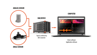
Understand how accelerometers can be interfaced with your DAQ system
Are you ready to get started? Let’s go!

Introduction
As human beings who grew up riding bicycles and pushing toys around the floor, we inherently understand an object’s acceleration due to an outside force. Vibration data and its derived parameters like acceleration, shock, and displacement are extremely important in so many applications.
What is vibration?
Vibration can be considered to be the oscillation or repetitive motion of an object around an equilibrium position, where the force acting on it is zero.
Vibration usually occurs because of the dynamic effects of manufacturing tolerances, clearances, rolling and rubbing contact between machine parts, and out-of-balance forces in rotating and reciprocating members. Often, small insignificant vibrations can excite the resonant frequencies of some other structural parts and be amplified into major vibration and noise sources. This is why monitoring vibration is so important.
The vibrating body describes an oscillating motion about a reference position. The number of times a complete motion cycle takes place during the period of one second is called the frequency and is measured in hertz (Hz).
The motion can consist of a single component occurring at a single frequency, as with a tuning fork, or of several components occurring at different frequencies simultaneously, as for example, with the piston motion of an internal combustion engine.
On the picture below we can see the motion of a tuning fork. A tuning fork is an acoustic resonator in the form of a two-pronged fork. It resonates at a specific constant pitch when set vibrating by striking it against a surface or with an object and emits a pure musical tone.
What is an accelerometer?
An accelerometer is a device that measures acceleration. The typical accelerometer acts like a damped mass that has been mounted on a spring. When exposed to acceleration, this mass moves. This displacement is measured and converted to useful units.
Accelerometers can be used to measure:
Vibration: an object is said to vibrate when it executes an oscillatory motion about a position of the equilibrium position. Vibration is found in the transportation and aerospace environments or as simulated by a shaker system.
Shock: a sudden transient excitation of a structure that generally excites the structure’s resonances.
Motion: the motion is a slow-moving event such as the movement of a robotic arm or an automotive suspension measurement.
Seismic: This is more of a motion or a low-frequency vibration. This measurement usually requires a specialized low noise–high-resolution accelerometer.
Force
Inclination
We can derive several important values from acceleration. For example, if we know the mass (m) of an object, we can multiply that by its acceleration (a) and thus derive the force (F):
Types of accelerometers
Although there are many types of accelerometers, utilizing different techniques and with very different specifications and applications among other factors, we can divide these sensors into two broad categories based on whether they can measure static acceleration or not:
AC accelerometers: Charge and IEPE accelerometers,
DC accelerometers: Capacitive, Piezoresistive, and MEMS accelerometers.
AC accelerometers
By definition, these sensors are used to measure dynamic events. In other words, they cannot measure DC, or static acceleration, but can only measure changes in acceleration.
Vibration is normally a high-frequency signal, requiring high-speed data acquisition. This is why a relatively low-speed datalogger is not used for these measurements. There are different technologies used within these sensors, each uniquely suited to an application and environment.
Piezoelectric accelerometers take advantage of the piezoelectric effect discovered by Pierre and Jacques Curie in 1880. They observed that certain materials, especially crystals and ceramic, would generate a charge or voltage in response to being stressed. They further saw that this response was linear with respect to the applied stress. The word “piezo” comes from the Greek word “piezein” which means “to squeeze.”
There are two popular types of AC accelerometer sensors available today:
Charge Accelerometer sensors
IEPE Accelerometer sensors
DC (and AC) accelerometers
The important thing is that DC accelerometers can accurately measure static (DC) acceleration. It is also important to note that DC accelerometers can also measure dynamic (AC) vibration, but do not normally have a high bandwidth of AC accelerometers. AC accelerometers have been specially designed for dynamic measurement applications.
Dynamic (AC) accelerometers cannot measure DC acceleration at all in most cases. But some of them have a settable time constant that allows DC acceleration to be measured for a short period of time.
There are several popular types of DC accelerometers available today:
Capacitive Accelerometers
Piezoresistive Accelerometers
MEMS Accelerometers
Please note that MEMS can refer to either Capacitive or Piezoresistive sensor technologies inside. But it’s important to have them listed here because they are referred to as a sensor type in the market.
Let’s look at each of these types of AC and DC accelerometers in detail.
Charge accelerometer sensors
In the classic charge sensor, the stress caused by acceleration on the axis of displacement generates a stream of charged ions that varies in intensity according to the amount of acceleration. Inside the sensor, a piece piezoelectric material (typically quartz or piezoelectric ceramic) is positioned beside a fixed mass. When the sensor housing is subjected to acceleration along the measuring axis, the stress or “squeezing” effect of the mass onto the piezoelectric material induces a charge output from the material. This electrical charge can be measured with a DAQ system.
Charge sensors have a high impedance output that requires a special charge mode signal conditioner, such as the SIRIUS CHG charge amplifier from Dewesoft.
Charge-type accelerometers have extremely high bandwidth, dynamic range, and very wide temperature operating ranges.
Charge sensors require special low-noise cabling because high-impedance charge signals are highly susceptible to RF (radio frequency) and EM (electromagnetic) interference. Moving cables induce noise onto the signal, so great care must be taken in cable routing (even the small pressure of cable ties can induce noise).
Charge sensor pros and cons
| Pros | Cons |
|---|---|
| No power supply is required | Requires an expensive signal conditioner |
| Durable and wide operating temperature range | Low-noise cables are required which are expensive |
| No noise | Limited to dynamic and quasi-static measurement applications |
| Highest resolution | It cannot measure the static acceleration |
| Excellent dynamic characteristics | |
| Extremely linear output | |
| High-temperature resistance (over 500°C) | |
| Very high shock amplitude range | |
| Smaller sensor design possible | |
Common charge accelerometer applications
Automotive testing
Aerospace and Defense testing
High bandwidth applications
Drop Testing
Free Fall Testing
Condition-based Monitoring
High-Temperature applications
IEPE accelerometer sensors
To get around this cabling and noise problem, engineers figured out how to integrate a tiny amplifier into the sensor housing itself. This amplifier converts the high-impedance output to a lower-impedance one which is easier to send over lower cost and longer-length cables.
It also dramatically reduces its susceptibility to RF and EM interference. These sensors are referred to as IEPE sensors, referring to the fact that they have integrated electronics. The acronym means “Integrated Electronics, PiezoElectric.”
Inside the sensor, a piece of piezoelectric material (typically quartz or piezoelectric ceramic) is positioned beside a fixed mass. When the sensor housing is subjected to acceleration along the measuring axis, the stress or “squeezing” effect of the mass onto the piezoelectric material induces a charge output from the material, which can be measured. This part is exactly the same as a charge sensor - the difference is that the IEPE sensor additionally includes a signal amplifier.
It should be noted that the company PCB Piezotronics also refers to these sensors using their proprietary acronym ICP®, which they define to mean “Integrated Circuit, Piezo-electric.” ICP is a registered trademark of PCB Group, Inc.).
Unlike charge sensors, which do not require external power, the tiny integrated amplifier within these IEPE sensors must be powered. Also, the amplifier’s mere presence within the sensor does add a small amount of mass, but more importantly, it lowers the sensor’s operating temperature range dramatically. Sensor power must be provided by an external IEPE signal conditioner, which creates a constant current supply on the signal line.
Since IEPE sensors are made for measuring dynamic and not static acceleration, this DC supply voltage has no effect on the readings. A signal conditioner made for IEPE sensors is typically less expensive than those made for CHARGE sensors. It is basically just a voltage conditioner that can supply a selectable constant current excitation to power the sensor.
IEPE accelerometers pros and cons
| Pros | Cons |
|---|---|
| Fixed sensitivity regardless of cable length and cable quality | Constant current excitation is required (reduces battery operating hours) |
| A higher output signal means less noise | The upper operating temperature range is limited to roughly 120°C |
| Longer cables are no problem | It cannot measure static signals |
| Requires a less expensive IEPE signal conditioner | Inherent noise source |
| Excellent dynamic response | |
| Low-impedance output can be transmitted over long cables | |
| Withstands better harsh conditions like dirt and humidity | |
| Intrinsic self-test function | |
Common IEPE accelerometer applications
Automotive testing
Aerospace and Defense testing
High bandwidth applications
Drop Testing
Free Fall Testing
Condition-based monitoring
Capacitive accelerometers
Capacitive accelerometers typically provide superior performance in the low-frequency range. Inside the sensor housing, two parallel plate capacitors are operated in differential mode. Two additional fixed-value capacitors are connected, and all four are connected as a full bridge.
These structures, arranged in close proximity within the sensor housing, generate small capacitances in the gaps between them when subjected to acceleration. The output of the bridge circuit varies linearly with this change in capacitance.
The accuracy of this sensor is improved by the use of interspersed “comb” tooth structures for detecting the capacitance. These can be arranged in several ways. These sensors can thus measure both dynamic (AC) and static (DC) acceleration.
Capacitive accelerometer pros and cons
| Pros | Cons |
|---|---|
| Can measure both AC and DC acceleration | Lack of high bandwidth of piezoelectric charge and IEPE sensors |
| Can be made very small and inexpensively (with somewhat limited accuracy) | Lack of high operating shock and temperature range of charge sensors in particular |
Common capacitive accelerometer applications
Capacitive accelerometers can be made quite small and inexpensively, and are therefore used across many commercial and consumer applications. Some of these include:
Cell phones, for orienting the screen “up” for the user, sudden deceleration or acceleration (crash detection)
Automobiles for the deployment of airbags,
Attitude detection of video game controllers,
Drones
And many more applications
Piezoresistive accelerometers
Another popular technology for DC accelerometers is based on piezoresistance. Instead of using crystal or ceramic elements as in piezoelectric sensors, piezoresistance accelerometers use strain gages to detect acceleration. This results in a sensor that can measure both static (DC) and dynamic (AC) acceleration up to roughly 6 to 8 kHz. Internal damping of the mass is done either fluid or gas.
The output of the typical piezoresistive accelerometer is differential, which is good in terms of noise performance. A good quality strain gauge signal conditioner is often required, e.g. SIRIUS STG type. Some of these sensors are designed to do well in high shock applications and can measure higher than 10.000 g.
Piezoresistive accelerometer pros and cons
| Pros | Cons |
|---|---|
| Well-suited to velocity and displacement applications because their DC outputs avoid integration and double integration errors better than AC output sensors | Not well suited for dynamic applications |
| Can measure down to 0 Hz | Limited temperature operating range due to internal electronics |
| Can measure a static angle | Upper bandwidth limited to low kHz range |
| Differential output | |
Common piezoresistive accelerometer applications
Automotive testing
Aerospace and Defense testing
High shock measurements
Non-dynamic shock and vibration measurements of all kinds
MEMS accelerometers
In addition to the mechanical accelerometers mentioned above, there are also electro-mechanical sensors (aka MEMS) available. Since CHARGE and IEPE sensors typically start to measure at 0.3 Hz to 10 Hz, they cannot make static or very low-frequency measurements. The Micro-Electro-Mechanical System sensor (MEMS) is a great solution.
MEMS accelerometers are available in both single and 3-axis versions.
MEMS accelerometer pros and cons
| Pros | Cons |
|---|---|
| Ideal for static/low-frequency measurements (can measure down to 0 Hz) | Limited temperature operating range due to internal electronics |
| Can measure a static angle | Upper bandwidth limited to low kHz range |
| Amplitude range limited to 400 g |
Common MEMS accelerometer applications
Seismic work
Structural monitoring
Gyro positioning systems
Automotive testing
Airbag testing
Accelerometer type comparison table
| Accelerometer Type | Pros | Cons |
|---|---|---|
| IEPE Accelerometers | Fixed sensitivity regardless of cable length and cable quality A higher output signal means less noise Longer cables are no problem Requires a less expensive IEPE signal conditioner in the measurement system Excellent dynamic response Low-impedance output can be transmitted over long cables Withstands better harsh conditions like dirt and humidity Intrinsic self-test function | Constant current excitation required (reduces battery operating hours) The upper operating temperature range is limited to roughly 120°C It cannot measure static signals Inherent noise source |
| Charge Accelerometers | No power supply is required Most durable and widest operating temperature range due to their simple design No noise, highest resolution Excellent dynamic characteristics Extremely linear output Able to withstand high-temperature environments (over 500°C) Very high shock amplitude range Smaller sensor design possible | They require a relatively expensive signal conditioner Susceptible to noise, so cable lengths must be short (< 10m) Low-noise cables required which are expensive Limited to dynamic and quasi-static measurement applications It cannot measure the static acceleration |
| Capacitive Accelerometers | Can measure both AC and DC acceleration Can be made very small and inexpensively (with somewhat limited accuracy) | Lack of high bandwidth of piezoelectric charge and IEPE sensors. Lack of high operating shock and temperature range of charge sensors in particular |
| Piezoresistive Accelerometers | Well-suited to velocity and displacement applications because their DC outputs avoid integration and double integration errors better than AC output sensors It can measure down to 0 Hz) It can measure a static angle Differential output | Not well suited for dynamic applications Limited temperature operating range due to internal electronics Upper bandwidth limited to low kHz range |
| MEMS Accelerometers | Ideal for static/low-frequency measurements It can measure a static angle | Limited temperature operating range due to internal electronics Upper bandwidth limited to low kHz range Amplitude range limited to 400 g |
Key considerations related to accelerometer sensor choice
There is a wide variety of sensors designed to measure vibration and shock. The most important questions you should ask yourself when choosing a sensor are:
Ground isolation
Sensitivity
Low-frequency range
Bandwidth
Amplitude range
Residual noise level
Temperature range
Weight
Ground loops
Cable noise
TEDS compatibility
Ground isolation
Very important when the object under test is conductive and at ground potential. A difference in ground voltage levels between the instrumentation and the accelerometer can cause a ground loop resulting in wrong data readings.
Sensitivity
Ideally, we would like a high output level, but high sensitivity normally requires a relatively large, heavy sensor. Luckily, this is not a critical problem because modern Dewesoft preamplifiers are designed to handle low-level signals.
Low-frequency range
The sensor must have a lower high-pass cutoff than the frequencies that you want to measure. For example, testing in a paper mill with frequencies of 1 to 5 Hz means you need a sensor with 0.3 Hz (or lower) bandwidth. For those applications, charge or IEPE are the most suitable. If you need to measure static acceleration, then a different sensor technology, such as capacitive or MEMS is needed.
Bandwidth (frequency range)
This is the (upper) bandwidth of the sensor. Small mass accelerometers can provide a resonant frequency up to 180 kHz, but for the somewhat larger, higher output, general-purpose accelerometers, resonant frequencies of 20 to 30 kHz are typical.
Amplitude range
Charge sensors provide large-amplitude ranges (specially designed shock sensors can have more than 100,000 g amplitude range!), but IEPE sensors are also fairly high (up to 1000 g). MEMS sensors usually have a very limited range (up to a few hundred g). For most applications, IEPE sensors are fine, whereas for high amplitude levels charge sensors are better.
Residual noise level
This defines the lowest amplitude level of what the sensor can measure. We should take a sensor with the optimum measurement range because sensors with a higher range will also have a higher noise level.
IEPE sensors have a very high dynamic range. Charge sensors are similar, but we need to consider that the noise can be easily generated in the cable. Capacitive and MEMS sensors provide a less dynamic range.
Temperature range
All the sensors, which include electronics, have a limited high-temperature range, up to 130°C. The temperature range of charge sensors is much higher - even up to 500°C. Please note however that this also requires a high-temperature cable.
All piezoelectric materials are temperature dependent so any change in the ambient temperature will result in a change in the sensitivity of the accelerometer. Piezoelectric accelerometers also exhibit a varying output when subjected to small temperature fluctuations, called temperature transients, in the measuring environment. This is normally only a problem when very low level or low-frequency vibrations are being measured.
Modern shear-type accelerometers have a very low sensitivity to temperature transients. When accelerometers are to be fixed to surfaces at higher temperatures than 250°C, a heat sink, and mica washer can be inserted between the base and the measuring surface. With surface temperatures of 350 to 400°C, the accelerometer base can be held below 250°C by this method. A stream of cooling the air can provide additional assistance.
MEMS sensor temperature range is limited by internal electronics (from -40°C to 125°C).
Weight
In modal testing, weight can be a big factor due to the mass loading effect. Any mass we add to the structure changes its dynamic behavior. As a general rule, sensor mass should be no more than one-tenth of the dynamic mass of the vibrating part onto which it is mounted.
And there are other considerations as well. such as cable noise, temperature range, transverse vibrations, etc. Entire textbooks have been written on this topic, including the mounting of these sensors, which is critical to getting good results. The important thing to know is that Dewesoft hardware and software have been designed from the ground up to help you get the best possible results from your vibration/acceleration testing.
There are many sensor types, and many models within each type from the manufacturers who make them. But we will focus on the main types which are used in the overwhelming number of applications around the world in this section.
Ground loops
The ground loop currents can flow in the shield of accelerometer cables because the accelerometer and measuring equipment is earthed separately. The ground loop is broken by using an isolated sensor, an isolated amplifier or electrically isolating the accelerometer base from the mounting surface by means of an isolating stud.
Cable noise
Cable noise is mainly the issue of the piezoelectric accelerometers because of the high output impedance. These disturbances can result from triboelectric noise or electromagnetic noise. Triboelectric noise is often induced into the accelerometer cable by the mechanical motion of the cable itself. It originates from local capacity and charge changes due to dynamic bending, compression, and tension of the layers making up the cable. This problem is avoided by using a proper graphitized accelerometer cable and taping or gluing it down as close to the accelerometer as possible.
Electromagnetic noise is often induced in the accelerometer cable when it is placed in the vicinity of running machinery.
TEDS compatibility
Some sensors have a TEDS chip inside them which allows them to be identified electronically by a compatible data acquisition instrument. TEDS (Transducer Electronic Data Sheet) is a standard interface according to IEEE 1451 and IEEE 1588. It stores important information about the device.
With compatible Dewesoft signal conditioners and Dewesoft X software, a TEDS sensor behaves in a “plug and play” fashion. The signal conditioner reads the information about the sensor and automatically sets up the proper gain, scaling, engineering units, and other sensor settings.
Engineers who use a lot of sensors find TEDS technology to be a huge time-saver when setting up a large-scale test. TEDS automation can also prevent human error.
Learn more about TEDS technology:
How to mount accelerometers
The sensors can be mounted in different ways. The bandwidth of the sensor is especially sensitive to the way it is mounted. The method of mounting an accelerometer to the measuring point is one of the most critical factors in obtaining accurate results from practical vibration measurements. Sloppy mounting results in a reduction in the mounted resonant frequency, which can severely limit the useful frequency range of the accelerometer.
Stud: it is best to drill a hole in the test specimen and fix the sensor to the surface with a screw. This should not affect any sensor property. Obviously, in some cases, a customer might not be particularly thrilled to do this, for example, to his brand new prototype of an aeroplane wing.
Adhesive: another type of mounting, which doesn't affect the bandwidth that much is a thin double-sided adhesive tape or beeswax (this is limited in its temperature range).
Magnet: a very widely used mounting technique for machine diagnostics is to mount the sensor on a magnet. This will still produce a good bandwidth, but of course, the surface must be ferromagnetic (not aluminium or plastic). On sensors where we can use the mounting clip, we can glue the mounting clip upfront and then just attach the sensor itself.
A quick and dirty solution is also to hold down the sensor with a hand on a rod. This is useful for some places which are hard to reach, but the bandwidth will be cut to 1 - 2 kHz.
The accelerometer should be mounted in a way that the desired measuring direction coincides with its main sensitivity axis. Accelerometers are also slightly sensitive to vibrations in the transverse direction, but this can normally be ignored as the transverse sensitivity is typically less than 1% of the main axis sensitivity.
The graph below is showing the bandwidth reduction from different mounting methods:
Accelerometer and vibration analysis applications
Some of the key vibration measurement applications of accelerometers are mentioned in the preceding sections. Here is a brief summary, plus some additional information.
| Test Type | Charge | IEPE | Capacitive | Resistive | MEMS |
|---|---|---|---|---|---|
| By Industry Domain | |||||
| Automotive Testing | √ | √ | √* | √ | √* |
| Aerospace and Military testing | √ | √ | √ | √* | |
| Drop Test | √ | √ | √ | ||
| Freefall Test | √ | √ | √ | ||
| Machine Condition Monitoring | √ | √ | √* | √* | |
| Consumer Products (cell phones, video games) | √ | √ | |||
| Drones | √ | √ | |||
| Gyro/positioning | √ | ||||
| Structural Testing | √ | √ | √ | ||
| Seismic Studies | √ | ||||
| By Performance Criteria | |||||
| High Temperature | √ | ||||
| High Bandwidth | √ | √ | |||
* Within their bandwidth
Below are just some of the typical vibration analysis applications that accelerometers are used for.
Order analysis
Order analysis is a tool to determine the operating condition of the rotating machines such as resonances, stable operation points, and determining a cause of vibrations.
The Dewesoft order tracking solution provides many powerful analytical capabilities:
Simultaneous time, frequency, and order domain measurement. This is made possible by the system’s high sample rate and advanced alias-free resampling techniques.
Angle sensor support. All angle sensors from tacho, encoder, gear tooth, gear tooth with missing or double teeth, tape sensors, and others are supported to perfectly determine the angle and rotational speed with 10 nanoseconds resolution using patented SuperCounter® technology
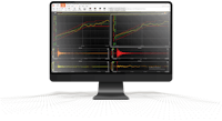
Rich visualization. As shown in the screenshot above, frequency and order 3D plots provide a great tool to determine machine health. Nyquist, Bode, and Campbell plots are available for data presentation. Orbit analysis with a raw or order view is ideal for turbomachinery analysis.
Advanced mathematics. Any order and time-domain harmonics can be easily extracted with amplitude and phase, available versus rotational speed or time in the run-up or coast-down modes.
Real-time calculations: Order tracking analysis solution provides real-time data acquisition, storing, visualization, and calculation on unlimited input channels. Multiple rotating types of machinery can be observed and analyzed at the same time.
Learn more:

Shock response spectrum (SRS) analysis solution
Mechanical shock pulses are often analyzed in terms of their shock response spectrum (SRS). SRS assumes that the shock pulse is applied as a base input to an array of independent single-degree-of-freedom (SDOF) systems. SDOF system assumes that each system has its own natural frequency.
ISO Standards support: The shock response spectrum is calculated according to the ISO 18431-4 standard for repeatability and compliance.
Fast setup: TEDS interface identifies and sets up sensors automatically, saving time, and eliminating human error.
Selectable frequency span: Freely definable calculation range for the frequency spectrum.
Damping quality factor: The selection of damping ratio or quality factor can be updated also in the offline mode, so engineers can apply different factors to the same data set for comparison purposes.
Advanced Mathematics: Relevant parameters such as composite/maximax, primary, residual, etc. are calculated in real-time. Results in the frequency domain spectrum can be shown as acceleration, velocity, or displacement.
Data export: Recorded data and calculated parameters can be exported in various standard data formats including Matlab®, Excel®, Diadem®, FlexPro®, UFF (Universal File Format), and others.
Learn more:
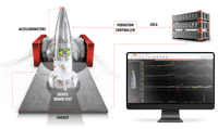
Sine reduction test - sine processing with COLA signal
Sine reduction test (also known as sine processing) synchronizes the data acquisition system seamlessly with a vibration shaker’s COLA (Constant Output Level Amplitude) signal. This allows the engineer to perform a deep evaluation of the structural properties of a large number of channels in real-time.
Real-time analysis. Real-time calculations of Peak, RMS, phase, THD on response points and obtain transfer functions between reference and response points on the entire structure simultaneously.
Unlimited Channel Count. Sine processing can be run on an unlimited number of channels while still maintaining all of the real-time capabilities.
Powerful Calculations. You can run true octave analysis in parallel with sine processing and FFTs simultaneously on all channels, in real-time. Additional math functions can be added from the extensive math library built into the software.
Online And Offline Animation. Test result quality can be determined by the animation of structure in all three directions with different projections during (and after) the measurement.
Easy Setup. TEDS technology detects and sets up sensors automatically within the software. Simply assign the channels to their location and start measuring quickly.
Advanced Storing Options. Automatic storing can be configured with trigger conditions, eliminating human error and ensuring consistent test results on expensive prototypes and unique structures.
Different Modes Of Frequency Detection. In addition to the well-known zero-crossing method of frequency detection, Dewesoft supports the Hilbert transform, enabling superior reading of frequency which results in smoother, more continuous data.
Easy Data Export And Reporting. Data can be exported to standard formats like UNV and Excel® for reporting purposes.
Learn more:
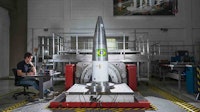
Octave analysis
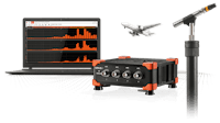
The octave analysis is an indispensable tool for sound measurement as well as predictive maintenance and monitoring due to its logarithmic frequency axis. In this case, microphones are used to capture sound. It is mentioned here because the octave analysis is often done in conjunction with tests also involving accelerometers, such as shock and vibration testing, and more.
Dewesoft's octave analysis solution meets all of the IEC and ANSI Class I specifications for octave filters.
Learn more:
FFT spectrum analyzer and frequency analyzer
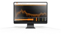
FFT spectrum analysis is an essential tool for engineers working in the shock and vibration domain. Looking deeper into the response of an object under test to frequency and amplitude stimuli is critical to system design and improvement.
Systems used for FFT and frequency analysis needs advanced cursor functions, high freely selectable line resolution, flexible averaging, and advanced functions for in-depth frequency analysis. The Dewesoft system provides all of this and more:
Real-time FFT Spectrum analysis. The Dewesoft spectrum analyzer offers real-time FFT analysis on unlimited input channels.
Unlimited Input Channels. DS DAQ systems have virtually unlimited input channel configurations. DEWESoft X software can perform FFT analysis on any or all of them at the same time.
Averaging. Overall (averaged) FFT with linear, peak, and exponential averaging or block-based calculation is available.
Capable of any Line Resolution. Selectable line resolution up to 64.000 lines for most demanding tasks.
Cursors and Markers. The FFT visual control can display values of the currently selected point with the markers. Available markers are a maximum marker, free marker, zoom marker, sideband marker, harmonic marker, RMS marker, delta marker, and more.
Cursor Value Estimate. The innovative window interpolation technique allows precise amplitude and frequency estimation.
Advanced Math. Auto spectrum, cross-spectrum, complex spectrum, waterfall spectrum, cepstrum (for bearing faults, speech processing), two-sided full FFT (for rotor whirl analysis), STFT (for non-stationary signals), envelope detection (for bearing fault analysis).
Learn more:
Rotational and torsional vibration analysis
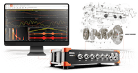
Torsional vibrations can be a source of failure on rotating shafts. When this happens, a whole system, whether it’s a factory production line that suddenly shuts down or an automotive or helicopter that suddenly loses propulsion, it can be costly and even catastrophic. This is why rotational and torsional vibration analysis is so critical.
The Dewesoft rotational and torsional vibration analysis module combined with the order tracking analysis module is a perfect tool for troubleshooting shafts, crankshafts, gears in automotive, industrial or power-generation applications.
Easy sensor setup. The DS mathematics module supports every type of sensor. The sensor type can be totally different for both ends of the rotor. Patented SuperCounter® technology provides 10ns resolution when determining rotational angle and speed.
Access to all measured data. All data, such as reference angle, individual sensor rotational angle, speed and acceleration, torsional angle, and velocity are available for advanced analysis.
Advanced mathematics. Different input filters and rotational DC filters are available as well. The engineer can enter custom rotational speed ratios for gearbox analysis.
Order Tracking Integration. Closely combined with order tracking, advanced data analysis is available based on the same angle sensors as the source of frequency.
Learn more:
Human and whole body vibration testing
The human body and whole-body vibration measure the effect of vibration on the human body. The extracted parameters allow the simple assessment of the injuries risk for workers, exposed to constant vibration.
The Dewesoft human body vibration solution supports the whole-body and hand-arm vibration measurement are supported according to all relevant international standards - ISO 5349, ISO 8041, ISO 2631-1, and ISO 2631-5.
Supported Standards. The Dewesoft solution calculates and measures whole/body vibration according to international standards ISO 5349, ISO 8041, ISO 2631-1, and ISO 2631-5.
Whole-body vibration. Applicable to motions transmitted from workplace machines and vehicles to the human body through a supporting surface.
Hand/Arm Vibration. Sensors are installed on special adapters for holding them on a handle or between fingers.
Advanced Mathematics. All data, such as RMS, Peak, Crest, VDV, MSDV, MTVV, Weighted raw, al(ISO 2631-5), D(ISO 2631-5) are available.
Data Analysis. Limitless combination with other standard tools of Dewesoft is a great base for R&D work related to the reduction of vibration due to its deep data analysis functionality.
Learn more:
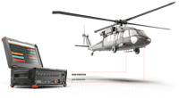

Balancing of rotating machines
Balanced rotors are essential for the smooth operation of rotating machinery. Unbalance will create high vibrations, reducing machine life and causing material defects.
Dewesoft's single- and dual-plane balancing solution works in both the static and dynamic modes. It is designed to help engineers eliminate unbalance on-site, reducing downtime, and saving money.
Learn more:
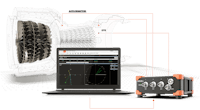
Modal analysis and modal testing - ODS, MIMO, OMA
Modal testing and modal analysis are s indispensable tools for determining the natural frequencies and mode shapes of structures. In these tests, a structure under test is “excited” with either an impact hammer or a modal vibration shaker, and the response is measured and analyzed.
Key testing methods supported by Dewesoft modal analysis include
ODS (Operating Deflection Shape)
MIMO (Multiple Input Multiple Output)
OMA (Operational Modal Analysis)
Engineers can Import standard geometry files, or draw their own, for real-time visualization and animation of the structure under test.
Impact Hammer mode allows grouping, rejecting, and repeating measurement points; multiple references and excitation points are supported. The ability to move excitation and response points is giving the user full flexibility when performing measurements.
Shaker Operation Mode. Working in combination with the in-built function generator module, the system allows any type of excitation from fixed sine with 1 MHz resolution, sweep sine, random, step sine, chirp, burst, and others.
Advanced Mathematics. Operating deflection shapes (ODS), mode indicator functions (MIF), and COLA analysis are fully implemented in Dewesoft while operational modal analysis (OMA) and time-domain ODS are available with close integration with an external software package.
Rich visualization. Animation of structure in all three directions and with different projections is available also during the measurement providing a great tool to determine the quality of results, giving the user a chance to repeat the measurement of any point. The modal circle tool determines exact resonance and calculates viscous or structural damping factors.
UNV Import/Export. Geometry can be either built via an in-built geometry editor or imported via the UNV file. All data, from the raw time domain to auto spectrums and FRFs can be exported using standard UNV file format.
Learn more:

Vibration shakers (vibration tables) for inducing vibrations
Accelerometers can be used to measure real-world vibrations, of course. But what if we want to test how an object reacts to various frequencies and amplitudes? Should we wait for years until every possibility has been seen from real-world experiences? Well, that’s not efficient, so engineers have invented vibration shakers to induce vibrations across a wide range of frequencies and vibrations.
Using a vibration shaker you can create anything from single-axis vibrations to multi-axis ones - you can set a fixed frequency and amplitude, or have them change or “sweep” up and down in order to test how an object under test reacts to countless vibration possibilities. Shakers are powerful tools for the shock and vibration testing world. Millions of accelerometers are affixed to objects under test and the shaker itself to model these results.
Dewesoft offers many solutions for a variety of tests involving shakers, such as Modal Analysis, SRS Shock Response Spectrum, Sine Reduction / Sine Processing Tests, and more. See the previous section for details.
Impact hammers for inducing shock
While a shaker is designed to excite a single frequency, impact hammers (aka modal hammers) are intended to excite a broad range of frequencies in an object under test. In a typical scenario, a structure is fitted with accelerometers at key locations. Then the operator strikes the structure at one or more locations with the impact hammer. The impact hammer has an accelerometer built into it which provides a known value to the measuring system, so we know exactly the force that was applied.
Impact hammers normally have interchangeable tips that can be attached to the impact head itself. Tips are made with different hardness levels, so we can strike the structure with various harnesses, from very soft and spongy to extremely hard and unforgiving. These impulses will excite the response of the structure in different ways, providing new insight into the structure.
You can learn more about Dewesoft modal testing with an impact hammer in this short video presentation:
Major accelerometer suppliers
This is not to include every single maker in the world, because there are hundreds of them. But there are several major suppliers of accelerometers that engineers are well familiar with:
| Company | Key Products | Website |
|---|---|---|
| Analog Devices | MEMS accelerometers | www.analog.com |
| Dytran Instruments | Charge, IEPE, and MEMS accelerometers | www.dytran.com |
| Endevco | Charge, IEPE and MEMS accelerometers | www.endevco.com |
| Kistler | Charge, IEPE, and MEMS accelerometers | www.kistler.com |
| Meggitt | Charge and MEMS accelerometers | www.meggitt.com |
| Omega Engineering | ACC series accelerometers | www.omega.com |
| PCB Piezotronics | IEPE accelerometers | www.pcb.com |
| Wilcoxon | IEPE accelerometers | www.wilcoxon.com |
| XSENS | MEMS accelerometers | www.xsens.com |
Compatible Dewesoft accelerometer signal conditioners
SIRIUS DAQ system family
SIRUS data acquisition systems offer high-end measurement modules for basically any type of accelerometer connection. There are several different modules available that are individually described below.
SIRIUS Dual-Core modules for accelerometers
High dynamic range DAQ modules with DualCoreADC technology and their compatibility with various accelerometers directly, and using DSI adapters.
Our DualCoreADC® technology boosts dual 24-bit delta-sigma ADC converters with an anti-aliasing filter on each channel. This allows our DAQ modules to achieve an astonishing 160 dB of dynamic range in the time and frequency domains. Along with up to 200 kS/s/ch sampling rate per channel, these are unique amplifiers on the market.
SIRIUS DualCoreADC® modules (up to 8 input channels per SIRIUS slice)
| SIRIUS-ACC | SIRIUS-CHG | SIRIUS-STG SIRIUS-STGM | SIRIUS-LV | |
|---|---|---|---|---|
| Charge Accelerometers | N/A | Directly supported | Supported via DSI-CHG | Supported via DSI-CHG |
| IEPE Accelerometers | Directly supported | Directly supported | Supported via DSI-ACC | Supported via DSI-ACC |
| Capacitive Accelerometers | Supported(requires external power supply) | N/A | Directly Supported | Supported(requires external power supply) |
| Piezoresistive Accelerometers | N/A | N/A | Directly Supported | N/A |
| MEMS sensors with analog output | Supported(requires external power supply) | N/A | Directly Supported | Directly Supported |
SIRUS HD - high-density modules for accelerometers
High-density SIRIUS module with up to 16 channels per SIRIUS slice is the perfect choice for high-channel count applications.
SIRIUS HD (High Density) modules (up to 16 input channels per SIRIUS slice)
| SIRIUS-HD-ACC | SIRIUS-HD-STGS | SIRIUS-HD-LV | |
|---|---|---|---|
| Charge Accelerometers | N/A | Supported via DSI-CHG | Supported via DSI-CHG |
| IEPE Accelerometers | Directly supported | Supported via DSI-ACC | Supported via DSI-ACC |
| Capacitive Accelerometers | Supported(requires external power supply) | Directly Supported | Directly Supported |
| Piezoresistive Accelerometers | N/A | Directly Supported | N/A |
| MEMS sensors with analog output | Supported(requires external power supply) | Directly Supported | Directly Supported |
SIRUS HS - high-speed modules for accelerometers
1 MHz 16-bit SAR technology with software-selectable alias-free filtering is the perfect choice for transient recording. Up to 8 channels per SIRIUS module.
SIRIUS HS (High Speed) modules (up to 8 input channels per SIRIUS slice)
| SIRIUS-HS-ACC | SIRIUS-HS-CHG | SIRIUS-HS-STG | SIRIUS-HS-LV | |
|---|---|---|---|---|
| Charge Accelerometers | N/A | Directly supported | Supported via DSI-ACC | Supported via DSI-ACC |
| IEPE Accelerometers | Directly supported | Directly supported | Supported via DSI-CHG | Supported via DSI-CHG |
| Capacitive Accelerometers | Supported(requires external power supply) | N/A | Directly Supported | Directly Supported |
| Piezoresistive Accelerometers | N/A | N/A | Directly Supported | N/A |
| MEMS sensors with analog output | Supported(requires external power supply) | N/A | Directly Supported | Directly Supported |
SIRIUS MINI for IEPE accelerometers
The SIRIUS MINI is a small and highly portable USB-powered data acquisition system ideal for acoustic, vibration, and rotating machinery analysis. It has four high-speed/high-resolution input channels made specifically for the IEPE accelerometer sensors. The inputs can also be used as plain voltage inputs (software selectable), so you could also use charge sensors if you have separate charge amplifiers, as well as piezoresistive or capacitive sensors if you have external signal conditioning for them.
SIRIUS MINI does not require any external power supply. It can be powered straight from the USB connection, for example, a laptop. It is pre-configured with four high dynamic analog inputs, each of which features dual sigma-delta ADCs with 200 kHz per channel sampling rate and up to 160 dB dynamic range. It can also include one counter/encoder input that is capable of handling either three digital inputs OR one event counter, encoder, period, pulse-width, or duty-cycle counter input.
| SIRIUS MINI | |
|---|---|
| Charge Accelerometers | N/A |
| IEPE Accelerometers | Directly supported |
| Capacitive Accelerometers | Supported (requires external power supply) |
| Piezoresistive Accelerometers | N/A |
| MEMS sensors with analog output | Supported (requires external power supply) |
DEWE-43A and MINITAURs modules for accelerometers
The DEWE-43A DAQ system is an extremely portable, handheld DAQ system. Connecting to your computer via a locking USB connector, it features eight universal analog inputs. It’s “big brother” is called the MINITAURs - this is essentially the DEWE-43A combined with a computer and a few other features, in a single highly portable enclosure. The universal inputs of both systems are compatible with Dewesoft’s DSI adapters, allowing you to connect an RTD sensor to any or all of their eight input channels.
Both models have differential universal inputs, which are basically full-bridge / low voltage modules that are compatible with DSI series adapters, which are available for both charge and IEPE accelerometer sensors. DSI adapters use TEDS to automatically configure themselves in Dewesoft X DAQ software. Simply plug the DSI adapter into the selected input’s DB9 input, verify your settings on the hardware setup screen in Dewesoft X software, and you’re ready to start making measurements.
| DEWE-43A | MINITAURs | |
|---|---|---|
| Charge Accelerometers | Supported using DSI-CHG | Supported using DSI-CHG |
| IEPE Accelerometers | Supported using DSI-ACC | Supported using DSI-ACC |
| Capacitive Accelerometers | Supported | Supported |
| Piezoresistive Accelerometers | Supported | Supported |
| MEMS sensors with analog output | Supported | Supported |
KRYPTON multi-channel modules for accelerometers
KRYPTON is the most ruggedized range of products available from Dewesoft. Built to withstand extreme temperature and shock and vibration conditions, KRYPTON DAQ modules are rated to IP67, protecting them against water, dust, and more. They connect to any Windows computer (including Dewesoft’s own ruggedized IP67 KRYPTON CPU model) via EtherCAT and can be separated by up to 100 meters (328 feet), allowing you to locate them near the signal source. Like SIRIUS, they run the most powerful Dewesoft X DAQ software on the market.
KRYPTON multi-channel modules
| ACC (4 or 8 channels) | STG (3 or 6 channels) | LV (4 or 8 channels) | |
|---|---|---|---|
| Charge Accelerometers | N/A | Supported via DSI-CHG | Supported via DSI-CHG |
| IEPE Accelerometers | Directly supported | Supported via DSI-ACC | Supported via DSI-ACC |
| Capacitive Accelerometers | Supported(requires external power supply) | Directly Supported | Directly Supported |
| Piezoresistive Accelerometers | N/A | Directly Supported | N/A |
| MEMS sensors with analog output | Supported(requires external power supply) | Directly Supported | Directly Supported |
KRYPTON ONE single-channel modules for accelerometers
Single-channel voltage input ruggedized modules for the ultimate in modularity.
KRYPTON ONE single-channel modules
| ACC | STG | LV | |
|---|---|---|---|
| Charge Accelerometers | N/A | Supported via DSI-CHG | N/A |
| IEPE Accelerometers | Directly supported | Supported via DSI-ACC | N/A |
| Capacitive Accelerometers | Supported(requires external power supply) | Directly Supported | Supported(requires external power supply) |
| Piezoresistive Accelerometers | N/A | Directly Supported | N/A |
| MEMS sensors with analog output | Supported(requires external power supply) | Directly Supported | Supported(requires external power supply) |
IOLITE modules for accelerometers
IOLITE DAQ and control system is a unique product that combines the essential capabilities of a real-time industrial control system with a powerful DAQ system. With IOLITE, hundreds of analog and digital channels can be recorded at full speed while simultaneously sending real-time data to any third-party EtherCAT master controller.
IOLITE modules
| IOLITE-8xLV (8 channels) | IOLITE-6xSTG (6 channels) | |
|---|---|---|
| Charge Accelerometers | N/A | Supported via DSI-CHG |
| IEPE Accelerometers | N/A | Supported via DSI-ACC |
| Capacitive Accelerometers | Supported(requires external power supply) | Directly Supported |
| Piezoresistive Accelerometers | N/A | Directly Supported |
| MEMS sensors with analog output | Supported(requires external power supply) | Directly Supported |
Dewesoft branded accelerometer sensors
Dewesoft offers a variety of popular accelerometers that are perfectly suited to Dewesoft hardware and software. These accelerometers are equipped with a TEDS smart sensor interface that allows Dewesoft X DAQ software to automatically detect the sensor and set the correct scaling, eliminating human error and making the system set up fast and easy. All Dewesoft vibration sensors are fully compatible with the Dewesoft vibration shaker line.
Vibration sensors
For standard measurements or modal analysis single axis, model I1T-50G-1 and isolated triaxial model I3T-50G-1 IEPE cube accelerometer with 50 g range are recommended. Model I1AI-500G-1 is a miniature accelerometer intended for the measurement of higher vibrations up to 500g.
Dewesoft industrial accelerometers
Case-isolated sensors can also be used with non-isolated amplifiers without worrying about ground loops. The I1TI-50G-2 IEPE sensor is perfect for industrial applications due to its rugged case and connector. I3TI-50G-1 is a standard triaxial sensor with a 50 g range. I1TI-500G-1 is a single-axis accelerometer that can measure up to 500 g. The C1T-50g-1 charge accelerometer can be used in high-temperature environments up to 190° C.
All Dewesoft vibration sensors are fully compatible with the Dewesoft vibration shaker line.
Modal impact hammer
Complementary to vibration sensors, the IH-441N-1 modal hammer with up to 440 N range is a perfect fit for modal analysis applications using Dewesoft software. Our modal hammer is equipped with a TEDS smart sensor interface. Dewesoft X software automatically detects the sensor and sets the correct scaling.
Check other articles in the sensor series:
