


Measuring Position and Displacement With LVDT Sensors

August 12, 2020
In this article we will discuss how you can measure position and displacement with LVDT sensors, with enough detail so that you will:
See how these sensors work
Learn how LVDT sensors can be used to measure the distance
Understand how you can use them in your testing
Are you ready to get started? Let’s go!
What is the LVDT sensor?
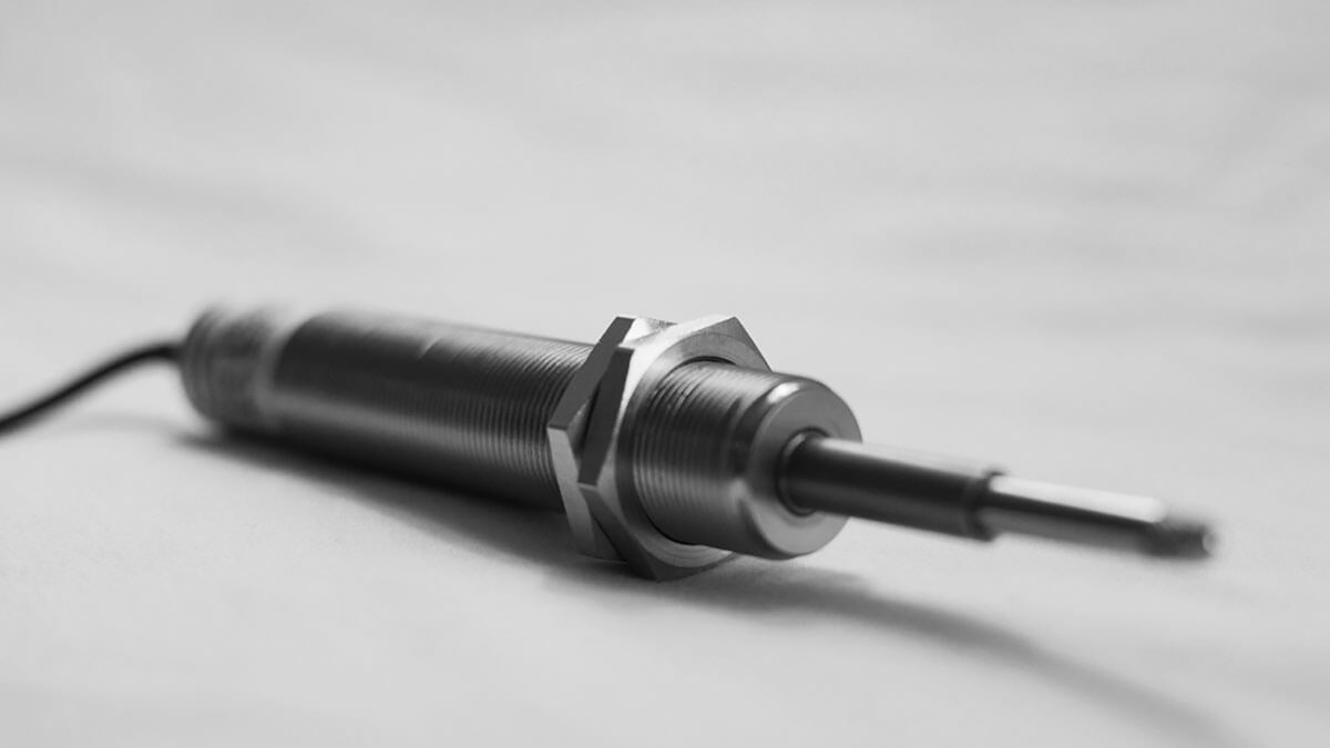
LVDTs (Linear Variable Differential Transformers) are linear position sensors. They are used to measure linear displacement and position over relatively short distances. There are LVDTs on the market today that can measure movements as small as several millionths of a cm (microinches) or even up to about 0.7 meters (~27 inches) at the other extreme.
An LVDT consists of a tube that contains a freely moving shaft (aka armature). The base of the tube is mounted to a fixed position, and the end of the rod is affixed to an object whose position will be moving in a linear (back and forth) fashion.


How does an LVDT sensor work?
Inside the LVDT’s housing is the primary coil. On either side of the coil assembly is a pair of secondary coils. Except for their physical positions, all three primary windings are identical. However, they are wired in series with the opposition, so that if they are energized equally, their outputs will add up to zero.
Note that these internal elements are normally constructed in such a way that they are protected against both moisture and external magnetic fields.


In an AC LVDT, the primary coil is energized with a constant AC supply voltage, typically 3 kHz @ 3Vrms. This induces a field in the secondary coils. If the rod is a dead centre within the tube, the magnetic flux from S1 and S2 are identical and cancel each other out. This is known as the “null” position.
However, if the shaft’s position moves closer to either S1 or S2, the energy from that coil will increase relative to the other coil. So by simply subtracting the outputs from the coils, the sensor tells us where the shaft is positioned within the tube at all times.


As the shaft is pulled in or out of the tube by the test article, the LVDT outputs a signal that represents the position of the shaft from its starting point to its maximum deflection. The shaft does not touch the inside of the tube, making it virtually frictionless, and the LVDT itself contains no electronics, making it popular in harsh environments.
This signal is output to an LVDT signal conditioner within a measuring system, which displays it and records it for review and analysis.
To summarize, an AC LVDT is a variable-reluctance device whose primary coil creates a magnetic flux that is coupled through a moving armature to secondary coils wired in series opposition to the primary.
LVDT types or mechanical varieties
In terms of their shaft/armature construction there are several basic varieties available today:
Free (Unguided) Armature LVDTs
Captive (Guided) Armature LVDTs
Forced or Spring-extended Armature LVDTs
Let’s look at each of these in more detail.
Free (unguided) armature LVDTs
In this case, the shaft or armature is free to slide back and forth in the LVDT body. It is not fastened to it, nor does it have any force acting on it within the LVDT itself. The armature is connected to the object under test, which moves in parallel with the LVDT body.
The result is a virtually frictionless arrangement, resulting in a very long life span for the sensor. Of course, proper alignment is required to achieve the best results.
A free or “unguided” armature is ideal for short-range, high-speed applications (e.g., vibration). It is also ideal when a high number of cycles will be observed. It works best when the object under test is moving in parallel with the LVDT body.
Captive (guided) armature LVDTs
In a captive or guided LVDT, the armature is connected both to the body and the object under test. The armature is guided by a low-friction bearing assembly that restrains it.
This allows the LVDT to handle longer measurement ranges (e.g., ~25 mm to 45 cm [~0.5 to 18 in.]), as well as scenarios when the object under test is moving transversely to the LVDT body. In these cases, misalignment would occur if the armature were not guided.
Captive (guided) armature LVDTs are useful in both static and dynamic measurement applications.
LVDTs with short ranges (e.g., maximum ±76 mm [±3 in.]) can be mounted horizontally and will not flex, however, larger units normally need to be supported when mounted horizontally to ensure that they are not bent by gravity.
Check out Dewesoft's modern, digital EtherCAT data acquisition and control systems that are fully compatible and ready for LVDT measurement


Forced or spring-extended armature LVDTs
A forced or “spring-extended” armature LVDT has the same low-friction bearing assembly of a captive (guided) LVDT as described above, but in addition, it uses a mechanical return mechanism like a spring, pneumatics, or a motor to lightly push the armature out to its full deflection. This is for applications where it is desired that the LVDT armature maintain a steady connection with the object under test.
In this scenario, only the LVDT body is fixed, and the armature end typically has a ball on its end that pushes against the object under test and is not fastened to it. So the object under test can even move out of reach or be replaced with a different object as in the case of an assembly line. The spring-extended armature ball will extend automatically and wait for the object to return or be replaced, and move with it smoothly when it does.
These LVDTs are best for static and slow-moving applications.
Most LVDT manufacturers make their sensors available in some or all of these armature varieties, in order to handle a wide range of applications.
There is a wide variety of LVDTs on the market today. Some are designed specifically for applications and environments such as hygienic applications with food and medicines, for submersion in saltwater, in extreme temperature environments, for very high precision applications in science, and even counting money, within pressurized environments, and many more variants. They are often constructed of stainless steel, making them well suited for these applications.
AC vs DC LVDTs
The classic AC LVDT has NO electronics on board and requires an external carrier amplifier and related signal conditioning to work. Some manufacturers have integrated these electronics into LVDTs. These DC LVDTs are easier to interface with measuring systems, of course, but there are some restrictions.
Because AC LVDTs have no onboard electronics, they can operate in the widest possible temperature environments - from cryogenic all the way up to 650°C / 1200° F.
AC LVDTs can also be smaller than DC LVDTs due to the lack of electronics.
AC LVDTs have superior shock and vibration specifications than DC LVDTs due to their lack of electronic components.
AC LVDTs have a longer lifespan than DC LVDTs … less complexity means more reliability.
This does not mean that there is no purpose for DC LVDTS. There are plenty of applications for which their easier interface is a big advantage, and where the advantages of AC LVDTs are not a factor. They eliminate the need for external signal conditioning, for one thing, which can sometimes be a hard requirement when there is no suitable location for it.
They also reduce installation time and complexity. DC LVDTs are available in loop-powered models, whose 4-20 mA current outputs can be transmitted over a longer distance than low-level voltage outputs.
| AC LVDT Advantages | DC LVDT Advantages |
|---|---|
| Best shock and vibration performance | Does not require external signal conditioning |
| Widest temperature operating range | Outputs are pre-calibrated |
| Smallest possible form factors are available | Reduced set-up time |
| Longest possible lifespan design | 4-20 mA current loop output available for long-distance transmission |
LVDT measurement applications
Machine tools
Tensile test stands
Aerospace test - landing gear, actuators, control surface positioning, hydraulics
Automotive and Train tests - movements of suspension systems
Power generation - turbine testing
Robotics - position feedback
Manufacturing - Automation, process controls
Pulp & Paper - tensioning arms positioning
LVDT sensor pros
Very reliable - long sensor lifespan due to near frictionless operation of most models
Very high resolution - because of the near-frictionless movement they provide virtually infinite resolution. Even the smallest changes can be detected.
Damage resistant - in some models, both ends of the tube are open, preventing sensor damage if the test article pushes the rod farther than expected (except for collision with the tube itself)
Null point stability - the zero or null point of the sensor is extremely repeatable due to the construction of the sensor itself
Wide range of operating temperatures - there are LVDT models available that can withstand cryogenic temperatures (-200° C / -328° F) as well as high temperatures (650°C / 1200° F)
Low hysteresis / high positional accuracy and repeatability
Absolute reading output device - as opposed to an incremental output device, the reading from an LVDT will be the same before and after its power is cycled (assuming that the object under test did not move).
LVDT sensor cons
Limited measurement distance - Even the largest LVDTs are limited to less than 1 m (~27”) measurement ranges
Can be affected by magnetic fields (models with shielding are common as a result)
AC models require a precise AC excitation from an LVDT signal conditioner
DC LVDT models have inferior shock, vibration and temperature specifications compared to AC LVDT models
Connecting AC LVDT sensors to your Dewesoft DAQ system
Signal conditioning is always needed with AC LVDT sensors because of their AC excitation requirement. DC LVDT sensors require either a voltage or a 4-20 mA current input. Using a DSI-LVDT adapter it is possible to connect LVDT sensors to STG and LV Dewesoft DAQ signal conditioners, across several different models.
The section that follows shows which inputs on which DAQ system models are compatible, but first let’s look at the DSI adapters in general, and then the single-channel DSI-LVDT adapter and DS-16xLVDTr 16-channel interfaces specifically.

DSI LVDT adapters - a closer look
DSI adapters are compatible with all Dewesoft STG and LV signal conditioners which are available with DB9 analog input, regardless of the product family. They will fit the SIRIUS DAQ system, KRYPTON DAQ modules, IOLITE and IOLITE modular DAQ and control system, DEWE-43A, and MINITAURs DAQ systems.


All DSI adapters have a TEDS chip built-in for automatic sensor detection and plug-and-play setup. Just connect the DSI adapter to a compatible input and everything -- including the scaling, units, calibration data, etc. -- will be configured automatically inside the DewesoftX DAQ software. All electronics are built into small and rugged aluminium housing with screw connectors to firmly fix these adapters to the analog input channel.

The DSI-LVDT adapter


The DSI-LVDT is an adapter for connecting LVDT sensors to your Dewesoft DAQ system. It generates the 4 to 10 kHz AC excitation that LVDT sensors require, and includes easy phase adjustment via a small built-in potentiometer. The output 1 V = 1000 mV / V.
The DS-16xLVDTr
The DS-16xLVDTr combines 16 channels of DSI-LVDT adapters in a 19”-rack compatible housing with 1U height.


The breakthrough of this new design is the asynchronous excitation input/outputs. You connect an excitation signal from an external function generator to the “IN” BNC connector. This excitation signal is automatically routed to the “OUT” BNC connector, which you can use to daisy chain to additional DS-16xLVDTr interfaces for large channel count LVDT measurement systems.
There are 16 x DB9 (male) connectors on the front panel for the connection to the Dewesoft data acquisition system. Each connector includes a trimmer for phase adjustment.
On the back panel are 16 x DB9 (female) connectors for the LVDT sensor connection. DS-16xLVDTr supports measurements with full-bridge and half-bridge LVDT sensor types.
SIRIUS DAQ systems LVDT compatibility


The SIRIUS line includes not just the SIRIUS module or “slice” itself but is a whole product line including SIRIUS, SIRIUS waterproof, SIRIUS R1DB, SIRIUS R2DB, SIRIUS R3, SIRIUS R4, and SIRIUS R8. The following SIRIUS signal conditioners are compatible with LVDT measurements:
SIRIUS standard input modules
| Module | STG | STGM | LV (DB9) |
|---|---|---|---|
| DSI-LVDT compatible | √ | √ | √ |
| DS-16xLVDTr compatible | √ | √ | √ |
SIRIUS HD (high-density) input modules
| Module | HD-STGs | HD-LV (DB9) |
|---|---|---|
| DSI-LVDT compatible | √ | √ |
| DS-16xLVDTr compatible | √ | √ |
SIRIUS HS (high speed) input modules
| Module | HS-STG | HS-LV (DB9) |
|---|---|---|
| DSI-LVDT compatible | √ | √ |
| DS-16xLVDTr compatible | √ |
DEWE-43A and MINITAURs product family LVDT compatibility


The DEWE-43A is a handheld 8-channel DAQ module that provides eight universal analog inputs with DB9 connectors. The MINITAURs is essentially a DEWE-43A combined with a rugged computer, so its inputs are exactly the same.
DEWE-43A and MINITAURs 8 x universal inputs
| Module | Compatibility |
|---|---|
| DSI-LVDT compatible | √ |
| DS-16xLVDTr compatible | √ |
KRYPTON DAQ modules LVDT compatibility

 systems")
KRYPTON and KRYPTON ONE are extremely rugged DAQ modules, rated to IP67 for operating in harsh environments with shock, vibration, and high and low-temperature extremes. Every Dewesoft DAQ system includes award-winning DewesoftX software for complete system setup, operation, display, storage, analysis, and report generation. The input modules shown below are compatible with the DSI-LVDT adapter:
KRYPTON rugged multi-channel modules
| Module | STG-3 | STG-6 |
|---|---|---|
| DSI-LVDT compatible? | √ | √ |
| DS-16xLVDTr compatible? | √ | √ |
KRYPTON-1 rugged single-channel modules
| Module | STG-1 |
|---|---|
| DSI-LVDT compatible? | √ |
| DS-16xLVDTr compatible? | N/A |
IOLITE product family LVDT compatibility


IOLITE and IOLITE modular DAQ and control system combines powerful data acquisition with real-time control via dual EtherCAT interfaces. Available in a 19” rack model as well as a benchtop model. Every Dewesoft DAQ system includes award-winning DewesoftX software for complete system setup, operation, display, storage, analysis, and report generation. The six-channel strain gage module is compatible with DSI adapters, including the DSI-LVDT:
IOLITE digital I/O modules
| Module | 6xSTG |
|---|---|
| DSI-LVDT compatible | √ |
| DS-16xLVDTr compatible | √ |
Conclusion
LVDTs are extremely useful sensors. They are highly reliable and accurate and easy to use. As a result, there are many millions of them in use all around the globe performing countless measurement and control applications.
Every member of the Dewesoft DAQ product family is compatible with LVDTS by way of easy-to-use DSI-LVDT adapters and the 16-channel DS-16xLVDTr interface... You can enhance your test, measurement, and control applications utilizing Dewesoft DAQ hardware and its accompanying software with LVDT sensors.
Check out Dewesoft's modern, digital EtherCAT data acquisition and control systems that are fully compatible and ready for LVDT measurement