


Measuring RPM, Angle, and Speed Using Digital, Encoder and Counter Sensors

May 5, 2020
In this article, we will discuss how you can measure digital signals as well as digital encoders, tachometers, and RPM sensors with today’s best data acquisition (DAQ) systems, with enough detail so that you will:
See how these sensors work
Learn how digital sensors are synchronized with analog data
Understand how you can use them in your testing
Are you ready to get started? Let’s go!
Introduction
Most engineers understand that data acquisition systems are used to measure time-history signals, such as voltages, temperatures, currents, vibrations sensed by accelerometers, strain sensed by Wheatstone bridge strain gauge sensors, and more.
But often it is necessary to measure discrete events and angle of rotation signals which are synchronous with the more common time-history data. Discrete events are those events that have only two possible values, e.g. on / off switches, etc.
These are sometimes called “digital signals” since they are fundamentally composed of high-low (aka “on/off”) voltage states. In the sections that follow, we will present some examples of these additional signal types, and discuss how they are best measured and synchronized with the rest of the data.
What are discrete signals/digital signals?
Let’s take the case of a proximity switch or sensor, which outputs a low voltage (0 V in this example) when the unit under test (UUT) is not nearby, but then outputs a higher voltage (5V) when the UUT comes within range. It may be necessary to record this discrete state in sync with our measuring system in order to put the analog data into context. So how can we do it?


One simple way is to take these electrical signals and input them into the analog inputs of the measuring system. This will work and only occupies one analog channel. However, what if we needed to record the states of eight proximity sensors … or ten … or more?
In that case, it would be an enormous waste of our wide-ranging and relatively expensive analog inputs to use them for such simple discrete signals. In addition, sometimes discrete inputs require higher bandwidth than the relatively slow analog inputs can support, so again an analog input may not be a good fit regardless.
When multiple discrete signals need to be acquired, it is more efficient and far less expensive to use a digital input that is designed for this task. In the case of Dewesoft DAQ systems such as the SIRIUS product line, each counter input can handle a variety of sensors with discrete digital outputs such as counters and encoders, as well as a number of discrete digital inputs.
And since counter/encoders typically run at a very high rate, the timebase of these inputs is quite high at 102.4 MHz, which provides a 10 MHz bandwidth - far in excess of typical analog inputs for physical measurement.
The simplest of digital inputs is the on/off type of signal that looks like a square wave if you look at it. These are sometimes referred to as “discrete channels” or “event channels.” Since they have only two states, they are often used to show the state of a door being open or closed, a circuit being on or off, or a blade passing by, and a thousand other yes/no possibilities that we might need to measure.
What is a TTL signal?
Discrete inputs are normally output from a relay or transducer at TTL (transistor to transistor logic) levels, which are based on a 5V pull-up. In theory, the perfect TTL on/off signal would be 0V representing OFF (meaning a digital value of 0), and 5V representing ON (meaning the digital value of 1). However in practice, it is nearly impossible to achieve such precision, so the acceptable ranges have become 0 to 0.8V for OFF and 2V to 5V for ON.


Dewesoft digital/discrete inputs
Dewesoft’s Counter/Encoder inputs provide three inputs that can be used for discrete/digital inputs. Certain models also provide dedicated DI (digital input) lines separate from the counter inputs.
What is a counter or encoder?
Counters and encoders are in the business of counting pulses. But why? Sometimes the application really is just counting, but very often it is done to measure the angle or angular position.
For example, regarding the steering wheel in your car - it is important to know exactly which way the car is being steered in real-time. So an encoder within the steering wheel divides the 360° of rotation into thousands of discrete steps. It is also configured so that the top-dead position (steering straight ahead) is at a known rotational position value.
All of today’s safety and collision avoidance features, as well as self-driving features on passenger cars, farming vehicles, and more, rely on this encoder to know the exact position of the steering wheel at all times.
But just a short distance away from our steering wheel is a rotary dial on the dashboard where you can change your radio’s volume or turn to a different channel. This dial is really an encoder with a digital output that feeds into a microcontroller that reads the encoder position you’ve selected and allows you to step through the possible choices, around and around in either direction.
Usually, the volume encoder is set with a start and stop position, while the channel-changing encoder is allowed to spin around and around all of the stations. These are just three encoder applications that most people use every day in their automobiles.
Counter and encoder applications
Position and Angular position sensors can be found in a wide range of applications:
Steering wheel position sensing
Pedal position sensing
Throttle position sensing
Torque-sensing
Process machine monitoring and control (thousands of applications)
Maintaining absolute position references in CNC machines
Controlling absolute patient position in CNC and MRI machines
Position feedback in robotics of all kinds
Electronic systems, especially for the human interface
Conveyor belt applications
Parking sensors
An angular position sensor measures the angular position of a shaft. Angle sensors are available in a variety of packages and resolutions, from simple inductive sensors that simply count each time the shaft rotates, to high-resolution encoders that provide hundreds or even thousands of positions around the 360° rotation, and also report the direction of rotation.
There are several kinds of counter and encoder sensors that are used in data acquisition today, including:
| Sensor Type | Description |
|---|---|
| Proximity Sensors | Detects an object coming within a prescribed distance of the sensor and outputs a pulse. Used for counting, tachometer, and rotations speeds applications |
| Rotary Encoders | Rotary shaft sensor that outputs A, B, and Z signals with up to thousands of pulses of resolution around 360° |
| Linear Encoders | Same technology as a rotary encoder except that these encoders work in a linear fashion, i.e., in a straight line |
| Gear Tooth Sensors | Sensors with the defined number of pulses per revolution (usually 60), sometimes with missing teeth (60-2) for angle or starting point is known, |
| Optical sensors | Non-contact optical angle sensor that detects either hole in a rotating disc or white/black stripes on tape affixed to a shaft. |
Let’s look at each of these types of sensors and see how they can be incorporated into today’s DAQ systems.
Proximity sensors
A proximity sensor is able to detect a nearby object without making contact with it, and then output a pulse or voltage signal. There are several types of proximity sensors, which are chosen based on the composition of the object(s) that should be detected.


For example, an inductive proximity sensor creates an electromagnetic field around its measuring end. According to the well-known magneto-resistive effect, the resistance of certain objects (particularly ferrous ones) will change when they are exposed to magnetic fields. Most proximity sensors take advantage of this effect by creating a small magnetic field and then detecting when it is interrupted or changed significantly due to the presence of such material.
So when we place such a sensor near a rotating shaft and then affix a ferrous feature onto the shaft that will pass close to the sensor with each revolution, we have a very reliable and accurate speed sensor. The sensor detects the field interruption and outputs a pulse or voltage signal that any DAQ system can display and record.


There are also capacitive proximity sensors that can detect non-metallic objects, using the principle of capacitive coupling. Instead of an electromagnetic field, they generate an electrostatic field. As an object enters this field it changes the capacitance in the sensor’s oscillator circuit. This is detected by the sensor which then creates an output. In the case of both magnetic and capacitive proximity sensors, their sensitivity to the target object can be adjusted.
Note: There are also photoelectric sensors that emit light and then detect when it either reflects back or does not.
Advanced DAQ systems like those from Dewesoft can count these pulses and perform all kinds of mathematical operations on them, including converting them to RPM if applicable, allowing the values to be reset, and more.
Proximity sensor applications
Counting revolutions per minute (RPM) of the rotating shaft (tachometer applications)
Counting parts passing through the production line
Intersection vehicle detection (buried in the road)
Level detection in bottling and canning plants
Detecting the position of objects on the assembly line
Proximity sensor pros
Very reliable because they never make contact with the objects being detected. Wear and tear are virtually non-existent
Very low initial and operating cost
Capacitive types can also be used to measure the thickness
Inductive types are not affected by water, mud, etc.
Proximity sensor cons
Limited detection distances - most inductive sensors are limited to 70mm (2.76 in.)
They require external power
Applicable Dewesoft input
Dewesoft’s Counter/Encoder inputs are perfectly suited to proximity sensors of all kinds, and can even provide power to most of them when required. For complete details, see the section below Dewesoft SuperCounter® Technology.
Rotary encoders
A rotary encoder aka “shaft encoder” or “encoder shaft” typically provides excellent angle resolution, as they are available with up to thousands of steps per 360° revolution, which allows for steps far smaller than 1°. Many encoders can also detect the direction of rotation, which is essential in some applications.


Incremental rotary encoders
Incremental encoders report relative changes in position and direction - they do not track absolute position (angle). Incremental encoders output A and B signals, which indicate changes in movement and direction. Some of them are capable of being “homed” or referenced to a particular position. When this position is reached an additional Z output signal is generated. Incremental encoders are the most common and popular types of encoders.
They use a quadrature encoder to generate their A and B outputs. With this method, the phase difference between the A and B outputs is typically set to +90° when the direction of rotation is clockwise, and -90° when the direction of rotation is counterclockwise. The 90 degrees based phasing scheme between the A and B outputs is known as “quadrature.”


When the shaft is not turning, the A and B encoder outputs are zero.
When the shaft is turning, the encoder’s output frequency directly represents the shaft speed with very high fidelity. Encoder resolution is defined by how many divisions the 360° of one shaft rotation is divided into. With incremental encoders, this can be from a few hundred steps to 10,000 steps around one rotation.
Incremental encoders output changes in movement and direction with very low latency, making them ideal for very high-speed applications that absolute encoders cannot support.
Pulses per revolution, aka PPR, is a defining characteristic of incremental encoders. This defines how many pulses per 360° rotation of the shaft it will output. The higher the PPR, the higher the resolution of the encoder.
It is important that the counter input that you connect an incremental encoder has a high enough bandwidth to handle the maximum possible output. Let’s say that we are using a 360 PPR encoder, which outputs 1 pulse per revolution. If this encoder rotates at 600 RPM, it will be outputting:
There’s nothing to worry about with Dewesoft counter inputs, since they are based on an internal clock of 102.4 MHz, and can easily handle virtually any encoder on the market today. For more information see the section below Dewesoft SuperCounter® Technology.
Absolute encoders
As the name implies, absolute encoders output the absolute current shaft position, making them ideal for angle-based measurements. They are available in mechanical, optical, and magnetic versions.


While incremental encoders output a stream of pulses, absolute encoders output unique values for each position around the shaft. Another distinction is that while incremental encoders simply output their A, B, and Z pulses when the shaft turns, absolute encoders must be interrogated by the measurement system. They then output a unique multi-bit word of data that indicates the exact position of the shaft. This word is a unique value and does not have to be decoded per se.
Although they are not as “fast” as linear encoders, absolute encoders provide higher positional resolution than incremental encoders. Note that since these sensors do not have pulse outputs, they cannot be used with Dewesoft SuperCounter inputs. They require a digital interface that can read in multi-bit readings. Common interfaces available for absolute encoders include serial, Fieldbus, and ethernet.
Incremental rotary encoder applications
Consumer Products - Trackball position, entertainment systems controls
Materials Handling - Speed measurement of motors, conveyors, and filling systems
PCB Manufacturing - pick and place systems position measurement
Textiles, metals, pulp & paper - machine speed, position and distance measurements
Aerospace - Actuator position feedback and antenna positioning
Incremental rotary encoder pros
High speed and low latency
High resolution (up to thousands of discrete values around one 360° rotation)
Available Z “home” position output
Highly reliable and accurate
Incremental rotary encoder cons
RF and EM interference possible with magnetic encoders
Light interference is possible with optical encoders
Can be contaminated by harsh environments
Applicable Dewesoft input
Dewesoft’s Counter/Encoder inputs are perfectly suited to incremental encoders of all kinds and support a broad range of operating modes, including X1, X2, and X4. For complete details, see the section below Dewesoft SuperCounter® Technology.
Linear encoders
A linear encoder measures position along a linear path. Unlike a rotary encoder which has a circular plate inside that allows it to measure shaft position, most linear encoders move along an external scale and determine their position from markings on the scale.


A perfect example is an inkjet printer, which uses a linear encoder to precisely move the printhead back and forth across the width of the paper during printing. High resolution and accuracy are obviously required in this and countless other applications.
The most prevalent sensing technology used with linear encoders is optical, however, there are encoders that also employ magnetic, capacitive and inductive technology. Optical encoders provide the most accuracy and the highest possible resolution, however, care must be taken to prevent contaminants from interfering with their operation by blocking their “vision.”
There are both analog and digital output linear encoders. Dewesoft data acquisition systems are better suited to digital outputs since they provide A and B outputs very similar to incremental rotary encoders as described in the previous section.
Linear encoder applications
CNC machines
Inkjet printers
Laser scanners
Pick-and-place assembly systems
Robotics
Linear encoder pros
Very reliable because they never make contact with the objects being detected. Wear and tear are virtually non-existent
Very low initial and operating cost
Capacitive types can also be used to measure the thickness
Inductive types are not affected by water, mud, etc.
Linear encoder cons
Limited detection distances - most inductive sensors are limited to 70mm (2.76 in.)
They require external power
Applicable Dewesoft input
Dewesoft’s Counter/Encoder inputs are perfectly suited to digital incremental linear encoders. For complete details, see the section below Dewesoft SuperCounter® Technology.
Gear tooth sensors
This angle-based sensor is made up of gear with teeth around its circumference that are mounted onto a motor shaft, plus a proximity sensor of some kind positioned so that when the gear teeth pass by, they will be detected. This provides more resolution than a proximity sensor that is detecting only one feature per revolution of a shaft, but not as much resolution as a rotary encoder, which can have in effect thousands of “teeth” around one revolution.
This proximity sensor is typically a Hall Effect type, but others are possible. Gear tooth sensors are ideal for measuring the speed of a motor, or engine speed. Such a sensor is analogous to a tachometer gauge.

The Hall effect proximity sensor detects the variation in flux found in the air gap between a magnet and passing ferrous gear teeth. In modern DAQ systems, the signal is converted into a binary square wave that is immune to orientation requirements and can follow the gear speed down to a full stop … and detect the first gear tooth that passes immediately upon power on.
Note that most Hall Effect sensors can detect not only gear teeth passing by, but can also be used to detect holes in disks and plates, ferrous features (e.g., bolts) added to a wide variety of disks and plates and notches in drive shafts and camshafts.


A typical plain gear tooth sensor has 60 gear teeth around its circumference, where each tooth represents 6° of the 360° shaft rotation. Accordingly, the sensor can only output a positive-going square wave when each tooth passes by. From that count and corresponding pulse train, a good DAQ system can derive the RPM.
But we cannot know the top dead centre, or any other absolute reference, because there is no reference provided by this gear tooth configuration. In other words, we cannot know which of the 60 teeth our sensor is detecting, so there is no way to know the position of the shaft.
So in applications where it is necessary to know the angle of the shaft itself, we need to use a gear tooth with missing teeth.
Gear tooth with missing teeth
A common practice is to use a gear tooth sensor where 2 of the 60 teeth are missing. The gap is used to report the top-dead-centre or starting position of the shaft. Knowledge of the starting point or top-dead centre is essential in some applications. These are referred to commonly as “60-2 sensors”.


The “missing” teeth are used as identification so that the sensor can recognize the exact angular position of the crankshaft. The two missing teeth can be positioned on the shaft at whatever angle desired, for example at the top-dead-center location.

Note that there are also quadrature gear tooth sensors available which output A and B signals 90° out of phase with each other. These types also provide the direction of rotation in systems where the shaft may spin both clockwise and counterclockwise.
Gear tooth sensor applications
Measuring RPM of rotating shafts
Engine combustion analysis
Torsional and Rotational vibration studies
Gear tooth sensor pros
Typically very rugged and hard to break
Very low initial and operating cost
Gear tooth sensor cons
In some systems, it may be difficult to install the gear
Limited detection distances - most inductive sensors are limited to 70mm (2.76 in.)
Limited angle resolution compared to encoders, which can provide hundreds and even thousands of steps around the 360° rotation of the shaft.
Applicable Dewesoft input
Dewesoft’s Counter/Encoder inputs are perfectly suited to gear tooth sensor configurations with virtually any number of teeth, with or without missing teeth, as well as quadrature gear tooth sensor configurations. For complete details, see the section below Dewesoft SuperCounter® Technology.
Optical sensors
Optical sensors consist of a disk with holes or black/white markings around its circumference or tape which is mounted to the rotating shaft. An infrared optical sensor is mounted in close proximity to the markings. It outputs a pulse each time a hole or black mark passes by. These disks are available in varying resolutions. A disk with 360 markings would have a resolution of 1°, for example.


There are also optical tape sensors, which consist of an optical sensor and adhesive tape which has black and white stripes printed on it. The striped tape is wrapped around a stripe shaft, with the optical sensor pointed at it. The sensor bounces light off the tape and can detect each black mark and convert it to an output pulse.
There are also optical tachometers, which project visible light at a rotating wheel or shaft and use the reflections to count features on the shaft or wheel to calculate the RPM. Most of these are handheld devices that provide a reading on a screen but don’t have an electrical output that we can record.


Whether it’s a disk or tape-based optical sensor configuration, the result is effectively the same - we get a pulse output that we can input into our DAQ system. Dewesoft offers a tape sensor called the DS-TACHO-4. It has a bandwidth of 100 kHz and a convenient adjustable detection threshold.


When you wrap the tape around a shaft, there will be a transition point. It is possible to add black tape to this point to create a triple black stripe. The optical sensor can use this as a reference point, so we have a known angle or position.


Optical sensor applications
Counting RPM of a rotating shaft
Motor or engine performance measurements
Motor speed monitoring
Combustion analysis
Torsional vibration measurements
Rotational vibration measurements
Optical sensor pros
Very reliable because they never make contact with the objects being detected. Wear and tear are virtually non-existent
Can detect reference point (double or triple black stripe)
Optical sensor cons
Limited detection distances (tape sensors typically 2 ~ 5 mm)
The white/black marks on the tape can get dirty in some environments, interfering with its readings
Liquids can interfere with optical sensor operation
External power required
Applicable Dewesoft input
Dewesoft’s Counter/Encoder inputs are perfectly suited to optical sensors of all kinds. For complete details, see the section below Dewesoft SuperCounter® Technology.
Digital Counters
What is a digital counter?
An electronic counter is a digital input circuit that counts the number of pulses that are input from proximity sensors, encoders, and similar devices. The simplest type of digital counter track and count time and pulses. Much like a stopwatch, they can be reset and can count up to a certain value.


The simple counters provided by most manufacturers usually provide ample capability when used by themselves, but when they are part of a data acquisition system that is simultaneously measuring analog data and perhaps even additional inputs, like CAN bus data, PMC data, video frames, etc. they rarely provide true-time synchronization across all of these inputs. This is where SuperCounter technology from Dewesoft comes in.
Dewesoft SuperCounter® technology
Dewesoft SuperCounter® is compatible with a broad range of encoders, gear tooth sensors, proximity sensors, etc. Dewesoft systems like SIRIUS, DEWE-43A, MINITAURs, KRYPTON, etc. can be configured with one or more SuperCounter inputs. They are usually provided on a rugged locking LEMO connector, but there are other connector possibilities with some models.


There are typically three inputs, because encoders require it, as we will describe in the encoder section below. If you want to measure discrete inputs (TTL on/off signals), then you can use these three inputs as independent discrete inputs instead of for a counter. Then there are +12V and +5V sensor supply voltages available, a digital output (to be discussed in a different article), and a ground connection.
The inputs are TTL level, meaning that their low state must be below 0.8V, and their high state must be higher than 2V (up to 5V). Let’s look a little closer at the electronic specifications for SIRIUS counters:
| SuperCounter® Inputs | / |
|---|---|
| Timebase | 102.4MHz |
| Timebase accuracy Typical | 5 ppm, Max: 20 ppm |
| Max. Bandwidth | 10MHz |
| Input Filter | 500 ns, 1μs, 2μs, 4μs, 5μs and 7.5μs |
| Input Level Compatibility | TTL (Low: <0.8, High > 2V) |
| Input Impedance | 100kΩ pull-up to +3.3V |
| Input Protection | ±25Volt continuous |
| Alarm output | Open collector, max. 100mA/30Volt |
| Sensor supply | 5V/100mA;12V/50mA |
Before we get into all of the digital input operating modes and how you can use them, we should review a very important aspect of what makes SuperCounters so special - and it has to do with how they precisely align counter data with the analog and other data.
Aligning counter data with analog data
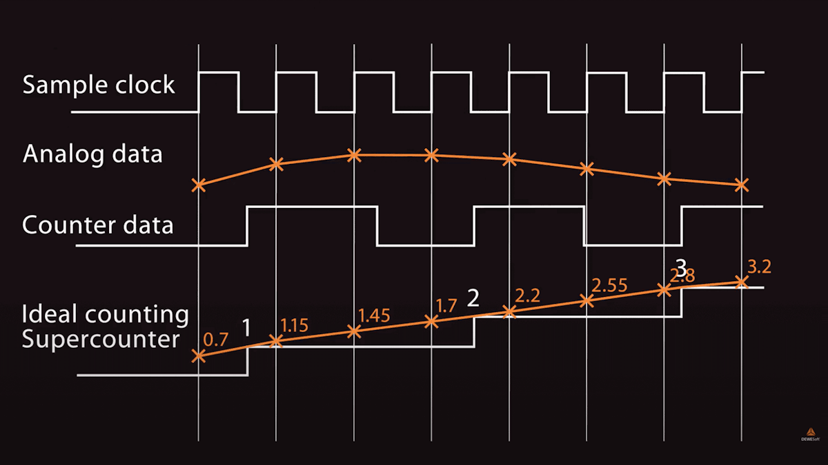
The standard counters available on most DAQ systems today provide only integer resolution outputs (e.g. 1, 1, 2, 2). As a result, their outputs are always one sample behind the analog sensor data. This can be a real problem in applications like rotational or torsional vibration when a phase shift of even one sample can change the results.
SuperCounters solve this problem completely by extracting floating-point values like 1.37, 1.87, and 2.37, and then aligning them precisely in time with the rest of your data. In fact, a SuperCounter is really two counters in one. The input is fed in parallel into both counters, and the sub-counter measures the exact time of the rising edge of the signal. Thus the real value of the counter with respect to the analog values is calculated and perfectly aligned.

 are aligned because of the interpolation between values")
The video below shows how SuperCounter technology measures counter signals fully synchronized with the analog channels. This video includes a real-world comparison between normal counting mode and SuperCounting mode.
Other data sources, like CAN bus, XCP, video, and others are also synchronized with the analog data in all Dewesoft data acquisition systems.
The other “secret” behind this technique is that Dewesoft’s SuperCounters run on a 102.4 MHz time base that is independent of and much higher than the analog sampling rate.


The importance of electrical isolation
Isolation is every bit as important in the digital realm as it is in the analog realm. Noise riding on top of digital lines can be easily mistaken for real events, and thus miscounted. This is why Dewesoft DAQ hardware provides robust isolation on all digital and counter-line inputs.
The importance of filtering
In the real world, noise and glitches on the counter outputs are not uncommon. The problem is that if glitches are high enough in amplitude they can be counted as pulses, resulting in wrong values. Dewesoft SuperCounters provide advanced filtering on their inputs that you can use to mitigate this problem, just as you do in the analog domain.
In the graphic below you can see that the second red pulse is really a glitch, but that it is big enough that it has been counted as a pulse (see the blue step directly below it - the output of the event counter).


Operating modes
You can do a lot with these SuperCounter digital inputs. SuperCounter hardware is tightly integrated with DewesoftX software, providing access to a great selection of capabilities:
Event counting mode (basic, gated, up/down, basic encoder)
Sensor mode (encoder, tacho, CDM, 60-2,...)
Waveform timing mode (period, pulse-width, duty cycle)
Let’s take a look at these modes and how they apply to the sensors in the previous sections of this article.
Event counting mode
In event counting mode DewesoftX software provides several ways of counting the pulses of an incoming pulse stream, including:
Basic Counting
Gated Counting
Up/down Counter
Basic Encoder
Basic counting
In basic event counting mode, we can count either falling or rising edges of the signal. You only need to connect the signal to one of the counter inputs and ground.


In the software, select the Event Counting application, then the Basic Event Counting mode. Now just let the software know which input pin you connected the signal to. You can elect to have the system count UP or DOWN. There’s a checkbox to reset the count at the start of measurement or not.


Gated counting
In gated counting mode we will only count a pulse when a gated signal is high. You connect both the pulse signal itself to input IN0 (and ground) and connect a second signal to input IN1, to serve as the gate signal.


Note that there are INV (invert) checkboxes by both inputs. This is important so that you can set the proper polarity of your signals. For example, if the gate signal is normally high, but you need it to be normally low, you can check the INV box next to the Signal gate selector.


Up/down counting
Up/down counting mode is similar to the gated counting mode above, except that the gate is used to control whether we count up or count down. When the gate is high and a pulse occurs we count UP, and when the gate is low and a pulse occurs we count DOWN.


The setup is the same as with gated counting mode. And as always, the filtering, reset at the start of measurement, and INV controls are included.

Basic encoder counting
In basic encoder counting mode, we can set up just about any incremental encoder on the market today in a very flexible and intuitive way.


Referring to the screenshot, just select the encoder mode at the top left of the DewesoftX counter setup screen. Like before, the Signal A and Signal B inputs in the middle of the screen should be selected (normally they are wired to IN0 and IN1 respectively).
Note that if you want to use the Z (zero position) output from the encoder, you need to check the Encoder Zero box near the top right of the screen. When you do that, a new dropbox menu box will appear below Signal A and Signal B so that you can select the input line used for the zero signal:
Normally this will be the IN2 line, as shown above.
What kind of outputs would you like from the encoder?
In the bottom section, you can select from the angle channel whether you want COUNTS, REVOLUTIONS, or DEGREES. In the screenshot above we have selected REVS.
You can also input a scaling factor if desired. The default x and b values are 1 and 0 as shown above. It’s a basic linear y = mx + b scaling method,
Where:
X = the scaling multiplier (can be a floating-point or integer value; 1 = no multiplier)
B = the offset (can be positive or negative; 0 = no offset)
The Frequency line can also provide Counts or RPM (revolutions per minute), as shown in the selector.
Now let’s look back at the top right corner of the screen. We have to tell the software how many pulses per revolution are outputting. In our example screen, it’s a 360 encoder, so it’s outputting a pulse every 1° around one rotation. You should input the correct resolution for your encoder (it’s usually labelled right on the sensor).
Next, you can set the encoder mode. Here is what X1, X2, and X4 mean:
X1 mode - In this default mode, the rising edges from source A will be counted.
X2 mode - In this mode, the counter will count the rising AND falling edges of source A will be counted, so the resolution will be increased by a factor of 2. Everything else stays the same.
X4 mode - In this mode, the counter will count the rising AND falling edges of source A AND source B will be counted, so the resolution will be increased by a factor of 4. Everything else stays the same.
The purpose of these X2 and X4 modes is to get more resolution from the encoder, but you should take care because unless the duty cycle is not exactly 50%, or in X4 mode if the A and B tracks are not precisely aligned, measurement errors due to mechanical “jitter” can be introduced.
It should be mentioned that there are encoders with a lot more resolution than 360 pulses per revolution, so engineers can match the sensor to the measurement requirements in a flexible way.
Sensor mode
In sensor mode, you configure the counter for specific sensors, including:
Encoders
Tachometers
CDM sensors
60-2 sensors
And more
Of course, you could set all of these up manually using the methods shown in the preceding sections, but DewesoftX software includes a sensor database where you can create, edit and reuse your specific sensors, making setup fast and easy. Why start from scratch when using the same encoder or proximity sensor that you used a few days ago? With a few simple steps, you can add any sensor to your database, and then simply select it by name the next time you use it, and it will be set up in the software as fast as you can blink.
Waveform timing mode
In waveform timing mode DewesoftX software can provide several useful calculated outputs from any incoming pulse stream, including:
Period
Pulsewidth
Duty-Cycle


Discrete digital input mode
Each counter has three inputs - so you can freely use them as discrete digital inputs (instead of as a counter). In this case, you don’t use the counter module but set up one or more digital inputs within the DewesoftX software.
And it’s really as simple as activating one or more of your digital inputs on the software setup screen.


There is virtually no configuration because the inputs are either 0 or 1, and no other values are possible. You could set the channel name, colour, and engineering units (EU), as shown in the following screenshot:
Then on the display screens, simply apply these digital inputs to any of the visual displays that you desire. These channels will be stored along with the other data. It’s that simple.
To go further, you can use these discrete values in math formula channels, or as the input to one or more trigger channels that will start and/or record.
Dewesoft DAQ systems with digital Inputs
SIRIUS DAQ systems
Most SIRIUS data acquisition devices have optional SuperCounter inputs. Each SIRIUS slice consists of 8 analog input channels, it is possible to configure it with up to 8 counters per slice (depends which analog input connectors are used).


SIRIUS standard input modules
| Module | STG | STGM | ACC | CHG | HV | LV |
|---|---|---|---|---|---|---|
| Counter version? | √ | √ | √ | √ | X | √ |
SIRIUS HS (high speed) input modules
| Module | STG | ACC | CHG | HV | LV |
|---|---|---|---|---|---|
| Counter version? | √ | √ | √ | X | √ |
Note: SIRIUS-HD slices cannot have SuperCounter inputs due to limited space on the chassis.
For high-quantity, discrete input applications, The SIRIUS STGM-DB module has an additional DSUB-37 male connector which provides 24 dedicated digital inputs. These 24 inputs can alternatively be used for 8 counter/encoder sensors.
DEWE-43A DAQ system
The DEWE-43A is a handheld 8-channel DAQ system that provides eight SuperCounters as standard. Each counter is independent, and can alternatively be used as three discrete inputs instead of as a counter.


KRYPTON DAQ systems
KRYPTON and KRYPTON ONE are extremely rugged DAQ modules, rated to IP67 for operating in harsh environments with shock, vibration, and high and low-temperature extremes.


KRYPTON and KRYPTON-1 rugged digital modules
| Module | Counter Inputs | Discrete Inputs | Discrete Outputs | Input Data Rate | Output Data Rate |
|---|---|---|---|---|---|
| KRYPTON 4xDI | - | 4 | - | 40 kS/s/ch | N/A |
| KRYPTON-4xDO | - | - | 4 | N/A | See Note |
| KRYPTON-1xCNT | 1 | - | - | 10 MHz | 20 kS/s/ch |
| KRYPTONi-16xDI | - | 16 | - | 20 kS/s/ch | N/A |
| KRYPTONi-8xDI-8xDO | - | 8 | 8 | 20 kS/s/ch | See Note |
| KRYPTONi-16xDO | - | - | 16 | 20 kS/s/ch | See Note |
Note: Output rates depend on the selected EtherCAT master.
IOLITE DAQ systems
Dewesoft IOLITE DAQ systems offer a 32-channel digital input module. This model 32xDI with easy screw terminal hookup and sensor power supply is ideal for high channel count data acquisition and control applications.


IOLITE combines powerful data acquisition with real-time control via dual EtherCAT interfaces. Available in a 19” rack model as well as a benchtop model. There are digital input and output modules available for IOLITE, as shown in the table below.
IOLITE digital I/O modules
| Module | Discrete Inputs | Discrete Outputs | Input Data Rate | Output Data Rate |
|---|---|---|---|---|
| IOLITE-32-DI | 32 | - | 40 kS/s/ch | N/A |
| IOLITE-32-DO | - | 32 | N/A | See Note |
Note: The Digital output rate depends on the EtherCAT master.