


How Are ADAS Systems and Autonomous Vehicles Tested?

October 12, 2021
This article talks about ADAS testing and explains how ADAS systems and autonomous vehicles are tested. We will cover the topic in enough depth that you will:
Understand why it is important to test ADAS systems
Learn how ADAS systems and autonomous vehicles are tested
See what type of equipment we use for ADAS testing
This is PART 3 of 4 in the ADAS series:
Part 1: What is ADAS?
Part 2: Types of ADAS sensors in use today
Part 3. How are ADAS systems and autonomous vehicles tested (this article)
Part 4. ADAS standards and safety protocols
The imperative of ADAS testing
The complex technologies behind ADAS must be tested, and not just in software models, but on the ground, with vehicles and human drivers interacting on real roads under realistic conditions. For that high-end Data acquisition hardware and software need to be installed inside these vehicles.
Automotive test engineers have been instrumenting vehicles for nearly a century. The challenge now is that they have to test interactions among multiple vehicles (and pedestrians) in real-time. When cars are driving we can’t run wires between them. The vehicles and the ground station must be interlinked wirelessly, and it must be a high-speed and robust connection.


Furthermore, the data from multiple test vehicles moving around in three-dimensional space must be precisely time-aligned, so that the data can be analyzed in a meaningful way. Microsecond-level time accuracy is the benchmark. We also need to know the exact distances and attitudes between and among the cars and important objects around them.
For vehicles to be capable of 100% autonomous driving under all conditions someday, they must be able to detect and adapt to a wide variety of conditions:
The expected and unexpected movements of other vehicles
Pedestrians in the lane of travel and crosswalks
Debris and unexpected matter in the lane of travel
Undocumented temporary changes due to construction or roadway modifications
and more
It’s a long list with nearly incalculable variations. Simulation is a big part of testing, but real-world testing is essential, so new testing methods have been developed in the world of ADAS, as described in the following sections.


The development of ADAS systems requires complex testing, including the ability to control and calculate relative positions between multiple vehicles and objects in real-time, across a large test track. Real-world interactions among multiple vehicles must be tested and analyzed under a staggering number of possible conditions.
In fact, it’s not just data acquisition. A wide range of systems is needed to perform ADAS testing. Complex tests involving multiple vehicles and objects require modern test tracks and equipment like:
Driving robots
GPS/GNSS
IMU and INS sensors
High-speed wireless car-to-car, and car-to-base data networking
ADAS targets
Proving ground tracks
Entirely new ADAS testing tools have been developed and are available at today’s proving grounds. There are also partial and completely autonomous testing tools, primarily in the simulated testing world. Simulated testing is essential, but in this article, we will keep the focus on real-world testing.
In part 2 of the ADAS article series, we outlined the range of sensors installed on ADAS-equipped vehicles: cameras, RADAR, LiDAR, SONAR, IMU, and GNSS navigation systems. To test them we need even more accurate versions of the same sensors to be installed onto test vehicles. We will cover all of them in this article.
Driving and steering robots
Driving, aka steering robots, are used for the computerized operation of motor vehicles. They are typically designed so that they can be fitted onto a standard car, truck, or bus without the need to remove the steering wheel or modify the vehicle in any significant way.
They are often affixed to the vehicle’s windshield using high-powered suction cups. They do not interfere with the standard steering wheel airbag. Most of these robots offer brake, accelerator, and clutch pedal controls as optional or standard. They have digital interfaces to a variety of navigation and automation systems on the market.
Driving robots provide a level of repeatability that human drivers are simply not capable of doing. They can execute the same exact manoeuvres time after time. This means that tests are conducted according to standards, and that test results can be more easily compared and analyzed.
Steering robots are essential for, as well as standard NHTSA roll-over tests, such as Fishhook and J-Turn, UN Reg 13-H / FMVSS 126 sine-dwell tests, and more.
There are also braking and pedal robots available, separate from steering robots. Most manufacturers in this field make both. Companies involved in steering robot technologies include AB Dynamics, Humanetics, and Stähle.
Inertial measurements units (IMUs) and inertial navigation systems (INS)
The terms IMU and INS are often used interchangeably, but they are really two parts of the same thing. An IMU is an actual sensor, made up of accelerometers, gyroscopes, and often magnetometers. These outputs are fed into the INS, which uses them to calculate linear velocity, linear position, angular rates, and more.
Inertial Measurement Units are used to measure and output several parameters:
Acceleration
Orientation
Angular rates
Gravitational forces
They are typically made up of three accelerometers and gyroscopes: one each for the axis, defined as roll, pitch, and yaw. They may also contain three magnetometers. High-quality IMUs provide accurate measurements of all vehicle dynamics, including side-slip angle. All data is transferred to a master system which obtains real-time measurement results during the test run.


There are several basic technologies employed by the various IMUs on the market today:
FOG - Fiber Optic Gyroscope
RLG - Ring Laser Gyroscope
MEMS - Micro-Electro-Mechanical Systems
Each of these basic technologies has advantages and disadvantages. RLG and FOG sensors have long provided the highest performance, albeit at a price. MEMS sensors are considerably less expensive but still offer very good performance.
Adding IMUs to a GPS/GNSS system adds dead-reckoning capability since the IMU provides attitude, velocity, and position information even when GPS satellites are out of view, for example, when driving through tunnels or under bridges.
The DS-IMU1 and DS-IMU2 from Dewesoft combine gyroscopes, accelerometers, magnetometers, pressure sensors, and a high-speed GNSS receiver. Coupled with sophisticated algorithms they deliver very accurate and reliable navigation and orientation at up to 500 Hz output data rate. The DS-IMU2, in particular, is compatible with all of these types of tests:
ADAS
Brake/Acceleration
Vehicle dynamics
Lane change
Circle drive
Chassis development
Comfort testing
Pass by Noise
FuSi (functional safety)
Companies that make IMUs for ADAS applications include Dewesoft, OxTS, Genesys, and Xsens.
GPS/GNSS sensors
An absolutely critical component in today’s ADAS testing is highly accurate GNSS/GPS positioning systems. These systems are used to measure relative positions and velocity among vehicles and objects very accurately and with fast update rates.


Single or multiple vehicles can be monitored in three-dimensional space. Synchronized data from all vehicles provides very accurate position and distance information relative to each other and/or to a fixed object.
Improving accuracy with real-time kinematics (RTK)
Real-Time Kinematic is a technique used to increase the accuracy of GNSS positions using a fixed base station, that wirelessly sends out correctional data to a moving receiver.
Many GNSS and IMU navigational devices can be upgraded with RTK (Real Time Kinematic) technology. RTK improves positioning accuracy down to 2 cm (0.79 in.) with the combination of a GNSS receiver and additional base station.

 measurement system illustration")
By utilizing corrections from a fixed base station, the GPS device can fix the position of the antenna to within 1-2 cm. The technique involves the measurement of the carrier phase of the satellite signal, which is then subjected to sophisticated statistical calculations in order to align the phase of these signals. These corrections eliminate the majority of normal GPS-type errors.
This alignment process goes through three phases:
acquisition,
ambiguity ‘Float’ mode, and
ambiguity ‘Fixed’ mode.
Accuracies in Float mode are in the region of 0.75-0.2 m and 0.01-0.02 m in Fixed mode. The correction signal is normally sent out at intervals of 1 second but can be increased if needed in order to reduce the required data rate.
Wireless data transfer using robust WIFI technology
Robust WLAN solutions are used to maintain communication between vehicles and between vehicles and ground stations. There is theoretically no limit to the number of vehicles within this measurement - usage is only constrained by the aggregate WLAN bandwidth.


Systems like the DS-WIFI from Dewesoft are Wi-Fi modems for long-range wireless data transfer between digital data acquisition systems. It is perfectly suited for testing moving objects and for remote measurement applications.
Compared to wired connections, WiFi Data Acquisition offers freedom and flexibility. Wireless connections are absolutely required when conducting ADAS tests. WiFi antennas are mounted onto vehicles using very strong suction cups.
This allows test data to be transferred to the ground station in real time. It also allows ground station personnel to observe the test in real-time and even control the test setup remotely.
Wireless transfers can reach up to 2 km (1.24 miles) range in line-of-sight. Selectable Dual-Band frequencies of 2.4GHz and 5 GHz are supported. Because testing takes place outdoors in a wide variety of environments, the antenna and housings are built into rugged, waterproof sealed industrial-grade metal cases.
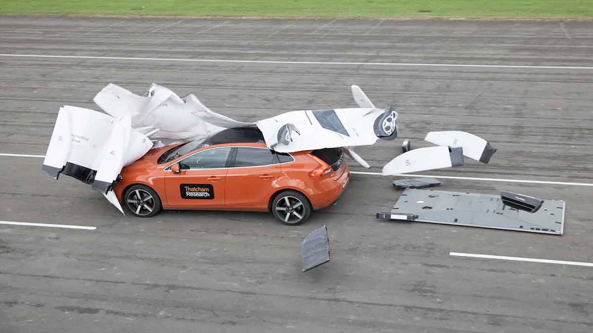
ADAS soft targets
ADAS vehicle targets aka “soft targets” are designed to resemble vehicles and other objects on the road, including cyclists and pedestrians. They are realistic enough to convince the camera and other sensors in the test vehicles that they are real. But colliding with them does not destroy them, or damage expensive test vehicles.
Guided soft targets
These targets are remotely controlled vehicles made of soft materials that break apart easily in the event of a collision. They look like a car or trucks but are empty inside. After a collision, they can be rebuilt in a matter of minutes and be ready for the next test.


Some models, like those made by Humanetics, are composed of several inflatable parts. These 3D “dummy” vehicles typically include a fabric “skin” that makes them look very realistic to the vision systems of the car under test. Some soft targets include remotely controllable headlights, brake lights, and turn signals, supporting a broad range of ADAS tests in a safe environment.
Mounted on a very low propulsion platform that can be driven over without damaging it, guided soft targets can be driven up to 80 kph (~50 MPH), and include braking controls. Some manufacturers specify that they can be controlled within 10 cm. ADAS soft targets are very important for Euro NCAP tests as well as a wide variety of ADAS tests in general.
Pedestrian and cyclist soft targets
Available both in adult and child sizes, these targets are remotely controlled human-shaped dummies. Some of these human targets are also articulated, which means that their legs move like human beings as they move along the road on the test track.


These targets can be mounted on a very low propulsion platform, or they can be mounted on an arm connected to the propulsion platform so that test cars that hit them won’t be damaged by running over the propulsion platform. Dummies can be configured as pedestrians, cyclists, scooter riders, and more. Some models are propelled on a remotely controlled platform, while others are towed using flat cables connected to motors located on the side of the track.
Video showing various pedestrian dummies being used for EURO-NCAP autonomous emergency braking AEB tests.
Companies involved in ADAS target technologies include AB Dynamics, Humanetics, and 4activePA.
Video cameras
Cameras are indispensable sensors in a wide variety of automotive testing applications, including ADAS testing. The video data from these cameras, in sync with the data, provides important context, meaning, and value.
The most critical aspect of adding cameras to the test is that the resulting video data is synchronized with the GPS, CAN, and analog data. The DS-CAM camera series from Dewesoft have a sync interface that, combined with DewesoftX software, time-stamps each video frame in the data file. The video data are stored alongside the rest of the data and are displayed and replayed seamlessly together.


DS-CAM cameras offer high-speed video with up to 333 FPS at full HD resolution. Lowering the resolution you can achieve up to 600 frames per second (FPS). These cameras have real-time onboard JPEG compression, allowing them to stream directly to the computer's hard drive. Several models are available:
| Camera model | Sensor type | Resolution | FPS |
|---|---|---|---|
| DS-CAM-88 | CCD | VGA 640x480 | 88 FPS @ 640x480 167 FPS @ 320x240 289 FPS @ 160x120 |
| DS-CAM-120 | CCD | VGA 640x480 | 120 FPS @ 640x480 |
| DS-CAM-175 | CMOS | 1456x1088 | 68 FPS @ 1456x1088 116 FPS @ 1280x720 145 FPS @ 800x600 178 FPS @ 640x480 |
| DS-CAM-320 | CMOS | 728x544 | 266 FPS @ 728x544 328 FPS @ 640x480 |
| DS-CAM-600 | CMOS | Up to Full HD 1920x1080 | 334 FPS @ 2048x1080 600 FPS @ 800x600 |
These cameras are rugged and provided with threaded holes for standardized mounting. The DS-CAM-600 model is available in an IP67 version, which means that it’s fully waterproof and dustproof, and can be used on the outside of the vehicle. Up to eight cameras can be connected to a single DAQ instrument and synchronized to the data - even if they are running at different rates. Up to eight cameras running at 333 FPS at Full HD resolution are possible.
LiDAR sensors
LiDAR (Light Detection and Ranging) systems are used to detect objects and map their distances in real time. As a LiDAR sensor rotates, it emits laser beams in all directions. The time it takes the beams to bounce back is measured and used to construct a high-resolution three-dimensional model of its surroundings.
LiDAR sensors are being incorporated into ADAS and autonomous vehicles because they are critical sensors. But the LiDAR sensors discussed in this section are the more expensive and capable ones that are used for ADAS testing. They are typically mounted on the hood or roof of ADAS test vehicles and used in proving ground tests.


California-based company Velodyne manufactures state-of-the-art LiDAR sensors for ADAS testing and other applications. Data acquisition system manufacturer Dewesoft provides an interface for capturing and synchronizing the Velodyne output with the rest of the data. Using DewesoftX DAQ software, engineers have a complete view of data from analog sensors, the CAN bus, video cameras, GPS, LiDAR, and more.
LiDAR systems can be synchronized with GNSS (Global Navigation Satellite System) and GPS (Global Positioning System) devices using the PPS (pulse per second) signal. In this configuration, the GNSS receiver is the source of NMEA (National Marine Electronics Association) GNSS messages for the LiDAR sensor. The LiDAR and GPS/GNSS are connected directly.
NMEA messages are also available as standard navigational channels in the DAQ software.
Proving grounds for ADAS testing
A proving ground is an area where the performance of a vehicle is put to the test. Proving grounds are generally spread over large areas and roads (usually several kilometres or miles) and have garages and related facilities to assess the working of various systems and parts of the vehicle. Proving grounds, also known as “test tracks,” have provided on-road and off-road vehicle testing for decades.


Until the 1920s, automotive testing was done on city streets and country roads. Proving grounds move vehicle testing from public roads to controlled, secure, and safe testing environments while simulating a wide range of road types and events, all reflecting or relating to the customer's usage of the vehicle.
For cold-weather testing, the best-known facility is in Arjeplog, Sweden, just 50 km (~35 miles) from the Arctic circle. Regular roads and bridges are used in combination with the frozen lake, which has roads marked on it in the Winter for a broad range of tests. Most proving grounds around the world are private facilities to ensure safety, as well as keep new designs away from the competition.


For a comprehensive list of automotive proving grounds, please see the interactive list of automotive proving grounds.
ADAS software
ADAS software is needed to record data from all vehicles and other objects included in the ADAS test. ADAS software needs to have the capability of acquiring data synchronously from multiple vehicles at the same time and different types of ADAS sensors. It also needs capabilities of performing measurement and various calculations such as:
Measure the object's speed, acceleration, deceleration, heading
Measure and calculate distances between moving and static objects in real-time
Measure and calculate angles between objects
DewesoftX software which is included with their data acquisition systems and inertial measurement units offers an add-on called Polygon, developed specifically for ADAS testing needs.
Polygon is a virtual 3D platform for tests involving moving and static objects. It was made especially for ADAS and vehicle dynamic testing, which increases safety in traffic. The Polygon add-on provides a visual representation of measurements in the three-dimensional virtual space and easy tools for geometric measurements between multiple static or movable objects. Due to its flexibility, it's not only used for testing automotive autonomous vehicles but also in marine and heavy machinery sectors.
Polygon add-on allows you to define several object types and performed different calculations between them. The following object types can be defined inside a polygon:
Vehicles
Simple objects (cone)
Line
Multipoint line - route
Circle
Travel radius
Import
These objects can be defined as:
Static objects
Moving objects
Moving with other objects
Freeze/Unfreeze on the trigger
Once objects are defined, the Polygon will be able to make several calculations between defined objects in real-time and appropriately visualize them on the display. These calculations include:
Distance: Calculates the distance between two objects. Both objects can be moving or one can be fixed. All types of objects are supported for distance calculation.
X and Y distance: Calculates longitudinal and lateral distances, looking from the first object. Distances can be calculated between vehicles and simple objects (fixed or moving). If the X and Y position of an object on the fixed coordinate system is required, you can put a simple object in the centre (at position x=0, y=0). The polygon then calculates the X and Y distances from that object to the moving object.
Angle: Calculates the heading deviation between two objects. It can be calculated between two vehicles or Line, Route, Circle or Travel radius, and Vehicle (vehicle should always be the second object).
Gate cross trigger: Changes its value from zero to one and back to zero again when a moving object crosses a defined line. The first object must always be a line (representing the “gate”), and the second object must be a vehicle or a simple object (i.e., a custom interest point).
Time: Outputs relative time from the previous time reset in seconds and resets the timer. One of the objects in the measurement has to be a line. Output is changed when the other specified object (vehicle, simple object) crosses the line centre. One line with a time setting can be used to record lap times on a looped track.
Time reset: Resets the relative timer and outputs the absolute time from the start of measurement in seconds. One of the objects in the measurement has to be a line. Output is changed when the other specified object (vehicle, simple object) crosses the line centre. Normally this setting is used on start lines of non-looped tracks (acceleration runs, brake tests).
Radius: Outputs the specified travel radius value in meters. It uses only the specified travel radius for the object of measurement. It can be set to output either radius or inverse radius. An inverse radius is used when we want to avoid the large values of the radius when the moving object path comes close to a straight line.
ADAS software such as DewesoftX together with the Polygon add-on offers a great virtual platform for testing all sorts of ADAS scenarios on proving grounds or real-road conditions. Several vehicles can be equipped with Dewesoft data acquisition instrumentation and displayed in real-time using DewesoftX software.
What about consumer-level ADAS calibration?
In the previous sections, we have discussed how engineers test ADAS systems during their development, using real drive testing as well as software simulation. All of this happens before the cars’ designs are finalized, manufactured, and then delivered to consumers.
But what about after a new ADAS-equipped vehicle is parked in front of your house? Do the ADAS systems require checking and calibration from time to time? Just like any other part of the car, the answer is yes.
As you have learned in part 1 of this article, ADAS systems are heavily dependent on sensors, which must be operating at peak efficiency and efficacy in order to allow the ADAS system to work as designed. There is also a powerful processor behind the scenes. It handles gigabytes of sensor data and uses it to perform driver assistance warnings (passive safety measures) and to take action to keep the vehicle in its lane, automatically brake and steer to avoid collision (active safety measures), and more.
In fact, automobile manufacturers are increasingly recommending and even requiring consumers to have their cars’ ADAS system recalibrated under these circumstances.
ADAS warning lights flashing or indicating a fault
This one is obvious: if your car is telling you that something is wrong with the ADAS system, it should be checked and brought back to factory OEM standards immediately.
Windshield repair or replacement
Several ADAS sensors are mounted either near or behind the windshield, so when a windshield is replaced or compromised in any way, it can affect these sensors. This is why several companies that perform windshield replacement and repair have expanded into the recalibration of ADAS sensors. USA-based Safelite Autoglass offers ADAS camera recalibration as a part of their windshield repair services. They offer both static recalibrations where the car is parked and facing a calibrated target, and active recalibration, where the car is driven on a well-marked road.


Safelite is present across the entire USA. There is probably a company in your town that performs advanced driver assistance systems calibration. An increasing number of car dealers can perform ADAS calibration to ensure that the systems conform to the manufacturer’s OEM specifications. Now, other companies are entering the market as well.
Accidents
A collision causes very obvious damage to the body of the car. But the impact can also affect systems that you cannot see, including the ADAS sensors and system. Checking and, if necessary recalibrating, the ADAS system should be part of any post-collision repair.
Changes in the car’s height
ADAS systems like parking sensors and others are calibrated for a specific ride height. But if different diameter tires are installed, or significant modifications to a car’s suspension have been made, the ride height can be changed. It is important that the sensors be calibrated to the actual ride height of the car so that they can work as designed.
Consumers should always verify that the repair facility is trained in performing ADAS system calibration according to the car maker’s factory specifications.
What about cyber security?
The more connected something is, the greater the risk of hacking. We have seen bad actors hijack the computer systems of banks, towns and cities, and oil pipeline operators, and hold them hostage until a ransom is paid. In a future when most or all vehicles on the roads are interconnected, how can we be sure that a single car or truck … or a fleet of them … is not attacked?
An independent study commissioned by SAE and Synopsis reveals that 30% of automobile makers and suppliers do not have an established product cybersecurity program or team. And 84% of the respondents to the survey are concerned that cybersecurity practices are not keeping pace with the ever-evolving security landscape.


Today’s cars, trucks, and even motorcycles are basically “self-contained rolling IT networks” that incorporate control systems, entertainment systems, and wireless communication across numerous protocols. The driver’s and passengers’ cell phones, tablets, and other devices can and often do also connect to the vehicle for entertainment, communication, and navigation. They also expose the vehicle to the internet at large, and increasingly, vehicles have their own wireless link to the internet. The potential for hacking has never been greater.
One of the conclusions of this report is that the technologies that pose the greatest risk are RF technologies, telematics, and self-driving vehicles.
To combat this risk, the SAE developed J3061, the world’s first automotive cybersecurity standard. At its core, JAE J3061 emphasizes that cybersecurity should be integrated into vehicle design from the very start, not added later. The pressure to get new vehicles from design to the showroom as quickly and economically as possible has a powerful effect on OEMs and suppliers alike. As vehicles get more interconnected, rigorous testing against vulnerabilities at all stages of product design and development must keep pace. Development testing at this stage is crucial.
A revision to the ISO 26262 Automotive Functional Safety standard is underway, and a working group made up of both ISO 21434 and SAE J3061 has begun the development of an overall cybersecurity standard for tomorrow’s vehicles. A UN Task Force on cybersecurity is also addressing this increasingly important topic.
Summary
Every machine has to be tested to make sure that it is working according to its design and safety protocols. Cars, trucks, and buses are among the most complex machines that the average person will ever operate.
ADAS technology and its safety features have been developed to improve the safety of our roadways by preventing the human errors that are responsible for the vast majority of accidents. Therefore, nothing is more important than ensuring that ADAS technology itself is safe and reliable. Testing has never been more important.
This is PART 3 of 4 in the ADAS series:
Part 1: What is ADAS?
Part 2: Types of ADAS sensors in use today
Part 3. How are ADAS systems and autonomous vehicles tested (this article)
Part 4. ADAS standards and safety protocols