


Development and Testing of a Hybrid Rocket Engine
Alberto Boffi, Agar Firenzuola, Nicolo Florio, Federico Giambelli, Paolo Gnata, Alberto Nidasio, and Elena Ventola
Skyward Experimental Rocketry, Politecnico di Milano, Chimæra Team
March 30, 2026
The goal of the Propulsion Department of Skyward Experimental Rocketry for the season 2021/2022 was to design, build and test a hybrid rocket engine, named Chimæra. The Department aimed to find major development points in order to compete with an evolved version at EuRoC 2023. An extensive and meticulous fire test campaign was needed and in these crucial activities, hardware and professionals from Dewesoft played an important role.
EuRoC and Skyward
EuRoC is a European annual competition for experimental rocketry, organized by the Portuguese Space Agency, in collaboration with several private industries from the aerospace market. Only student associations from the best European technical Universities can participate. The 25 competing teams are challenged in engineering accuracy rather than brute force. The main goal is to bring a rocket, designed, assembled, and tested by students, as close as possible to a set highest point, a target apogee.
The flight categories are distinguished by:
Target apogee: 3000 or 9000 meters.
Propulsion type: Teams can compete with either COTS (Commercially Off-The-Shelf) or SRAD (Student Researched and Developed) engines. These are divided into propulsion system types: solid, liquid, or hybrid.
Skyward is a student association born in 2012 at Politecnico di Milano, Italy, with the ambition to allow students to deepen topics treated in class, by competing at the international level. Skyward has around 170 members and external advisors, of which a few less than 100 are actively working on ongoing projects.
Skyward has been competing yearly at EuRoC since 2020: Lynx and Pyxis are the two rockets launched in Portugal at the 2021 and 2022 competition editions – see figures 1 and 2.


Both the rockets are entirely built by Skyward members, except for the COTS solid motor, to compete in the 3000 meters apogee flight category. Both rockets had great success in Portugal. Lynx won 1st place in its flight category, with an apogee of 3076 meters, and obtained the award for the best team organization and team spirit, reaching 2nd place in the overall ranking. Pyxis, one year later, won the competition, getting overall 1st place for the technical report, the best antennae, and the full score in almost all rankings.
Nonetheless Skyward has no intention to settle for these achievements: the new goal is to create a rocket entirely made by students. To achieve this goal, the Propulsion Department has been designing, building, and testing a hybrid rocket motor called Chimæra - a name taken from a fire-breathing female monster in Greek mythology. The engine was completed in September 2022 and will be further developed during the season to compete at EuRoC 2023.
The hybrid rocket engine
To understand how Dewesoft helped Skyward carry on a complete fire-testing campaign, it is necessary first to have an idea of how a hybrid rocket engine works and how Chimæra was tested.
A hybrid rocket engine works for the momentum conservation principle. A mass is accelerated out of the engine, and by reaction, the engine is subjected to a force equal in intensity and direction but with verse opposite to those of the expelled mass velocity.
The mass is produced through the combustion process inside the combustion chamber, where solid state fuel - in this case ABS (acrylonitrile butadiene styrene) - and oxidizer mix and react. This process increases the energetic content of the exhaust gasses, raising temperature and pressure. Such energy, called enthalpy, is converted into kinetic energy through the nozzle (convergent-divergent), and the gas is accelerated up to supersonic velocities.
A rocket engine is called a hybrid whenever the oxidizer and the fuel are stored in different matter states. In the classical configuration, the fuel is a solid grain, situated inside the combustion chamber, while the oxidizer, liquid or gas, is stored in a pressure vessel. The fuel grain has a central cavity, called a port, through which the oxidizer flows and reacts with the fuel, generating the flame.


Chimæra mounts a 3D-printed ABS solid grain with a cylindrical port and uses biphasic (liquid/gas) nitrous oxide as an oxidizer. The engine develops around 1600N of thrust, at a chamber pressure of 20 bar, for approximately 5 seconds of firing.
Testing the hybrid rocket engine
The test campaign of a hybrid engine is focused on the following main goals:
Validation of the oxidizer tank discharge model
Validation of the fuel grain regression model
Check the correct functioning of the chamber from a thermal viewpoint
Grain regression
Regression is the phenomenon that consumes the grain during combustion. The internal surface of the port is gradually pyrolyzed, generating a gaseous fuel flow, that reacts with the injected oxidizer. Thus, port geometry varies and so do the performances. The model used to simulate this behavior is semi-empiric: thus, it needs a tuning phase, supported by experimental data specifically retrieved on each engine configuration.
Tank discharge
Nitrous oxide is not simpler to model, as its biphasic state reaches temperatures below 37°C. During the combustion process, part of the nitrous oxide is injected inside the chamber through the injector. Then, the tank progressively empties, losing pressure and causing the boiling of the free surface; this phenomenon produces a boiled gas mass flow rate lower than that of the discharged liquid. Also, in this case, lots of accurate experimental data are necessary for evaluating model reliability.
Chamber thermal behavior
Together with data gathering finalized to estimate engine performances, it is important to verify its structural integrity. One of the most critical subsystems is, for sure, the nozzle, where the highest thermal fluxes are localized. Then, an adequate quantity of data on the temperatures in that zone should be granted to validate the thermal models implemented by the team. The goal is to avoid and foresee thermal or thermo-mechanical failures, which would prevent the correct functioning of the engine.
To conclude, the measurements needed for a complete fire test campaign are:
Combustion chamber pressure
Oxidizer pressure before the injector
Oxidizer tank pressure
Engine thrust
Nozzle temperatures
Test setup and hardware used
Test setup outline
A static fire test is composed of two main phases:
Refueling, during which the custom tank is filled up with the oxidizer, using one or more commercial bottles. Note that the commercial bottle shall be rotated upside down so that the liquid phase can flow toward the custom tank. During this process, the internal pressure of the custom tank and the refueled mass are monitored in real-time.
Firing: when the engine is fired and all the important measurements are taken.
The test setup chosen by the team, following EuRoC rules, is the vertical one. In this setup, the combustion chamber and tank are fixed on a test fuselage, which is free to slide vertically on two sliding guides. Next to the 3-meter-high main test stand is a second vertical structure. The latter hosts the commercial bottle used for the refueling process.
All the electronics are positioned on an opposite panel, unconstrained from the test stand, to avoid damage through structural vibrations.


Description of implemented hardware
Two different systems for data acquisition were used:
SRAD system. A DAQ system with remote control capability, developed by the Skyward electronics team, powered at 12 V, featuring:
2x pressure transducer channels with current output up to 1 kHz.
2x pressure transducer channels with voltage output up to 1 kHz.
1x full bridge load cell channel up to 80 Hz.
4x type-K thermocouple channels.
Other interesting features are:
Wireless live telemetry up to 2 Hz.
Local full-frequency data storage on micro-SD.
2x control output for remote-controlled servo valves. More specifically, power availability for two 7.4V servo motors.
The main aim of this system is to allow remote control during the most critical test phases, to grant maximum personnel safety. Its data-gathering performances are, on the other hand, significantly inferior to that of Dewesoft SIRIUS. The retrieved data is mainly used to implement autonomous safety algorithms, conceived, for example, to terminate a test in case of severe anomalies.
This system is complemented by a wireless control box positioned at the ground station and capable of receiving the telemetry and actuating the servo-valves. The ignition is actuated by an ignition box, electrically connected through a couple of power cables to the igniter, situated inside the combustion chamber.
Nonetheless, the control electronics keep the circuit open until the operator responsible for the ignition activates the software. The system can also inject nitrogen inside the chamber to extinguish the flame via a solenoid valve. For redundancy purposes, the valve can be opened either by the electronic system or by a wired electric system reaching the ground station.


Dewesoft SIRIUSe8x STG+ - a data acquisition system powered at 220 V, featuring:
8x STG channels up to 200 kHz with the USB output or 20 kHz using EtherCAT output.
8x CNT channels with a maximum bandwidth of 10 MHz.
Its task is to gather the data necessary to evaluate the performances of the Chimæra. As mentioned, the measurement of all the main parameters used during the post-process activities is left to this system. The system's reliability, acquisition frequency, and measurement quality are significantly higher than the SRAD system.


The sensor configuration implemented on the described systems is reported in Table 1 and visualized in Figure 9 with a P&ID (Piping and Instrumentation Diagram).


STACK
| Code | Sensor | Frequency | Range | Measure |
|---|---|---|---|---|
| TC1 | RS Pro type-K thermocouple | 10 Hz | -20÷250°C | Refueling line check valve temperature |
| TC2 | RS Pro type-K thermocouple | 10 Hz | -20÷250°C | Tank bottom cap temperature |
| PT1 | Trafag 8252 (currentpressure transducer) | 1000 Hz | 0÷100bar | Commercial 40 L N2Otank pressure |
| PT2 | Trafag 8252 (currentpressure transducer) | 1000 Hz | 0÷100bar | Injection pressure |
| PT3 | Omega PX303 (voltage pressure transducer) | 1000 Hz | 0÷69bar | Pre-combustion chamberpressure |
| LC1 | S2 Tech 546 QD 110 kg load cell | 80 Hz | 0÷110kg | Commercial 40 L N2O tank mass |
DEWESOFT
| Code | Sensor | Frequency | Range | Measure |
|---|---|---|---|---|
| TC3 | RS Pro type-K thermocouple | 5 kHz | -20÷1370°C | Retainer ring temperature |
| TC4 | RS Pro type-K thermocouple | 5 kHz | -20÷1370°C | Nozzle temperature |
| PT4 | Keller 33Xe (currentpressure transducer) | 5 kHz | 0÷100bar | Custom tank liquid pres-sure |
| PT5 | Keller 33Xe (currentpressure transducer) | 5 kHz | 0÷100bar | Post-combustion cham-ber pressure |
| LC2 | CAMI 2000 kg loadcell | 5 kHz | 0÷2000kg | Thrust and refuelingmass |
The team has consciously chosen to leave all the critical measures to the Dewesoft DAQ, aiming to minimize the risk of critical measurement failures and maximize the signal’s frequency content.
Results and post-processing
As mentioned, the data analysis procedure focuses on grain regression. The goal is to retrieve the coefficients for the implemented semi-empiric model: the Marxman model. G.A. Marxman and his associates developed the diffusion-limited theory at the United Technology Center (UTC) in California in the 1960s. Their model describes the heat transfer pathways within a hybrid motor.
The Marxman model concerns the velocity of regression of the hybrid engine fuel grain, called regression rate. It assumes that this exclusively depends on the oxidizer mass flow rate per unit area (mass flux), going through the port, The calculation is as follows:
where:
is the grain regression rate, measured in
is the pre-multiplying Marxman ballistic coefficient
is oxidizer mass flux, measured in s
is Marxman ballistic exponent
The most correct way to retrieve and would be to measure the mass flux and the regression rate directly. Unfortunately, this would require using an optical method and a flowmeter, both quite expensive. Thus, the team went for the following solution:
Indirect measurement of the oxidizer mass flux through the injector pressure, using the NHNE model.
Indirect measurement of the regression rate, obtained by solving the combustion chamber mass balance through a pressure measurement.
Tank discharge model
As mentioned, the oxidizer, nitrous oxide or , is in a biphasic state inside the custom tank. It means that at ambient temperature, its vapor pressure is much higher than the ambient one. Then, stored in a closed environment, the boils, and its vapor phase pressurizes the tank at the vapor pressure (around 60 bar at 25 C°C).
The huge benefit is that the oxidizer itself is in charge of pressurizing the tank - such a system is called auto-pressurized. By exploiting this property, there is no need for a complex turbo-pumps system or an external pressurizing tank. On the other hand, a minimum static pressure loss at the engine ignition due to the oxidizer motion in the feeding line determines the transition from saturated liquid to a biphasic state. In this way, the fluid can no more be considered incompressible.
To evaluate the oxidizer mass flow rate by modeling such behavior is complex but feasible. The team used the NHNE (Non-Homogeneous Non-Equilibrium) model to estimate the discharge of nitrous oxide across the injection plate. The fundamental hypothesis is that the mass flow rate that goes through the injector is a weighted average between the theoretical compressible fluid (HEM: Homogeneous Equilibrium Model) and the incompressible fluid (SPI: Single Phase Incompressible). Then, a coefficient takes into account bubbles formation before the injector is applied.
The derived mathematical model is the following:
Where:
l is the oxidizer mass flux in the incompressible case measured in
is the oxidizer mass flux in the homogenous incompressible measured in
is the saturation pressure of the nitrous oxide measured in
is the acquired static pressure measured in bar.
is the nitrous-specific enthalpy measured in .
is the characteristic coefficient of the model
is the nitrous oxide density measured in
is the injector discharge coefficient
is the injection area measured in
indexes the condition before the injector
indexes the condition after the injector
Given that nitrous is found in the saturated liquid phase, a one-to-one dependence between pressure, enthalpy and density exist. Once the pressure is measured, and are retrieved from the Standard Reference Data (SRD) database of NIST (National Institute of Standards and Technology). Finally, in the months before the static fire test campaign, the injector discharge coefficient was evaluated with a series of cold flow tests.
To refine the model, the cooling of the tank due to the oxidizer expansion is taken into account, modeling the vessel as adiabatic.
Combustion chamber mass balance
Considering a control volume inside the combustion chamber, the mass conservation principle states that the mass variation in this volume equals the difference between the inlet mass flow rate and the outlet one. The incoming mass flow rate corresponds to the sum of the injected oxidizer and the consumed fuel per unit of time.
Thus, the mathematical model is the following:
where:
the combustion gas density, measured in .
is the combustion chamber volume, measured in .
is the inlet mass flow rate, measured in .
is the outlet mass flow rate, measured in .
is the oxidizer mass flow rate, measured in .
is the fuel mass flow rate, measured in .
The following relation is obtained when writing the fuel mass flow rate as a function of the regression rate. Substituting the outlet mass flow rate with those that the nozzle can discharge at a given chamber pressure and expanding the terms of volume and density of the exhaust gasses,
where:
is the acquired chamber pressure, in .
is the specific exhaust gas constant in .
is the combustion chamber temperature in .
is the grain length in \(m\).
is the fuel density in .
is the nozzle throat area in .
is combustion efficiency.
is the characteristic velocity in .
and depend only on the chemical kinetics of the reactions happening inside the chamber and are retrieved with the software NASA CEA (Chemical Equilibrium Application). In this case, for the specific combination: ABS (Acrylonitrile Butadiene Styrene), a common thermoplastic used to make light, rigid, molded products, and N2O, nitrous oxide.
There are, therefore, two variables for the given differential equation: the combustion efficiency η and the regression rate r. A second equation is needed for the problem to be well-posed. The team chose the integral mass balance inside the combustion chamber. It states that the integral of the fuel mass flow rate, retrieved from the model during the combustion time, equals the effectively consumed grain mass, directly measured using a precision scale:
where:
is the combustion time, measured in s.
is the difference in grain mass before and after the combustion process measured in kg.
At this point, the problem is set. An optimization code elaborated by the propulsion team solves the implicit differential equation of local balance. It also finds the combustion efficiency that minimizes the residual on the integral balance. Last, a fitting on the regression rate is carried on to find Marxman’s \(a\) and coefficients with a logarithmic regression.
Data processing
Given the excellent acquisition quality of the SIRIUS system, despite the high sampling frequency chosen on the analog channels, the data processing compatible with the post-processing operations was reduced to its minimum.
In detail, the workflow is:
Time standardization: signals deriving from the two different DAQ systems are synced via software on a unique time vector.
Fitting: given the need for integrating and deriving the measured quantities, filtering the input data was not the best option. Instead, a spline fitting is applied. This way, the noise on the signal is not amplified in derivation and integration operations carried on during the post-processing.
Cutting: eventually, only the relevant part of the data is saved. As mentioned in the previous sections, the choice of the sampling window heavily influences the residuals on the integral mass balance - and thus the result of the post-processing.


Test campaign results
The team concluded 6 static fire tests: in the first two the engine did not ignite, due to an antenna and an ignition failure respectively. Unfortunately, the problems did not finish even when the engine ignited. During tests 3 and 4, the nozzle suffered a thermo-structural failure - encountering a shear rupture in the convergent most solicited section. Luckily, the temperature data acquired with SIRIUS allowed the identification of the cause through thorough comparison with the finite element simulations carried on with Abaqus.
The case of failure was attributed to heavy stress concentrated near the sharp edge, as seen in Figures 11 and 12.


The team has proactively solved the problem, re-designing and machining the nozzle and its retainer ring, mitigating the stress concentration, as shown in Figure 13 and 14.


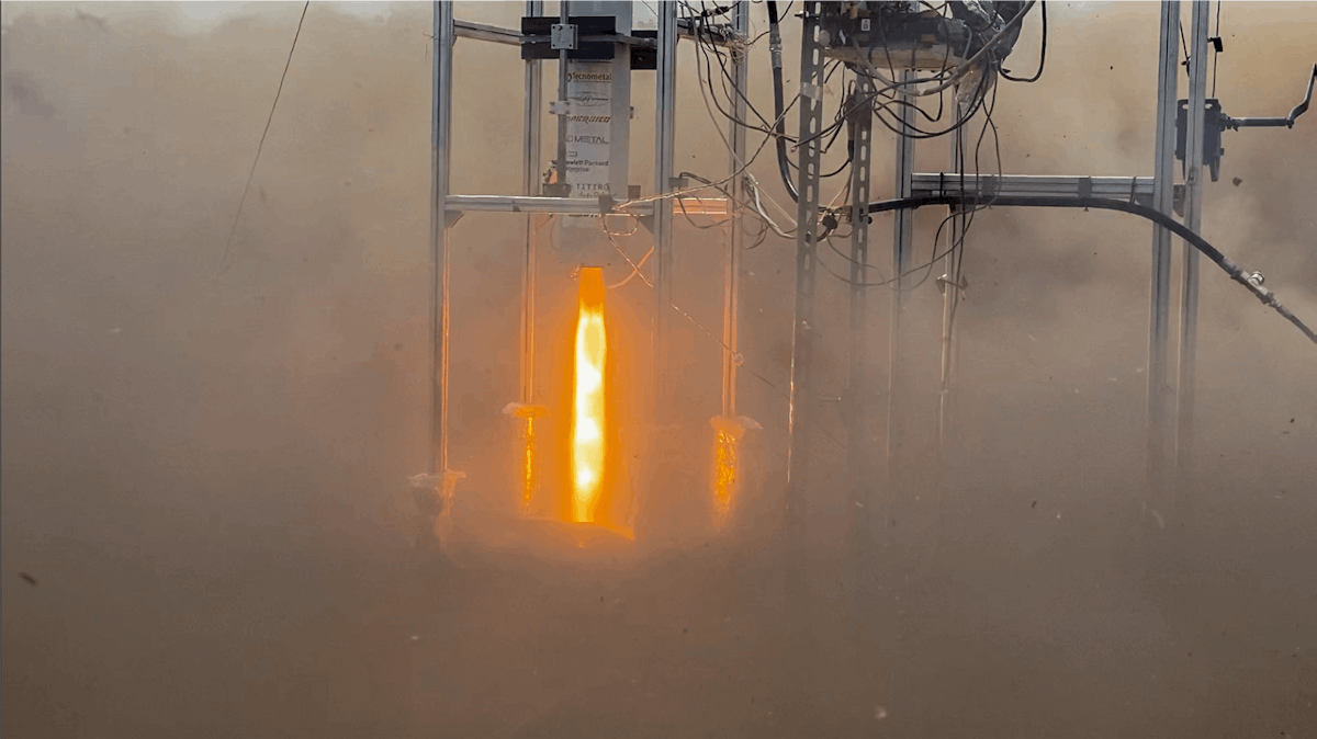
The last two tests were a success. A video shows combustion chamber pressure, tank pressure, and nozzle temperature acquired by SIRIUS, synced in DewesoftX with a recording of the firing.
Given the complexity of the post-processing, the team preferred to exploit the possibility implemented in DewesoftX to export the data in the MATLAB extension. The results of the post-processing made in MATLAB are reported in Figures 15-18.


Results confirm the quality of the acquired data and the correctness of the post-processing activities performed: the compatibility with literature data is excellent. The discrepancy that seems to exist with the Marxman model depends on the fitting method chosen for the purpose. The least squares fitting produces a curve that is in almost perfect accordance with the literature. Nonetheless, the team chooses a simpler logarithmic regression to better model some interesting trends for the particular application.
Comparison with the custom DAQ
The main advantages of Dewesoft SIRIUS are
Reduced sensitivity to external disturbances and high measurement accuracy.
A high acquisition frequency that, in anticipation of 2023, allowed the team to study structural coupling with the rocket.
The extremely intuitive and powerful DewesoftX software allowed the team to monitor, filter, and analyze data in real time.
The system’s stability and robustness even at high environmental temperatures.
The reasons for which SIRIUS was used together with the SRAD system, despite the clear difference in terms of performance, are:
The need for remote controlling the servo-valves implemented for ignition and venting.
The possibility of experimenting with autonomous refueling to minimize risks for the personnel.
This last point creates the need for a unique system capable of sampling some safety parameters and control actuators. Nonetheless, the cost in terms of development and time of a such made system is non-negligible. Thus, SIRIUS allowed the team to concentrate on the evolution of the SRAD system for emergency management, granting the possibility of gathering all critical data simply and reliably.
Conclusions and future developments
The team completed four static fire tests, collecting the data needed for a complete post-process. The Dewesoft acquisition system eased the team’s work on different levels:
Safety
The overall safety during refueling and firing was enhanced. The versatility of the proprietary software DewesoftX allowed for setting overpressure alarms for the combustion chamber and the tank to trigger safety procedures in case of danger.
Time
Using Dewesoft DAQ reduced sensibly the work hours needed to conclude a test. In particular, the ease of setting up both the hardware and the software cut the preparation time of the measurement instrumentation by half. Moreover, the possibility for the operators responsible for the refueling phase to graphically visualize the tank pressures allowed significant simplification of the procedures.
Data processing
As explained in the chapters above, a serious structural failure of the nozzle happened during the first static fire test. The team analyzed this by comparing the gathered experimental temperature data with the finite element simulations done. This process was possible thanks to the reliability and high quality of the measurement system.
Furthermore, the ease of exporting data in multiple extensions simplified the post-process procedures and minimized the probability of human errors. Finally, the very low acquisition noise made a detailed frequency content analysis of the combustion pressure feasible. The team can now investigate a possible structural coupling with the 2023 rocket.

Given the validity of the system, the Propulsion department is planning its use during the testing campaign of Furia. The team will also use the system on the new hybrid engine designed to compete at EuRoC 2023 and on the HRE Mini test bench engine. During the 2022/23 season, the latter will be subjected to an extensive testing campaign with paraffin as the fuel. The goal is to implement paraffin in the flight engine to sensibly reduce its size.
Moreover, other Skyward departments are willing to use the Dewesoft DAQ system for other applications, for example, monitoring the hardware in the loop of the onboard electronics in the vacuum chamber.
To conclude, Skyward thanks Riccardo Petrei, Samuele Ardizio, Alessia Longo, and the whole Dewesoft team. Their professionalism and seriousness allowed them to understand Skyward needs and help in the best possible way.