


Airbag ECU Bracket Inertance Measurement

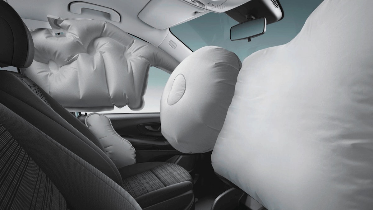
Automobile airbags are of lifesaving importance. Such airbags are triggered by an impact sensor, that is intended for detecting the acceleration signal in case of impact. The impact sensor monitors and controls the explosion of the airbag executed by an electronic control unit (ECU) cell.
To function correctly the car bodywork at the mounting position must have sufficient stiffness - the frequency response must be restrained within a critical range. At SAIC Motor the acceleration and frequency response (inertance) are measured and analyzed online using DewesoftX software and DAQ devices.
Introduction
Such inertance measurements are made in order to avert malfunction explosion and avoid unnecessary hazards and costs. The results are commonly verified complying with criteria set by Continental AG, as the CAE simulation-based methodology cannot replace the real condition testing. When the internal reason for resonance is determined, it may guide further modification of the structures to improve the stiffness of bodywork and chassis.
Safety is the priority of modern automotive development, where airbags play a key role to protect drivers. The controller of airbags, ECU functions rapidly to trigger the airbag for passenger protection as soon as it detects severe collision that exceeds the restraining capability of the safety belt.
Instead, the airbags also hurt passengers severely in case it explodes under minor accidental collisions. As a result, it is critical for the car manufacturer to ensure that the ECU mounting bracket and vehicle bodywork can be working with enough stiffness to resist a certain level of impact.
The success story comes from Shanghai Automotive Industrial Corp. (SAIC Motor), which is the largest auto manufacturer in China's market. SAIC Motor's business covers the research, production, and sales of both passenger and commercial vehicles and is also engaged in the R & D, production, and sales of auto parts. SAIC Motor's affiliated OEMs include:
SAIC Passenger Vehicle Branch,
SAIC Maxus,
SAIC Volkswagen,
SAIC General Motors,
SAIC-IVECO, etc.
In this case, we are working with the Safety Engineering & Virtual Technology Dept. (SMTC) of SAIC, who is responsible for resonance test (inertance) complying with the Continental Resonance Test Method and Judge principle. With our award-winning Dewesoft DAQ solution the customers are able to implement resonance tests by themselves.
Dewesoft core philosophy is one software for all applications! DewesoftX data acquisition software is the result of this philosophy. We have been implementing countless features for Automotive, Power analysis, NVH, Aerospace, Industrial, Civil engineering applications, as well as features for general test and measurement. Data recording, analysis, reporting, and everything in between are covered within a single software solution.
Dewesoft features in this case an intuitive turn-key FFT analyzer for NVH tasks based on its versatile SIRIUS® USB data acquisition system. It may greatly save money and time for SAIC with no help from Continental engineers.
Issue and application
The function of an airbag impact sensor is to detect the acceleration signal in impact, which can be used for judging and controlling the explosion of the airbag by SDM. As to avert the airbag error explosion and avoid unnecessary loss, the sensor fixing point inertance must be restrained in the required range.
Industries / applications
The resonance test is defined as Inertance. The inertance provides a value that stands for the local stiffness at the ECU/G-SAT mounting position, which is important for the acceleration signal quality.
The inertance can always be understood as the ratio of the signal output to input (amplification or damping factor). The calculation of inertance is:
Where Ax, Ay, Az represents the acceleration of x, y, z-direction, and F is the hammer force. The unit of inertance is g/N.
The resonance test and judge principle were initially released by Continental AG. In general, the inertance falling into the yellow and green zone is acceptable.


With the development of the Continental algorithm, the following condition is also acceptable:
If inertance falls into the red zone above 600Hz, the result can be acceptable
If inertance falls into the red zone between 400 and 600Hz, and inertance<=2, the result is also acceptable. But if conditions allow, modification is needed.
Accordingly, the simulation resonance test (CAE) is always a more cost-effective way to validate preliminarily and CAE is also needed prior to the experimental test.
The input signal is 0-2000Hz sine wave amplitude of 2g for the whole band, and the band step is 10Hz. The output is injecting sine waves for ECU in the single direction, and collecting the signal output of X, Y, and Z direction. The non-injection direction signal’s strength should be less than 20% of the injected signal. And the required direction signal’s strength should be similar to the injected signal (80%-120%).
For example, inject a 2g signal in the Z direction for ECU, and the signal’s strength for the X and Y direction should less than 0.4g (2g*20%). But the signal’s strength for Z-direction should be 1.6-2.4g.
To be sure, the CAE result cannot replace the real condition resonance test. It is just for reference, sometimes the result may be different from the resonance test. Because the CAE model is an ideal model, the real condition may be worse or more difficult than it. It is common that the CAE result is acceptable, but the resonance test is not acceptable, or the CAE result is not acceptable, but the resonance test is acceptable.
The resonance test is supposed to comply with the Continental method while Continental provides test certification service. Now it’s also allowed by Continental that some customers have their own resonance equipment, and it is recommended to do this resonance test by customer-self.
Because it will save lots of time and money for both. But some requirements should be met and the resonance test result should be sent to Continental for analysis. The whole test process refers to the law and regulation including:
Continental Resonance Test Method and Judge principle – Continental AG
GB/T 37474-2019 Methods and requirements of airbag system abuse test for automobile
GB/T 19949.1 -2005 Hybrid electric vehicles – Power performance – Test method
The Dewesoft measurement solution
Measurement setup
The resonance test has been regularly carried out at SAIC’s workshop with no need for a road test on proving ground. The vehicle under test is a SAIC ROEWE RX5 SUV prototype.


The measurement system includes an impulse hammer, acceleration sensors, data acquisition unit, and power supply. All reference sensors should fulfill the following specification:
No sensor resonances in the measured frequency band (0-5000Hz)
Sensor mass less than 10g
Sensor dimension less than 1cm × 1cm
The sensor has been calibrated before the tests
The DAQ hardware requirements are:
Dewesoft SIRIUS DAQ system model SIRIUSi-8xACC is an 8-channel IEPE/voltage analog input data acquisition device
Dytran 5800B5 Dytranpulse Impulse Hammer is a general-purpose IEPE impulse hammer used to excite structures or machinery with a definable impulse force. The impulse is used to identify resonances, an important measurement parameter for the study.
Dytran 3333A3 accelerometer: a miniature IEPE triaxial accelerometer with low-end frequency response, for excellent phase response at low frequencies.
The data acquisition software required:


Inertance measurements
The end-user SAIC makes a slight improvement on Continental’s setup mounting a triaxial accelerometer instead of 3 single sensors to test X, Y, Z direction acceleration signal on the position of SDM (Supplemental Restraint System Diagnostic Module) and the bottom of the B-pillar of the vehicle.


The sensor cube can be directly glued to the screw head or nearby floor. And it’s preferred to use a specially designed gauge to guarantee the angle of the cube. The gauge will be removed prior to the test starts.


Workflow
The typical sample rate is 20kHz with an anti-aliasing filter of 4kHz.
For each position, at least 3 times a hammer hit about 50N to 100N is needed. Ensure hit duration as short as possible and without double clicking.
The complete sensor data, including 10ms of pre-trigger, should be recorded at least. It’s recommended to record the 500ms signal at a 20kHz sample rate.
The inertance measurement is very sensitive to electrical noise, for example, 50Hz from the power supply. It is recommended to record each 250ms pre and post-event to confirm whether there is electronic noise. A Hammer hit (approx. 20N) can be used as a trigger.
Data recording and format requirements
After each test, it is necessary to document the test position, test direction, the test setup, and all the relevant information to analyze or repeat the workflow. After each test, it is highly recommended to record the test description, test number, date, vehicle (VIN number), and test location.
All the test data should be checked directly after the test. The measured data should be 60-95% of the setting range. For all sensors, there should be no obvious noise signal before the hammer force.
In accordance with the up-to-date specification, it is also allowed to record 80ms data with a 50% pre-trigger. That can be easily implemented with the turn-key DewesoftX data acquisition software. We just set the threshold to 50N at a rising edge during the test and start acquisition at a sample rate of 25.6kHz, storing fast on the trigger.


Online calculations are needed to enable the SAIC engineer to be aware of the result the first time on site. The frequency-domain reference curve is such a sharp tool to get it done. The user has plotted the reference curve as a predefined mask.


The algorithm by Continental is to get all spectra of the 3 directions acceleration and force individually Figure 8-11, then inertance in the frequency domain is directly calculated. To maintain consistency, the users simply copy the algorithm having the spectra by Math Library in DewesoftX data acquisition software.


The spectra are operated by FFT Math with a frequency resolution of 12.5Hz. DewesoftX Formula Math is intuitive for users to edit formulas as to how inertance defines.


Test results
The measurement analysis can be visualized where the inertance spectrum is plotted on DewesoftX Visual Controller - 2D graph. For clear contrast, a predefined tolerance zone (reference curves) is overlapped on the graph as well - and the result is revealed.


For comparison and validation every test done by the user - the raw data (acceleration, force) - has also been sent to Continental for analysis. The authority’s evaluation results were consistent with ours – see figure 14. In this case, the test point (B-Pillar) as shown is good and will be deemed as qualified by the Continental company.
Generally, the ECU mounting bracket and the bottom of the B-Pillar are the two mandatory test points instructed by Continental where each point has an average of at least 3 hits. The engineer would also suggest that a hammer force applied of 20N to 60N could be enough based on a multiple test summary.
Conclusion
Continental reports accordingly that the experiment is done and the facility used by SAIC customers are approved. Therefore, Dewesoft will be listed as a standard unit for the test while Continental engineers will no longer travel to SAIC on-site afterward.
Alternatively, the raw data and analysis are required to be submitted to Continental authority for validation.
The solution can be widely popularized by car manufacturers since many of them have such requirements. For the resonance test, SIRIUS mini 4×ACC is definitely a basic solution, more economic in case the customer’s budget is limited.


SAIC is very pleased to accept Dewesoft quickly since they are not going to spend large amounts of money to ask Continental engineers to come. It obviously frees up a huge budget of the Safety Engineering & Virtual Technology Dept. every year.
Besides, as a versatile data acquisition system, the Dewesoft is going to be applied to sound measurement for SAIC as well as saving additional investment. The Dewesoft as a professional FFT spectrum analyzer has it all that includes top performance, advanced cursor functions, high freely selectable line resolution, flexible averaging, and advanced functions for in-depth frequency analysis.
Dewesoft is recognized as a very cost-effective solution for a wide range of automotive NVH tests. It is certainly such a sharp tool and is supposed to be widely accepted by plenty of automotive engineers.
Documentation and external resources
Continental Resonance Test Method and Judge principle – Continental AG
GB/T 37474-2019: Methods and requirements of airbag system abuse test for automobile
Zhang Li, Li Cuixia, Lei Yingfeng: Analysis and optimization of frequency response for airbag impact sensor fixing point.
Bian Xintao: Automobile safety airbag ECU resonance analysis.