


Using Dewesoft DAQ Hardware Under Intrinsic Safety Protocols

Grant Maloy Smith & Ryan Key, and Owen Maginity
December 8, 2023
What is intrinsic safety?
Intrinsic safety (IS) is a set of techniques and methodologies related to safely operating electrical equipment in hazardous areas, including those with explosive or flammable gasses. It is performed using electrical barriers and other IS accessories. These barriers limit the thermal and electrical energy in hazardous areas. Intrinsic safety is critical for reducing hazards to people and equipment. Tiny sparks from power switches, motor brushes, relays and electrical devices are common in normal environments and pose no risk. But in oxygen-rich and other atypical environments, they can become a source of ignition.
What defines a hazardous location?
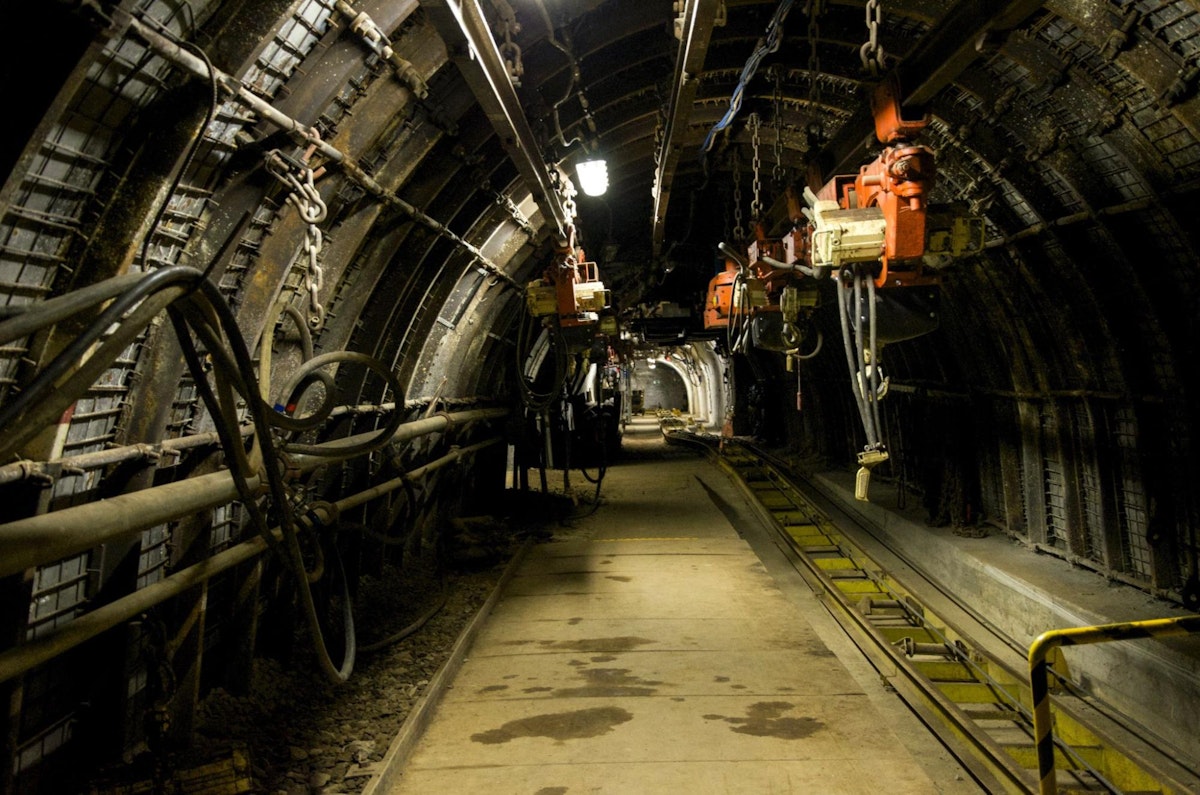
Locations that have concentrations of flammable gasses or dust include petrochemical refineries and mines. A hazardous location is defined as an area potentially containing explosive gas, vapor, dust, or fibers. To mitigate the risk of ignition, the deployment of low-power electrical equipment in these areas must be compliant with industry standards. Note that high-power equipment cannot be protected this way, and is not part of this discussion.
The National Fire Prevention Association (NFPA) publishes codes that define the requirements for safe area wiring in the United States. A hazardous location definition contains a class and a division. These refer to the type of explosive, and if an area could contain that explosive under normal operating conditions. They also define if the explosive potential could exist under accidental conditions.


The definitions are for areas that could contain:
Explosive gas/vapor (Class 1)
Dust (Class 2)
Fibers (Class 3)
They also define if those conditions exist under normal operations (Division 1) or under accidental release (Division 2).
The EU (European Union) has its standards related to intrinsic safety, Directive 2014/34/EU. The CENELEC standard IEC 60079-11 is certified according to the ATEX directive. Many other countries follow the IEC standards. However, there are numerous standards around the world, so it is important to follow the requirements at your location.
How to achieve compliance
Adherance to safety regulations must be taken before using electrical equipment in hazardous areas. Some equipment is certified by their manufacturers to operate in restricted areas according to various classes and divisions. These are collectively referred to as “intrinsically safe equipment” or “intrinsically safe systems.” An intrinsically safe circuit must be designed in such a way that it cannot cause ignition of the atmosphere due to a discharge of electrical or thermal energy. In addition, this risk must be defined for both normal and atypical work environment conditions.
These items include self-contained, battery-operated radios, and monitors for detecting explosive gas. These items are individually labeled to indicate to the user that they are safe to operate in hazardous environments.


Taken from a US Coast Guard informational page, the sample label above shows the typical format of electrical equipment markings. There are often several overlapping explosion protection techniques from the National Fire Protection Association (NFPA) 70, their National Electrical Code (NEC), and the International Electrotechnical Commission (IEC). It is beyond the scope of this article to define them all, but there is ample information available on those organizations’ websites.


Electrical equipment not certified to operate in those environments must be mounted in a safe (non-hazardous) area. Any connected wiring that enters the hazardous area must be routed through intrinsic safety barriers to ensure the wiring is non-incendive.
How to use equipment that isn’t intrinsically safe?
You can use non-certified instruments or equipment in these applications, but they must be located in a safe (non-hazardous) area. Additionally, they must be connected to equipment in the hazardous area via intrinsic safety barriers.
Because Dewesoft instruments are not intrinsically safe, they must be connected using safety barriers. We performed a series of tests to determine if measurement quality, response, or noise level would be impacted by the barriers. We chose the most sensitive amplifier that we make, the SIRIUS STG strain gage signal conditioner. Here are the results of our tests.
What is an intrinsic barrier?
An intrinsic barrier is a small passive device that provides isolation between safe and hazardous areas. Although barriers are often DIN rail-mounted, they don’t have to be. They are pass-thru devices with terminal blocks for their inputs and outputs on opposite sides.
The energy that passes through the barrier and enters the hazardous is limited by various combinations of diodes, resistors, zener barriers, and fuses. Barriers are also “polarized” in the sense that there is a hazardous location side and a safe (non-hazardous) location side.
Please note that intrinsic barriers represent only one element of an entire system that may be required to safely make measurements in areas where explosive or hazardous material may be present.


Breaking down the barriers
Key points about barriers:
No signals are needed for barriers to operate. They are “always on” in that sense.
As shown in Figure 3, barriers have a Hazardous side and a Non-Hazardous side (aka the Safe area)
In addition to passively reading sensor outputs, various Dewesoft amplifiers provide sensor power (aka “excitation”). These include strain gage amplifiers, IEPE amplifiers, voltage amplifiers (with DSUB and LEMO connectors), universal, and multi amplifiers.
It may require more than one barrier to handle a single signal conditioner. For example, three barriers are needed for a strain measurement because of the sheer number of connections that must be made. This includes quarter, half, and full bridge wiring from sensors like strain gages and load cells.


What is a compliant system?

 SIRIUS DAQ instrument (2) Test fixture")

 SIRIUS DAQ instrument (2) IS barrier (3) Test fixture")
Test fixture overview
Our test fixture consisted of a pneumatic double-acting cylinder, a pneumatic directional valve, a pneumatic regulator, an S-shaped load cell, a customized I beam, and various rigging components.


The Intrinsic Barriers (IS) were mounted on a DIN rail and wired via male/female connectors to a bridge-based sensor.
Let’s take a look at the components of our DAQ/Control system:


The DAQ/Control system consisted of:
SIRIUS 6xSTG 2xSTG+
KRYPTON 4xDO digital output module
KRYPTON-1xAO analog output module, and
DS-CAM-600c high-speed video camera.
Not shown: a Windows PC running DewesoftX DAQ software to control the tests and record all the data, including video. Numerous screenshots from the tests are included in the following sections of this report.


Cylinder direction and pressure were controlled by a pneumatic directional valve and a pneumatic regulator. Those components were controlled by two Dewesoft KRYPTON digital output channels and one KRYPTON analog output.
The system actively controlled the force either by setting a scaled singular setpoint or in “auto” mode. The auto feature was performed by DewesoftX software, which used the force measurement as feedback and collected user input for the setpoint using the built-in PID Math Tool.
Test fixture setup
As shown below, an “S” type load cell was used as the feedback for the regulator position during auto mode.

 pressure cylinder (2) fixturing (3) the carabiner UUT (4) the “S” type load cell that measured the force applied to the carabiner by the pressure cylinder")
Test overview
We conducted a series of tests using the Dewesoft measuring system. Half of the tests had a load cell connected directly to the SIRIUS-STG (strain gage) amplifier, and the other half were performed with a set of Intrinsic Safety Barriers between the SIRIUS-STG and the load cell. We did not change any settings or perform any software rescaling or hardware balancing when switching from using and not using the IS barrier. The point was to see if the barrier had any negative effects on the measurement.
The Cycling Test switched the load connected to the load cell between two different load values using both hazardous and safe wiring conventions.
The Tensile Load until Failure test loaded a give-way carabiner until failure. The test was conducted four times: twice with Hazardous Area and twice with Non-Hazardous Area wiring conventions, as shown below.
The failure tests
We conducted four tests wherein we applied tension to four carabiners until they failed. The test process consisted of increasing the pressure to 80 lbs via manual control, engaging Auto, and then increasing the setpoint of the regulator position in 5 lb increments until the test article failed.
Test 1
In the first test, no intrinsic barriers were used. Test Article 1 held a maximum load of 112.42 lbs of force.
Tests 2 and 3
In tests 2 and 3, the IS barrier was installed between the load cell and the Dewesoft strain gauge amplifier. No signal offset was measured and no re-scaling or re-zeroing was done. Test Article 2 held a maximum load of 117.88 lbs of force, and Test Article 3 held a maximum load of 132.52 lbs.
Test 4
In test 4 the IS barriers were removed from the circuit and connected the load cell directly to channel 1 on the SIRIUS unit. Test article 4 held a maximum load of 117.76 lbs-force.
What did we learn?
During testing, adding or removing the IS barriers did not affect the quality of the measured data. The noise, gain, offset, and frequency response were completely unaffected. In addition, the use of IS barriers did not require any adjustments to the scale, offset, or balancing settings.
In summary, we can report that Dewesoft instruments can be used in these applications with no loss of accuracy or convenience.
Legal disclaimer
Dewesoft is not responsible for damage, injuries, or death resulting from experimentation with intrinsic safety. Always hire professionals trained and certified in intrinsic safety work before attempting to use any non-certified equipment in a hazardous area.