


Two-plane Balancing on a Harvester Rotor
Rok Podjed (student)
University of Ljubljana
October 24, 2023
Rotors have been part of human history since the invention of the wheel. Today, rotors are in most machines and tools available. Balanced rotors are essential for all kinds of rotating machinery. An imbalance will create high vibrations, reducing the machine’s lifetime and causing fatigue and material defects. In most cases, the rotor imbalance is the major vibration problem, and it is related to the rotational frequency.
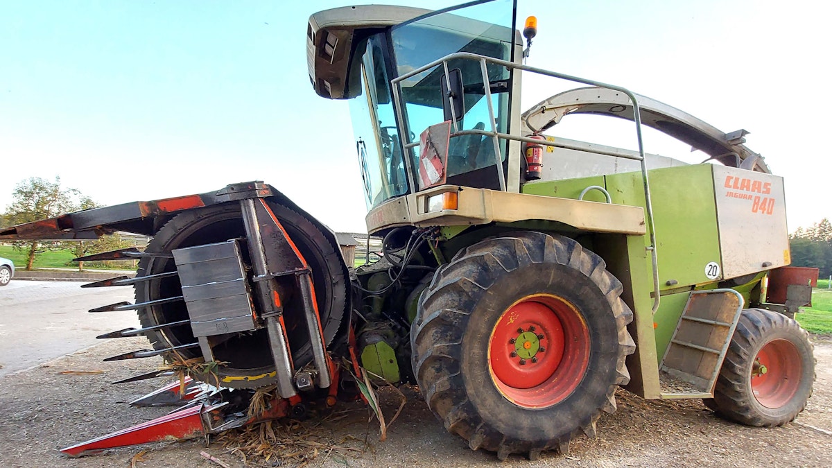
I did some experiments on a forage harvester. This agricultural machine can cut forages, like corn, grass, or hay. The forage harvester can be attached to a tractor or be self-propelled. It has a rotor with several knives fixed to it that chops and blows the harvested green crop out of a chute of the harvester into a wagon. The fermented crops provide fodder for livestock as silage.


A rotor can be mass unbalanced for several reasons, such as:
Operating accidents,
Asymmetric rotor wear,
Mechanical vibrations,
Mass changes,
Distorted bearings,
Thermal effects,
Imprecise manufacturing, etc.
The goal of balancing is to minimize vibrations related to the first order. When performing on-site balancing, I did not need to disrupt any other machine parts but simply measured the vibrations at the bearing points.
When balancing the rotor, I aim to ensure that the rotor does not vibrate at operating speed.
Depending on the machinery, single or dual-plane balancing is used. In general, selecting one-plane or two-plane balancing depends on two factors. One of the factors is the ratio of the length of the rotor (L) to the diameter of the rotor (D). The other factor is the operating speed of the rotor. As a general rule of thumb, I refer to the table below.
| L/D Ratio | Single Plane | Two Plane |
|---|---|---|
| Less than 0.5 | 0 - 1000 RPM | Above 1000 RPM |
| More than 0.5 | 0 - 500 RPM | Above 500 RPM |
Measuring equipment
DEWE-43 A: An 8-channel data acquisition system.
Two IEPE accelerometers for dual-plane balancing.
One digital tachometer.
DewesofX: data acquisition software bundled with DEWE-43A.
Balancing option: DewesoftX add-on for single- and dual-plane balancing.


Measurement procedure
When attaching the equipment, I must do it accurately, as a poor attachment can lead to errors in the measurement.
The accelerometer should be fixed to the bearing housing with the help of a second adhesive to ensure good contact between the bearing housing and the accelerometer.


I positioned the tachometer using a magnetic holder. I set it to read the revolutions on the end of the rotor, the pulley. I could have placed it elsewhere, but the important thing is that the tachometer reads the rotor revolutions accurately.


Once I have set up the equipment, and connected the DEWE-43A data acquisition system to the computer, I can start setting up the measurement in DewesoftX software.


When setting the accelerometer, pay attention to the settings found in the analog tab. The settings can be done automatically via transducer electronic datasheets (TEDS) or manually. In the manual settings, you must select the sensor type.
In my case, this was an accelerometer which measured the gravitational acceleration in g’s. In the sensitivity box, I must enter the correct sensitivity value from the accelerometer. The accelerometer sensitivity can be found on the accelerometer box or online.


I connect the tachometer to the counter/digital input module - see Figure 7.


I opened the counters tab and then the settings for the channel to which I connected the tachometer. In the software, I set the sensor type, which I have connected to the channel - see the tachometer settings in Figure 8.


Once I have connected all the sensors and all the settings have been configured, I have enabled the rotor balancing module in DewesoftX software.


I select dual planes and enter the approximate rotational speed of the rotor.


Within the frequency channel settings tab, I choose the counter, and in the frequency-channel box, the input to which the digital tachometer is connected. In the sensor box, I select the type of sensor in use, in my case, the digital tachometer.


After completion of the software setup, everything is ready for the measurement. Now I need to attach the measuring equipment.
Balancing procedure in Dewesoft
The single-plane or dual-plane balancing procedures differ depending on the option I select. The following steps have to be taken in the procedure:
Initial run,
Trial run(s), and
Correction run(s).
I started the rotor and recorded the accelerations at both bearing positions for my initial measurement. The results are displayed graphically in the software - see Figure 12.


In my trial runs, I had to attach the test mass to the rotor. For the first measurement, I added test mass to one side of the rotor near the bearing, where I had an accelerometer connected to channel 1.
For the second measurement, I placed the test mass on the other side of the rotor, also close to the bearing. It is important to remember the location of the test mass, and I will explain more at the end.
The weight is arbitrary, but I need to know exactly how much mass I added to the rotor. In the software, I press the button in the top right corner, and a new window appears, asking me to enter the weight of the test mass. In my example, I have added 200g of test mass.


The picture below shows how I attached my test mass using a bolt with a nut and a washer.


Once I have entered the weight of the test mass into the program, I press the next button again to return to the previous window. I can now rotate the rotor again and measure the accelerations at the bearing points.


I repeat this process for the rotor’s other side, attaching the test mass and measuring the accelerations at the bearings.


Once all three measurements, the initial, 1st trial, and 2nd trial, are done, the software has obtained the graphical results. Figure 17 shows my balancing results.

Conclusion
There are two methods I can use for balancing. One is to add mass to the rotor, and the other is to remove rotor mass. In this case, I chose to add some mass.
The software tells me that on the first plane, I should indicate the mass, which weighs 110.4 grams, to 278 degrees according to the test mass setting. On the second plane, I needed to place a mass weighing 183.5 grams on 324.5 degrees. I could not put the masses in the required positions because that’s where the rotor knives were. So, I divided the mass into two, considering the relationship between the mass placement and the desired position.
After completing the procedure, I again measured the accelerations at the bearing points to check that I had sufficiently reduced the vibrations. I obtained the results in Figure 18. The figure shows that the acceleration reduction was sufficient. That indicates that I had balanced the rotor well. Had the reduction been insufficient, I would have to repeat the balancing process.

