


Tractor ADAS Testing - Vulnerable Road User (VRU) Detection
Marco Pesce, Automotive Applications Senior Specialist, Leane International Srl
National Research Centre for Agriculture (CREA)
May 7, 2024
Advanced driver assistance systems (ADAS) have spread far in passenger cars, light commercial vehicles, and heavy trucks. What’s less known is that manufacturers also apply ADAS systems on moving agriculture machines. The so-called ‘fast tractors’ running faster than 60 km/h introduce a demand for active safety systems like ABS and vehicle stability control. LEANE used Dewesoft DAQ hardware and software to calculate parameters like distance, position, and angle in ADAS testing.
The term Vulnerable Road User (VRU) is mainly used to describe people in the range of vehicles unprotected by an outside shield - on the open road or in the field. VRUs include pedestrians, cyclists, and other non-motorized road users having a greater risk of injury in a collision.
The engineering company Leane has been in the Italian market for around 50 years. Since 1978, its Automotive Division has provided its customers with turnkey solutions for vehicle data acquisition. With years of experience and highly specialized engineering expertise, Leane supports customers from the sensor choice to the final report. The company offers standalone devices and the capacity to build fully tailored solutions to customer applications, from the single sensor to a complete turnkey measurement system, from road testing to a driving simulator.
Manufacturers of agricultural machinery, such as tractors and the countless kinds of farm implements that they tow or operate, are working to deploy the following ADAS systems to improve VRU protection:
Blind Spot Monitoring (BSM)
Blind Spot Information System (BSIS)
Moving Off Information Signal (MOIS)
Many stakeholders, including OEMs, tier 1 suppliers, and insurance companies, promote actions and projects to increase safety and shape future regulations.
The application
The National Research Centre for Agriculture (CREA) is responsible for one such initiative. CREA is dedicated to agri-food supply chains and is OECD-accredited to certify agricultural and forestry tractors.
The center initiated a preliminary test campaign at the end of 2023, focused on Vulnerable Road User (VRU) detection in the agricultural tractors passing and surrounding a pedestrian dummy. Among the critical challenges in this kind of application in the agriculture context are issues such as:
The tractor configuration may vary a lot: different working tasks require various implements fitted on the tractor, which affects the human operator's field of view and the sensors’ range in varying ways.
The machinery operates in different scenarios: on the road, in the courtyard for material handling, in the field, or among trees. Within their operation range, the machines can encounter VRUs and objects of many different shapes.
The first session allowed a few suppliers and universities to show the potential of their camera-based or radar-based solutions for VRU and obstacle detection fitted on production tractors. They demonstrated the capability to detect a pedestrian dummy without implementing an onboard control system integration.
At this stage, the goal was to perform some simple scenarios. The tests took place on a clean asphalt surface, with the tractors approaching a static pedestrian dummy with different trajectories at different angles.
An Inertial Navigation System (INS) with DGNSS Real-time Kinematics (RTK) was used as a ground truth reference to obtain the precise absolute position of the dummy and its relative distance to the tractor to verify the detection system's performance.
Future test sessions will be planned, with more complex scenarios in which driving robots and robotic VRU carrier platforms perform.
The test scenario
We set up the test scenarios on the asphalt track at the CREA proving ground. This area consists of an oval with a central square that can serve as an intersection or to perform cornering maneuvers at moderate speed.
We carried out two cases of testing, scenarios A and B:
A) The pedestrian dummy is at a corner while the tractor moves within the corner at different speeds and paths (inside/outside) - see Figure 8.
B) The pedestrian dummy is on the straight while the tractor travels at different speeds and lateral offsets along the straight - see Figure 9.
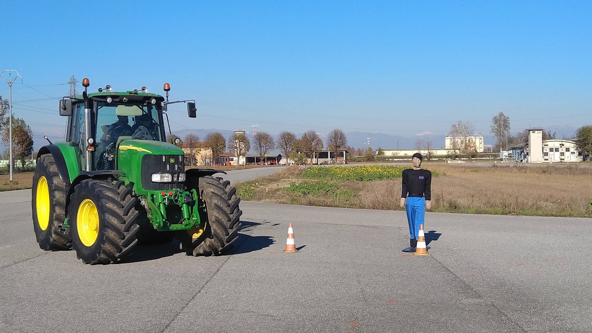
The engineers placed the pedestrian target at RefPoint1 for test scenario A and RefPoint2 for scenario B - see Figures 1 and 2.


The track view below shows the dummy placed at RefPoint2 and some cones used to mark the paths for the test cases.


The test equipment
The equipment used for testing included:
Static pedestrian adult dummy MoshonData MD-PT
Inertial Navigation System (INS) - Genesys ADMA Speed with RTK via NTRIP
Dewesoft DEWE-43A data acquisition system
USB web camera
Laptop with DewesoftX data acquisition software with Ethernet Receiver and Polygon extensions
The system setup (Figures 3 and 4) also included an Ethernet sniffer with simple filtering capabilities and data decoding to extract data channels from Ethernet streams. The sniffer allows stream filtering by parameters such as MAC and IP address, source and destination port, or manual data filters. It can encode data in different formats (Intel, Motorola, signed, unsigned). Both IEEE floatLinear and IEEE non-linear (polynomial) scalings are possible.
The DewesoftX Polygon plugin is a tool for calculating parameters such as distance, position, or angle between moving or static objects such as cars, cones, tracks, or lines.
The plugin can be the base for any autonomous or non-autonomous vehicle tests, such as:
Autonomous emergency braking (AEB)
Lane change
Lane departure warning (LDW)
Circle drive
Slalom
Collision warning
Performance test
Pass-by noise
Functional safety tests
Vehicle dynamics
and others
It also provides track import from previously recorded files with up to 1cm accuracy and fully adjustable 3D visualization for easy data analysis and real-time driver guidance.
The list does not include the prototype equipment, i.e., the radar-based or camera-based detection systems, and due to confidentiality issues, we cannot share the acquired signals.


Dewesoft setup
In this case, the DEWE-43A data acquisition system captured the data from the CAN bus, as we didn’t install analog sensors on the tractor.
For convenience, we installed the Genesys ADMA Speed sensor on the top of the cabin, right above the driver’s head. In addition, we then configured the ADMA to output the measurement data at the PointOfInterest1 (POI1), set at the center-front of the tractor. An NTRIP DGNSS service provided RTK data that ensured centimetre-level accuracy of the absolute position of the tractor.
The Ethernet receiver plugin captured the data stream from the ADMA.
The DewesoftX Polygon plugin provided a 3D representation of the operation field. The software also calculated the channels supplying information about the tractor's relative position to the static dummy, i.e., ReferencePoint1 and ReferencePoint2.
For convenience, we set the coordinate system at ReferencePoint2 with the X-axis in the straight direction. By doing so, the coordinates of ReferencePoint2 - where the dummy was for the test scenario B - match those.
Then, we set the coordinates of ReferencePoint1, referring to the coordinates POI1, when the front of the tractor was close to the dummy at ReferencePoint1 - see Figure 5.


After this, we added a few calculated channels to get the distance along X, Y, and the relative distance:
From the driver’s head to the dummy locations at ReferencePoints 1 and 2.
From the front of the tractor (POI1) to the dummy locations at ReferencePoints 1 and 2.
Furthermore, we included three tractor movement circles, having radii of 3m, 6m, and 12m, with their centers at the driver’s head coordinates. We chose the value of 12m based on the preliminary requirements of the draft testing protocol.
We added the DirectX USB camera to provide a simultaneous view of the scene from the tractor cabin, as shown in the screenshot of the DewesoftX measurement display (Figures 6 and 7).


Test execution and results
We did several test runs with the tractor, approaching the dummy and stopping close to it or driving on a path aside from it. We also performed additional tests by performing obstacle avoidance maneuvers or driving the tractor around the scene to check how the prototype detection systems saw the dummy.
We are not allowed to show data from these detection systems. Still, thanks to the Polygon virtual geometries and DewesoftX math channels, we observed when the tractor approached the dummy's location and detected when it got inside the 12m, 6m, and 3m boundaries.


Conclusion
Combining positioning data with data from the test vehicle, cameras, and other sensors is a typical requirement of any ADAS measurement application.
Using the DewesoftX software, we could integrate all these data sources, quickly and easily adding online relative distance calculations and an effective 3D visualization by leveraging the Polygon extension plugin.
The DewesoftX Polygon module allows setting a local coordinate system to map the position of static objects on the track and track the Vehicle Under Test and other moving objects. The setup for this application was done directly on the track before the test in just a few minutes.
Another feature of Polygon is the possibility of creating geometrical entities linked to static or moving objects and using these entities for calculation and visualization, e.g., checking if a given object is within a given range from another object.
Based on the above facts, the customer decided to apply DewesoftX and Polygon for upcoming testing activities in this field of research.