


How Did They Do It? Testing the Saturn V Rocket

June 22, 2023
Introduction
Saturn V was the largest and most powerful rocket ever built. It was standing at 363 feet (111 meters) tall with a total mass of about 6.5 million pounds (2.9 million kilograms) at liftoff. That’s about the height of a 36-story-tall building, and the weight of 400 elephants.


The Saturn V heavy-lift rocket played a pivotal role in the Apollo Moon missions, propelling all six manned missions to the Moon, including the first lunar landing in 1969. As of 2023, it remains the only rocket to have carried humans beyond near Earth orbit. A two-stage version was used to launch the Skylab space station in 1973 – that was the last Saturn V that ever flew. A few hours later, a Saturn 1B rocket was also used to launch a smaller section of Skylab into orbit. The Saturn V was developed at NASA's Marshall Space Flight Center, located in Huntsville, Alabama, in America’s southeast.
In addition to five powerful F-1 engines, Saturn V’s technological advancements included a multi-stage design and complex guidance and control systems. The combination of so many groundbreaking technologies in a single, mission-critical vehicle required a testing regiment that was at least equally complex and rigorous. Accordingly, NASA engineers developed a comprehensive testing program to ensure its reliability and performance.
Saturn V was an enormous undertaking, far too big for any single company to handle. So NASA contracted out the work to the best and biggest American aerospace companies, naming them as prime contractors. There were dozens of secondary contractors and hundreds of smaller ones involved. In all, 20 thousand companies and approximately half a million people worked on the Saturn V and Apollo programs during the 1960s and 1970s.
Prime contractor Boeing was contracted to build the first stage (S-IC) of the Saturn V rocket, while the second stage (S-II) was assigned to North American Aviation. Douglas Aircraft Company built the third stage (S-IVB), and IBM designed and built the instrument ring that contained the computers, guidance systems and more.
The enormous F-1 rocket engines of the first stage as well as the J-2 engines of the second stage were built by Rocketdyne. Each F-1 engine measured 19 x 12.5 feet (5.8 x 3.81 meters) at the nozzle exit. They burned 15 tons of liquid oxygen and kerosene every second. During launch, the F-1 propulsion system produced 34.5 million Newtons (7.6 million pounds) of thrust.
North American Aviation also built the Apollo command and service module, while Grumman designed and built the lunar module. It was up to NASA to manage all of these separate tasks and integrate them into a single spacecraft capable of handling the entire mission.


Former German scientist Wernher von Braun had been secretly brought into the US Army after World War II to help design America’s ballistic missiles and rockets for launching satellites. His group was merged into NASA in 1960, and he was named the director of NASA’s Marshall Space Flight Center located in Huntsville, Alabama. He remained director until 1970, overseeing the development of the Apollo program and America’s successful Apollo XI moon landing in the Summer of 1969 when human beings first set foot on the moon.
These key testing methods and procedures were used for the Saturn V rocket:
Static Firing Tests
Stage Separation Tests
Dynamic Tests
Apollo-Saturn V Test Flights
Wind Tunnel Testing
Static firing tests
To validate the performance of the Saturn V's engines, a series of static firing tests were conducted. In a hot fire static test, the rocket is attached to a launching platform so that it cannot fly. Then the engines are ignited, and measurements are made of engine performance.
The rocket's first stage, known as the S-IC stage, was first test-fired in 1965 at the Marshall Space Flight Center in Alabama, where it had been developed. NASA used F-1 engines that were not intended for flight, doing exhaustive testing for months.


Later, testing of the first and second-stage engines was moved to the newly built “Mississippi Test Facility,” known today as NASA’s Stennis Space Center. Incidentally, during the 1970s and 1980s, Stennis also tested the US Space Shuttle Engines. More recently Stennis has tested the SLS (space launch system) engines for NASA’s Artemis space program.

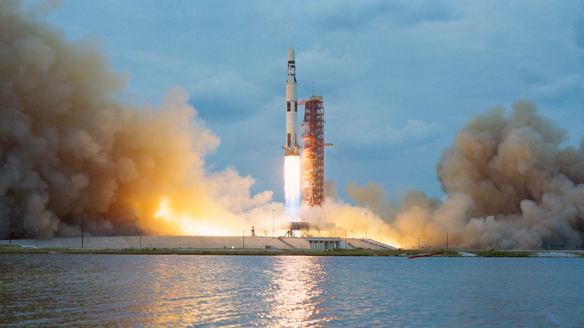
 and Liquid Oxygen (LOX), five Rocketdyne F-1 rocket engines produced 1.5 million pounds of thrust at liftoff. Photo courtesy Grant Maloy Smith")
During these hot fire static tests, sensors were connected to all parts of the rocket, and more than 1200 measurements were transmitted to the recording instruments in the blockhouse. Data was captured by computers and then formatted for recording on magnetic tape as well as on strip chart recorders, which allowed real-time graphical viewing of the sensor data. In addition to simply firing the engines, the engines were gimbaled (swivelled on several axes) in order to test their ability to steer the rocket during flight.
Stage separation tests
By combining ground-based testing, unmanned flight tests, and live missions, NASA ensured that the stage separation of the Saturn V rocket was thoroughly evaluated and validated. These tests involved firing explosive charges to simulate the separation events and ensure that the stages separated cleanly and without any structural problems.
Stage separation was a complex process that had to happen with precise timing in order to work safely. IBM’s instrumentation ring located above the third stage was the “brains“ of Saturn V. Pyrotechnics, aka “EBW (explosive bridge wire) firing units” were used to sever each stage and interstage ring from the spacecraft when their job was completed.
Smaller “ullage” rockets located on the stage above would fire long enough to provide the acceleration needed to ensure the smooth flow of fuel and ignite the next stage. Simultaneously, retro rockets on the spent stage burned for long enough to slow it down, increasing the separation distance from the rest of the rocket.
There was also an interstage ring between the first and second stages that had to be severed and cast off, all again with precise timing and movement to avoid damage to the spacecraft from debris or collision.


It should be noted that NASA launched ten of the smaller Saturn I spacecraft over a four-year period as a testbed for the technologies required by the moon-capable Saturn V. The Saturn I and uprated Saturn IB rocket launches helped NASA to perfect the liquid fuel dynamics and the multi-stage design required by the larger Saturn V rocket.
Following these tests, NASA launched the Apollo 4 (AS-501) and Apollo 6 (AS-502) unmanned missions in order to test Saturn V's launch vehicle and its three stages. During these flights, sensors and instrumentation were used to monitor and record data on the behaviour of the rocket stages during separation.
Dynamic tests
Dynamic tests were performed to evaluate the structural integrity of the Saturn V under the intense vibrations and shocks experienced during launch. The rocket was subjected to vibration modes that simulated the conditions it would encounter during liftoff and flight, to ensure that it could withstand the stresses and vibrations without any structural failures. Shocks were induced to simulate the pyrotechnic effect of exploding bolts used to ensure stage separation.
NASA engineers subjected the Saturn V rocket to comprehensive modal, sinusoidal, random vibration, and pyrotechnic shock tests, gaining critical insights into its structural behaviour and weaknesses. The data obtained from these tests guided design refinements and allowed for the necessary modifications to ensure the rocket's structural integrity during the intense vibrations experienced during launch and ascent.
The Saturn 500F was a full-size test version of the Saturn V that was not intended to be launched. It was a complete rocket, however, so it could be used for any test except actual flight. In fact, the Saturn 500F was sitting on the launchpad at the Kennedy Space Center in June 1966 when Hurricane Alma passed very close by.
Perhaps because of this close call, NASA decided to see how Saturn V would handle high winds, so they rolled it back into the VAB (vehicle assembly building) at the usual rate of 1 MPH (1.6 KPH), and decided to shake it. But how? There were no mechanisms that could do this, so in typical NASA fashion they found a unique solution: they employed human strength.
Dozens of NASA personnel pushed with their legs at the base of the vehicle while men at the top pulled on a rope to induce the enormous structure to teeter on its base, thus revealing its natural frequencies. Measurements were made to ensure that these kinds of mechanical inputs wouldn’t topple the Saturn V if it were on the launch pad during very high winds.
In fact, a large piece of the astronaut escape structure at the very top of the spacecraft fell off during the shake test, but no one was harmed.
By 1970 NASA was using scale models of the Saturn V to perform modal analysis. One such series of investigations were done at NASA’s Langley Research Center, where a 1/10 scale model was used to perform free-fall lateral vibration analyses.


Apollo-Saturn V test flights
Prior to the actual Apollo lunar missions, the Saturn V rocket was flown on uncrewed test flights known as the Apollo-Saturn V (AS) missions. These missions included Apollo 4 (AS-501), Apollo 6 (AS-502), and the final test flight, Apollo 8 (AS-503). These flights allowed NASA to test the Saturn V's performance in an operational environment before putting astronauts into the spacecraft.


Wind tunnel testing
NASA’s Marshall Space Flight Center built a stainless steel model of the Saturn V rocket to be used in wind tunnel testing. Just as aircraft, cars and trucks are subjected to wind tunnel testing to evaluate their aerodynamic characteristics, spacecraft must move through the atmosphere before reaching the vacuum of space. The model measured 426.7 x 54.6 cm (14 ft. x 21.5 inches), and weighed 362.9 kg (800 pounds).
Tests were performed at the Hypervelocity Ballistic Range G at Arnold Air Force Base in 1967. Wind tunnel tests were done to simulate reentry conditions as well. These series of wind tunnel tests revealed certain base heating problems that resulted in changes to the turbine exhaust ports.


Instrumentation and data collection
The instrumentation ring of Saturn V was located between the third stage and the Apollo service and command modules. This ring contained the guidance system as well as a digital computer, an analog flight control computer, EDS (emergency detection systems), a stable inertial platform with accelerometers and gyros, RADAR, radio command, power, telemetry, and other important subsystems.
The Saturn V rocket was instrumented with hundreds of sensors that monitored acceleration, temperatures, pressures, and vibrations. Sensors were critical components of the EDS because they could sense when physical parameters deviated from their optimal readings. Sensor outputs could also be telemetered to the ground, if necessary.


Telemetry, tape, and chart recorders
The word “telemetry” is a combination of the Greek root words “tele” (far or remote) and “metron” (to measure). Therefore, making a measurement and then sending it to a remote client is telemetry. This process was used to send approximately 200 parameters from the Saturn V to NASA before and during each mission, and during testing. Telemetry was needed for pre-launch checkout, command verification, mission monitoring and post-mission analysis. NASA needed to be able to monitor the spaceship’s acceleration, angular velocity, fuel flow rate, position, pressure, temperature, voltage, current, frequency, and other important parameters during all phases of the mission.
The instrumentation ring contained four measurement racks, each of which contained 20 signal conditioners. These signal conditioners were used to take raw sensor readings and convert them into useful engineering units. Signals were digitized and then routed to the appropriate channel in the telemetry data stream.
NASA used two telemetry links in order to handle the 200 measurement channels. Because broadcast bandwidth was limited, the data were multiplexed using both PCM/FM (pulse-code modulation/frequency modulation) and FM/FM techniques. The data was received by an array of tracking stations located around the globe. Regardless of the position of the earth, at least one station would receive it, and then retransmit it to NASA mission control in Houston, Texas.
Data was typically stored on instrumentation tape recorders. If NASA engineers wanted to view this data in real-time, it could be routed through DAQs (Digital to Analog Converters) and then routed to the analog inputs of large format strip chart recorders. NASA had hundreds of these paper recorders at its facilities around the USA.

, instrumentation tape recorder (right), and a Honeywell strip chart recorder (left). Image courtesy of Popular Mechanics")
Numerous strip chart, drum and event recorders were used by NASA, including Honeywell slow and high-speed recorders, such as light beam oscillographs, 200-channel event recorders, and Brush/Gould 8-channel large format oscillographic strip chart recorders, many of which were located right in the firing room for observation during and after launch.


Teledyne Helicorder RV-30H “paper drum” recorders were used for long-duration seismic data recording.

 using drum seismometer recorders. Photo courtesy of NASA")


Systems integration tests
The Saturn V underwent extensive systems integration testing to ensure that all components and systems functioned harmoniously. Various tests were conducted to assess the rocket's electrical systems, propellant loading, communication systems, and other subsystems, both individually and in combination.


First, each of the stages: the S-IC (first stage), S-II (second stage), and S-IVB (third stage), were tested thoroughly to verify the operation of its main systems, including propulsion, guidance, control, electrical, and instrumentation.
After the assembly of all three stages in the VAB at Kennedy Space Center in Florida, stage-to-stage testing was performed, checking the alignment and compatibility of the electrical and mechanical interfaces between stages, including fuel and electrical connections, avionics interfaces, and separation mechanisms. Countdown and launch sequences were simulated to validate the coordination and sequencing of all relevant systems.

 at the Kennedy Space Center on February 1, 1968. Photo courtesy of NASA.")
Post-flight analysis
After each test flight, a detailed post-flight analysis was conducted to evaluate the performance of the rocket and identify any anomalies or areas for improvement. This analysis involved studying telemetry data, inspecting recovered components, and debriefing the astronauts and mission specialists. All of this data was compared with the overall mission objectives. Lessons learned were applied to the next mission, with the goal of continuous improvement.
By subjecting the Saturn V rocket to these rigorous testing procedures, NASA was able to verify its performance, validate its systems, and address any fit, performance or reliability issues that were discovered. NASA’s testing program was critical to the success of the Apollo program, and the safety of the astronauts.
The legacy of the Saturn V extends beyond its Moon missions. It laid the foundation for future space exploration programs and technologies, and its lessons continue to inform the design of current and future rockets.
The Saturn V stands as an enduring symbol of humanity's ability to explore and reach new frontiers. It represents the heights we can achieve through ambition, innovation, and the spirit of exploration.
 tall and take 45 minutes to fully open or close. 2013 photo by Grant Maloy Smith.")
References
Non-flight-rated F-1 engines tested at NASA Marshall Space Flight Center
Flight-rated F-1 engines tested at NASA Stennis Space Center
Watch a Saturn V First Stage Test Firing! | Historic Video (YouTube)
Apollo 4 & 6: First Saturn V Test Flights - Historical Footage, 1967, A-type missions, CSM, NASA
How NASA Built The Rocket That Went To The Moon | The Saturn V Story | Spark
Power for Apollo Saturn V - Remastered NASA documentary - Engine tests and rocket development
To the Moon: Boeing, the builder of the mighty Saturn V Apollo rocket