


Testing the Reliability of Automated Greenhouse Doors
Matej Kotnik
Faculty of Organizational Sciences Kranj, University of Ljubljana
July 15, 2025
In modern horticulture, controlling the microclimate is crucial to successful plant cultivation. One of the critical factors is proper ventilation of the greenhouse, as it allows for temperature and humidity regulation and prevents overheating. In this project, I developed an automated system that opens and closes greenhouse doors based on temperature. I then analyzed its operation and reliability using the Dewesoft DEWE-43A data acquisition system.
The automatic door system
A greenhouse microclimate can be manipulated by control actions, such as heating, ventilation, and carbon dioxide enrichment, to provide appropriate environmental conditions for its plants.
Automatic doors, often paired with ventilation systems, are crucial for maintaining a stable microclimate and optimizing plant growth. These systems automatically adjust based on temperature and other environmental factors, regulating temperature, humidity, and airflow to create the ideal conditions for plants.


The measured automatic door system operates through an Arduino microcontroller combined with an ESP8266 WiFi microchip for wireless connectivity. A DC motor, controlled via relays for direction selection and a MOSFET transistor for power regulation, operates the doors. Measuring the current flowing through the motor controls the load. A 12V power supply that includes current protection powers the system.


Issue, objectives, and equipment
The primary purpose of the measurements is to verify whether the door reliably responds to temperature changes and whether its movement is mechanically flawless. The results will help identify potential hidden errors in the program logic and contribute to increased system reliability.
Data acquisition and test conditions
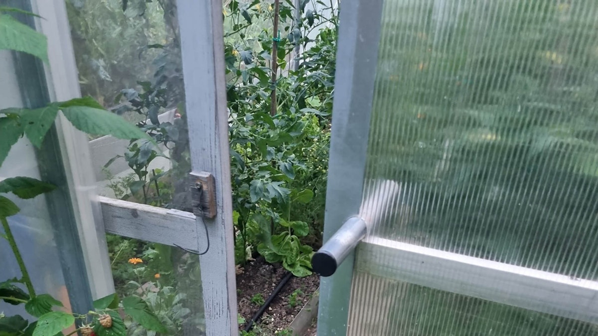
I installed the measuring system in the greenhouse. For data acquisition, I used a Dewesoft DEWE-43A, an 8-channel USB data acquisition system, equipped with the following sensors and installed at selected points:
Thermocouple (Type K)
In the shade inside the greenhouse for temperature measurement
Current meter/Shunt resistor
On the motor cable for monitoring the motor load
Rotary encoder
Along the door, guides for precise monitoring of the door position.Piezo accelerometer
On the motor bracket for detecting vibrations during collisions or door shocks


I performed the measurements with a sampling rate of 20 kHz. I monitored events such as automatic opening and closing, manual intervention, and obstacles under the door.


To perform the measurements as practically as possible, I connected the DEWE-43A to a Raspberry Pi, a low-cost, credit-card-sized computer suited for a wide range of projects. In this case, it acts as a USB server with the VirtualHere service.
Traditionally, using USB devices requires direct connection to a computer. With VirtualHere, the network itself becomes the cable transmitting USB signals. This feature enables me to remotely monitor the measuring system's operation from a PC in my room.
The VirtualHere USB server
I used the VirtualHere application on Windows, where I have DewesoftX data acquisition and signal processing software installed. This setup works as if I had the DEWE-43A measuring system connected to this computer via a USB cable.

Installing VirtualHere USB Server on Raspberry Pi.
This type of USB server is suitable for secure local networks that otherwise require password protection or a VPN.
Download VirtualHere Client software:
Run the application, and it will find the server
Click on the remote USB device- Dewesoft USB
When it says (in use by you), it also works in DewesoftX


Results and analysis
Basic operation of the automatic door
The door responds consistently to temperature; above 20 °C, it opens gradually in 3-4 steps of 2 seconds, with approximately 270 mm of movement per step (measured with an encoder).
The system constantly monitors the temperature and adjusts the waiting time (1 to 5 minutes) between movements in case of a significant deviation from the desired temperature.
When the door finally opens, it detects the final position at the post, and the motor switches off. Movement in the opening direction is blocked for a longer time to prevent wear of the mechanism.
When the temperature drops below 19°C, the door closes in stages. Since the door never opens or closes in a single step, the control loop remains stable and exhibits no oscillations.
The encoder connected to the Dewesoft meter clearly shows the door position.
The temperature sensor on the Dewesoft meter confirmed that the temperature is correct and that the measurement is consistent with the automatic door controller.


Obstacle detection and door stop
The current measurements from the Dewesoft system indicate the motor's operation, detect obstacles, and enable indirect analysis of the mechanical condition. When an obstacle is detected, there is an increased current consumption and vibration, which triggers a safety stop in the case of minor obstacles (such as ice or soil). In that event, the door system attempted to close the door several times (up to 10 repetitions), which is not always effective.
I have found through tests that changing direction when an obstacle is detected works more reliably than repeating impulses in one direction. The electronics allow a starting current of 1 A, then limit it to 0.4 A. This threshold is not yet optimally set, because it is statically built into the circuit, as impacts and gear wear occur when hitting a post.


The door is a prototype. It features a mechanism composed of 3D-printed PLA gears, driven by an 18 Nm DC motor. Given the performance above, the operation is sometimes unpredictable.
Due to their gentle design, they can operate safely even in the presence of people – their pressure force is limited to approximately 10 N (1 kg), and the speed is 12.5 cm/s.
The doors currently operate without limit switches. They rely on current detection as an indication that they have reached the end of their path or encountered an obstacle. This setup reduces the number of components and simplifies the design. Still, it also has a disadvantage because there is no clear indication of whether the door has fully opened or closed.
Tables 1 and 2 show the measurements of temperature, motor current, and door position during the opening and closing of automatic doors. I have also added comments on the states, operation steps, and planned responses of the door control system. The tables thus also serve as a reference for checking the performance improvements of the new system after upgrading with new sensors.
| Temp. (°C) | Motor current (A) | Position (mm) | Movement phase | Obstacle detected | System reaction | Note |
|---|---|---|---|---|---|---|
| 20.0 | 0.00 | 0 | — | No | No opening | Below temperature threshold (T > 20 °C) |
| 21.0 | 0.44 | 272 | 1. Step | No | Start of opening | Minimum condition met |
| 21.5 | 0.34 | 545 | 2. Step | No | Continuing to open | No obstacles, 270 mm travel |
| 22.0 | 0.36 | 812 | 3. Step | No | Continuing to open | The door is almost entirely open |
| 23.0 | 0.62 | 865 | Maximum stroke | Yes | Completed opening | Limited to 865 mm |
| 23.0-35.0 | 0.00 | 867 | — | Yes | Stop until the direction changes | End position detected |
| Temp. (°C) | Motor current (A) | Position (mm) | Movement phase | Obstacle detected | System reaction | Note |
|---|---|---|---|---|---|---|
| 20.0 | 0.00 | 867 | — | No | No closing | Below temperature threshold (T > 20 °C) |
| 19.0 | 0.43 | 596 | 1. Step | No | Start of closing | Minimum condition met |
| 18.5 | 0.34 | 326 | 2. Step | No | Continuing to close | No obstacles, 270 mm travel |
| 18.0 | 0.52 | 312 | 3.–6. Step | Yes | Perceived load | Trying again in 1 minute |
| 18.0 | 0.37 | 42 | 7. Step | No | Continuing to close | The door is almost entirely open |
| 17.0 | 0.64 | 2 | Maximum stroke | Yes | Completed closing | Limited to 865 mm |
| 17.0-10.0 | 0.00 | 0 | — | Yes | Stop until the direction changes | End position detected |
Sensible installation of additional sensors
My conclusion is that it makes sense to equip the door with exactly the sensors I chose for diagnostics, specifically the DEWE-43A meter.
Given that the temperature is already measured using the DHT22 sensor, I only need a current meter and a rotary encoder, which I connect via the appropriate connections to the Arduino microcontroller.
Selection of sensors for upgrading automatic doors:
DHT22 temperature sensor remains the same because it measures accurately
Current meter, with SHUNT resistor and galvanic isolation to the microcontroller
Encoder with an auxiliary chip for measuring the absolute position of the door in mm.


The encoder assembly has become so simple, with the included ALU wheel with a diameter of 80mm, that I will install my encoder according to the same design.
A rotary encoder is known for requiring fast sampling of ABI signals, and this is precisely when the door is moving and the microcontroller is busy with other tasks.
Therefore, I will opt for an encoder that allows RS-485 or similar output and supports reference and absolute position measurement. If I do not find this at a low cost, I will install a dedicated microcontroller for signal processing and recording of the absolute position. The controller then sends the measurements to the main microcontroller for door control.
The encoder I used, in conjunction with the DEWE-43A device, can measure absolute position. However, DewesoftX software stores the measurement and resets to 0 for each new measurement. Surely, there is a storage solution that I have yet to find.
I want the current meter to be galvanically isolated from the microcontroller, so a Hall sensor like the ACS712 would work well; however, I require higher accuracy at lower currents. For this purpose, I will choose a meter with a shunt resistor, such as the DSLi-10. I will connect this via an AD converter, which can send the signal via an opto-coupler as a PWM signal. I can then convert this signal back into a current loop for the ADC on the microcontroller, or we can read the pulse width if there is no interference on the signal.
Measuring vibrations is an interesting quantity, but I need to calibrate the sensor more precisely with a known reference to make it easier to imagine the absolute strength. The placement of the sensor is also important. I primarily measured vibrations for scientific purposes, to determine when they are the largest and to investigate their connection to the current. However, it is not necessary to measure them in an embedded system, like the other three quantities.
Using measurements and diagnostics on the server
With my set of sensors, the automatic door system will be more reliable. I can use the measurements from the sensors to upgrade the obstacle detection algorithm between the doors and to improve the ability to free the door from a stuck position. This way, the automatic system is aware of the real situation of the door, almost as if a human with eyes or a computer with a camera were looking at it.
Measurements available on the microcontroller also enable diagnostics by sending measurements to servers and archiving them for later analysis.


By connecting the system via ESP8266 Wi-Fi to the OpenHAB automation server, I will be able to monitor all the measurements of the automatic doors, just like the Dewesoft equipment, albeit with slightly lower accuracy. However, there is the possibility to perform entirely autonomous diagnostics during operation throughout the year. I can then review the data on graphs and receive a notification in case of an error or a suspected issue.
The ESP microcontroller supports the MQTT protocol for connection to OpenHAB, a robust method for connecting IoT devices in the industry. This configuration also allows integration with the Dewesoft Historian server, which also supports MQTT. We have not yet tested this type of Historian service, but it opens up opportunities for connectivity, which is a first-rate advantage for measuring equipment.
Measurements with Dewesoft equipment enabled me to quickly set up a measurement system with very high measurement accuracy, which I now aim to recreate using similar sensors for built-in control of automatic doors. This type of solution is an outstanding advantage of autonomous systems today.


Conclusion and future upgrades
The measurement system has proven to be reliable and helpful in testing the sensors used, as the combination of measurements enables early detection of mechanical errors and ensures safe operation.
In the future, I plan to incorporate an encoder for monitoring door position, a current meter for enhanced autonomous obstacle avoidance, and IoT control on the OpenHAB server.
Performance analysis with long-term measurements and the possibility of automatic notification in the event of errors are the key reasons for integrating the measurement system that I tested with Dewesoft equipment.
I am also interested in connecting Dewesoft Historian with the MQTT protocol, which allows sending data to an automation server such as OpenHAB.
I am also impressed by the solution for connecting Dewesoft measurement equipment via the VirtualHere service and Raspberry Pi for remote access. As the solution pushes the boundaries of what is possible beyond the classic USB connection method, it is possible to connect devices and remotely monitor their status. The solution enables laboratory measurements on remote devices and facilitates automation.