Table of contents
Browse categories
Browse authors
 AB
ABAlberto Boffi
 AL
ALAlessia Longo
 AH
AHAl Hoge
 AB
ABAljaž Blažun
 BJ
BJBernard Jerman
 BČ
BČBojan Čontala
 CF
CFCarsten Frederiksen
 CS
CSCarsten Stjernfelt
 DC
DCDaniel Colmenares
 DF
DFDino Florjančič
 EB
EBEmanuele Burgognoni
 EK
EKEva Kalšek
 FB
FBFranck Beranger
 GR
GRGabriele Ribichini
Glacier Chen
 GS
GSGrant Maloy Smith
 HB
HBHelmut Behmüller
 IB
IBIza Burnik
 JO
JOJaka Ogorevc
 JR
JRJake Rosenthal
 JS
JSJernej Sirk
 JM
JMJohn Miller
 KM
KMKarla Yera Morales
 KD
KDKayla Day
 KS
KSKonrad Schweiger
Leslie Wang
 LS
LSLoïc Siret
 LJ
LJLuka Jerman
 MB
MBMarco Behmer
 MR
MRMarco Ribichini
 ML
MLMatic Lebar
 MS
MSMatjaž Strniša
 ME
MEMatthew Engquist
 ME
MEMichael Elmerick
 NP
NPNicolas Phan
 OM
OMOwen Maginity
 PF
PFPatrick Fu
 PR
PRPrimož Rome
 RM
RMRok Mesar
 RS
RSRupert Schwarz
 SA
SASamuele Ardizio
 SK
SKSimon Kodrič
 SG
SGSøren Linnet Gjelstrup
 TH
THThorsten Hartleb
 TV
TVTirin Varghese
 UK
UKUrban Kuhar
Valentino Pagliara
 VS
VSVid Selič
 WK
WKWill Kooiker
Structural Verification for Vibration Mitigation in Anti-Surge Valves
Ciro Martínez Trinidad & Edgar Andrade Orellana
Vibro Technology
November 22, 2024
Natural gas exploration and production activities are integral to Peru's energy sector strategy and development. Recognizing its expertise, a significant gas sector company commissioned Vibro Technology to conduct vibration measurements and structural analysis on an anti-surge valve, ASV, to support the vibration mitigation efforts. Vibro Technology applied Dewesoft hardware and software under different operational conditions to capture the most critical vibration values and propose a viable solution.

The gas sector company is a significant player in the gas industry. Their facility in Peru is one of the most modern and efficient gas plants globally. The plant is crucial for the country's energy infrastructure and exports, and maintaining operational stability is paramount.
The ASV ensures the plant's and its pipelines' reliability and efficiency. Successfully mitigating vibrations in the anti-surge valve supports the gas company’s mission of providing sustainable energy solutions and contributing to Peru's economic growth. The collaboration with Vibro Technology underscores its commitment to leveraging cutting-edge technology and expert engineering services to maintain high operational standards.
Vibro Technology is a Peruvian company with more than 30 years of experience serving the mining and energy industries, dedicated to providing dynamic engineering solutions in the Americas and the Middle East. The company is certified by the Vibration Institute USA under ISO Standards accredited by the American National Standards Institute (ANSI).
With a team of experienced engineers and state-of-the-art equipment, Vibro Technology offers comprehensive services that include vibration measurement, dynamic analysis, and mitigation system design.
The objective - structural verification of anti-surge valves
The gas plant primarily employs Anti-Surge Valves (ASVs) in its natural gas pipeline infrastructure. ASVs' primary function is to protect against excessive pressure and surge events that could damage the pipeline or associated equipment. They achieve this by modulating flow or redirecting excess pressure to maintain safe operating conditions.
Surges can occur due to sudden changes in flow rates, such as during start-up, shutdown, or changes in demand. These surges can lead to pressure fluctuations that may compromise the pipeline's structural integrity or affect downstream equipment.
Engineers locate ASVs strategically along the pipeline route, typically at points where pressure variations are most likely to occur. Their design and installation consider factors such as pipeline diameter, flow rate, and the nature of the transported gas.
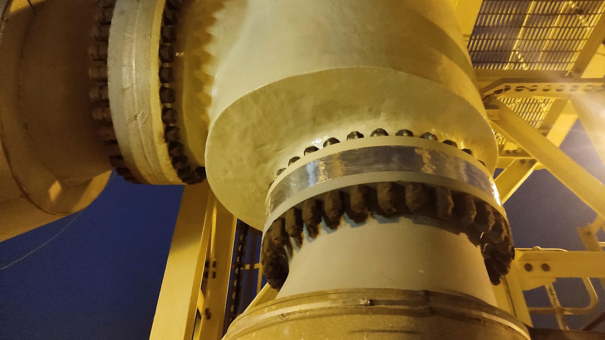
The primary objective of this job was to execute the structural verification service on the anti-surge valve. The task involved measuring the vibration values of the ASV to evaluate their severity by the Energy Institute's standards. Subsequently, we performed dynamic analysis and finite element analysis (FEM) of the valve support structure to design an effective vibration mitigation system.
Regulations applied
For the ASV classification (screening), we utilized the "Guidelines for the Avoidance of Vibration Induced Fatigue Failure in Process Pipework" from the UK Energy Institute.
The guidelines introduce the Concern Factor (CF) value to determine whether the amplitude and frequency of the measured vibration fall within acceptable, concerning, or problematic ranges, respectively, from 0 to 1, 1 to 5, and 5 and more. Values of 5 or more indicate vibration severity by evaluating the effective frequency (Crossing Frequency) and identifying potential fatigue failure risks.
| Variable | Formula | Remarks |
|---|---|---|
| Discrete Amplitude in Time domain | \(x_n\) for \(n=1,2,3...N\) | \(N\) is the total number of samples in the time block. \(x_n\) are the sampled values from the time waveform |
| Discrete Frequency | \(f_k\) for \(k=1,2,3...\frac{N}{2}\) | |
| Discrete Amplitude | \(X_k =FFT(x_n)\) for \(k=1,2,3...\frac{N}{2}\) | \(X_k\) are the complex FFT coefficients. The coeffients are scaled to RMS. |
| Overall RMS | \(X_{RMS} = \sqrt{\sum^{N/2}_{k=1} \vert X_k\vert^2}\) | RMS computation shown for enite spectrum \((k=1...N/2)\) |
| Crossing Frequency | \(f_c =\frac{ \sqrt{\sum^{N/2}_{k=1} f^2_k \vert X_k\vert^2}}{X_{RMS}}\) | Frequency at which the random signal crosses zero; represents the "effective" frequency of a broadband signal. |
Measurement and analysis
We equipped the ASV frame and valve with MEMS-type triaxial capacitive accelerometers and installed uniaxial IEPE accelerometers on the first and upper levels of the structure.
List of hardware and software
Hardware
AZIMA DLI DCX-09 - DCX vibration analyzer
IMI Sensors 603C01 - triaxial vibration sensor
MILC5015 Cable
Dewesoft SIRIUS-HD-16xACC - vibration collector
IMI Sensors 603C01 - uniaxial vibration sensor
Shielded BNC-BNC Cable
Dewesoft IOLITE-R8r - data acquisition system
Dewesoft 3xMEMS-ACC - MEMS vibration sensor
Ethernet Cable CAT 6
IRIS OM - slow motion amplification RDI camera
Laptop computer
Software
DCX Expert Alert ™ - for vibration analyzer
DewesoftX - for data acquisition, signal processing, and analysis
RDI - camera software
Our initial measurement results showed that we could separate the displacements and forces into two parts: the valve body and the actuator head, which produce more significant displacements and forces - see Table 2.
Maximum Displacement
| Axis | M1 - head | M2 - body | Unit |
|---|---|---|---|
| X | 1.86 | 1.18 | mm |
| Y | 2.35 | 5.01 | mm |
| Z | 0.61 | 1.91 | mm |
The vibration measurements showed significant displacements and forces in the valve body and actuator head. These measurements we used to evaluate the severity of the vibrations:
Maximum Displacements:
Actuator Head (M1): X: 1.86 mm, Y: 2.35 mm, Z: 0.61 mm
Valve Body (M2): X: 1.18 mm, Y: 5.01 mm, Z: 1.91 mm
|
Run-up and Coast-down Vibration Amplitueds - HV114020 |
||||||||||
|
Run-up A |
Frequency |
|
|
|
||||||
| Time | 5:29:50 |
5:32:30 |
5:12:40 |
|||||||
| Axis |
X |
Y |
Z |
X |
Y |
Z |
X |
Y |
Z |
|
| Amplitude (mm/s) RMS |
6.67 |
13.24 |
0.45 |
7.32 |
9.84 |
6.34 |
0.69 |
0.90 |
3.49 |
|
Run-up B |
Frequency |
2.32 Hz |
5.98 Hz |
7.81Hz |
||||||
| Time |
14:00.32 |
13:51:12 |
13:58:27 |
|||||||
| Axis |
X |
Y |
Z |
X |
Y |
Z |
X |
Y |
Z |
|
| Amplitude (mm/s) RMS |
1.82 |
2.96 |
0.09 |
7.68 |
8.38 |
5.70 |
2.19 |
0.98 |
7.01 |
|
|
Coast- down C |
Frequency |
2.32 Hz |
5.98 Hz |
7.81Hz |
||||||
|
Time |
18:53:09 |
18:36:29 |
19:16:09 |
|||||||
|
Axis |
X |
Y |
Z |
X |
Y |
Z |
X |
Y |
Z |
|
|
Amplitude (mm/s) RMS |
2.24 |
3.67 |
0.12 |
8.53 |
9.46 |
7.43 |
5.07 |
2.60 |
15.15 |
|
|
Vibration Assessment Criteria - HV114020 - Top - Load 850 Tn/h |
|||||||||||
| Axis |
Amplitude (mm/s) RMS |
Fe [Hz] |
A [mm/s RMS] |
Con- cern Factor |
% |
Criteria |
|||||
|
F [Hz] |
2.44 |
4.15 |
5.86 |
6.84 |
11.72 |
||||||
|
X |
0.897 |
4.3 |
10.3 |
6.46 |
10.9 |
8.82 |
16.91 |
3.61 |
65 |
Concern |
|
|
Y |
1.15 |
1.43 |
4.82 |
11.4 |
16.1 |
10.11 |
20.39 |
4.09 |
77 |
Concern |
|
|
Z |
1.32 |
0.738 |
0.765 |
2.53 |
3.11 |
9.38 |
4.35 |
0.90 |
90 |
Acceptable |
|
|
X |
1.01 |
2.14 |
6.56 |
7.24 |
13.1 |
10.06 |
16.51 |
3.52 |
58 |
Concern |
|
|
Y |
1.41 |
0.81 |
8.66 |
8.73 |
16.2 |
10.07 |
20.40 |
4.10 |
77 |
Concern |
|
|
Z |
0.09 |
0.285 |
4.84 |
4.09 |
1.82 |
6.85 |
6.60 |
1.59 |
15 |
Concern |
|
|
X |
1.22 |
2.03 |
6.62 |
6.34 |
4.29 |
7.45 |
10.39 |
2.41 |
35 |
Concern |
|
|
Y |
1.47 |
1.11 |
7.59 |
7.68 |
4.29 |
7.26 |
11.76 |
2.76 |
44 |
Concern |
|
|
Z |
0.119 |
0.445 |
0.705 |
4.25 |
0.517 |
6.88 |
4.36 |
1.05 |
1 |
Concern |
|
We designed a viscous damper (Visco-damper) to absorb and minimize these displacements based on our measurement results. This damper has a more substantial damping than the existing one, with a maximum damping of 40%.
Design options for vibration mitigation
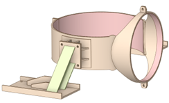
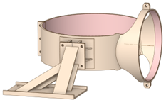
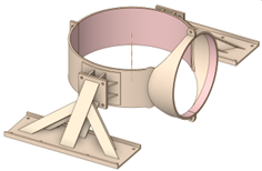
We proposed three support structures with different damping characteristics:
Option 1: One shock absorber per side with a damping resistance of 161 kN/m each and a maximum damping force of 14 kN each.
Option 2: Adding a spring system to support the static load or preload of up to 33.5 kN on each side.
Option 3: A combination of shock absorbers and springs optimized for damping and structural support.
Option 1: one shock absorber per side
Option 1 involves installing one shock absorber per side, each with a damping resistance of 161 kN/m and a maximum damping force of 14 kN.
Pros:
Simplicity: The design is straightforward, involving only two shock absorbers. This simplicity can facilitate installation and maintenance.
Cost-Effective: Fewer components generally mean lower initial outlay and ongoing maintenance costs.
Effective Damping: Provides significant damping resistance, effectively reducing vibrations.
Cons:
Limited Damping Range: It may only provide sufficient damping across some operating conditions, particularly if vibrations exceed the design parameters.
Potential for Overloading: Overloading may reduce the shock absorbers' effectiveness, leading to insufficient vibration mitigation.
Option 2: spring system
Option 2 includes adding a spring system to support the static load or preload of up to 33.5 kN on each side.
Pros:
Static Load Support: This provides excellent support for static loads, which can reduce the stress on the valve structure and extend its lifespan.
Dynamic Response: Springs can absorb and dissipate energy from dynamic loads, helping to mitigate vibrations effectively.
Cons:
Complexity: This option involves more components and a more complex design than Option 1, potentially leading to higher installation and maintenance costs.
Potential for Resonance: Improperly tuned springs can resonate at specific frequencies, which could amplify rather than dampen vibrations.
Option 3: combination of shock absorbers and springs
Option 3 combines shock absorbers and springs to optimize damping and structural support.
Pros:
Optimized Damping: Combines the benefits of shock absorbers and springs, providing robust damping across a broader range of operating conditions.
Versatility: Tailorable to address static and dynamic loads, ensuring comprehensive vibration mitigation.
Enhanced Structural Support: The spring system provides additional structural support, reducing the overall stress on the valve and its components.
Cons:
Higher Cost: More components and a complex design mean higher initial costs and potentially higher maintenance expenses.
Complex Installation: This installation is more complicated and requires precise calibration of shock absorbers and springs to ensure optimal performance.
Maintenance: More components mean more potential points of failure and increased maintenance requirements.
Option 1 offers a simple and cost-effective solution but may need improvement to handle all operating conditions. Option 2 provides excellent static load support and dynamic response but can be complex and potentially resonant at specific frequencies. Option 3 offers the most comprehensive solution, combining the strengths of shock absorbers and springs, but comes with higher costs and complexity in installation and maintenance.
The gas plant must choose the optimal solution after weighing these pros and cons against its specific operational requirements and constraints.
Structural analysis and design - new structure design
For the proposal to stiffen the structure, the objective is to obtain displacements of the base structure with a ratio of less than 1/5 concerning the displacement of the insulation system (ASVs valve)
Analyzing the proposed structure at the most unfavorable frequency, 2.3 Hz, the relationship between the displacement of the base structure and the damping system is 1 to 5.77, meeting the requirement of the supplier of the GERB dampers.
Then, we verified that the structural elements have sufficient capacity to resist the opting design forces and a favorable design for Option 1.
We evaluated the existing structure to support the valve vibration mitigation system; the dynamic analysis results indicate its flexibility and low rigidity.
Analyzing the most unfavorable frequency, 5.9 Hz, the relationship between the displacement of the base structure and the damping system is 1 to 2.24, not meeting the requirement of the supplier of GERB shock absorbers for the correct functioning of the damping system (ratio of 1 to 5).
We evaluated the existing structure supporting the valve vibration mitigation system, using two shock absorbers and an isolator on each valve side.
Analyzing the most unfavorable frequency, 5.9 Hz, the relationship between the displacement of the base structure and the damping system is 1 to 4.17, which does not meet the supplier of GERB shock absorbers' requirement for the correct functioning of the damping system (ratio of 1 to 5).
Assembly of structure and valve support
We used Finite Element Analysis (FEA) to validate the proposed designs. The analysis included:
Operation Deflection Shape (ODS) Analysis: Identified the frequencies and amplitudes of vibration, with significant movements observed at 2.3 Hz and 5.9 Hz frequencies.
Operational Modal Analysis (OMA): Confirmed the structural movements and vibration periods, which we validated through structural analysis using SAP2000 software.
Fatigue and impact analysis
We conducted a detailed fatigue analysis to evaluate the possibility of failure due to cyclic forces. The study involved calculating average and alternating stresses and determining the safety factor. We also performed an impact force analysis to assess the effects of sudden deceleration forces on the structure.
| MAXIMUM DEFORMATION | |||||||||
|
FREQUENCY |
Design 1 |
Design 2 |
Design 3 |
||||||
 |
 |
 |
|||||||
|
X (mm) |
Y (mm) |
Z (mm) |
X (mm) |
Y (mm) |
Z (mm) |
X (mm) |
Y (mm) |
Z (mm) |
|
|
2.3 Hz |
0.036 |
0.390 |
0.360 |
0.034 |
0.109 |
0.109 |
0.039 |
0.125 |
0.151 |
|
5.9 Hz |
0.091 |
0.653 |
0.492 |
0.043 |
0.175 |
0.136 |
0.043 |
0.154 |
0.187 |
|
7.9 Hz |
0.077 |
0.466 |
0.478 |
0.065 |
0.189 |
0.206 |
0.141 |
0.046 |
0.082 |
| MAXIMUM STRESSES MPa | |||
| FREQUENCY |
Design 1 | Design 2 | Design 3 |
 |
 |
 |
|
|
2.3 Hz |
142.79 | 80.949 | 138.03 |
|
5.9 Hz |
411.13 | 105.78 | 134.43 |
|
7.9 Hz |
209.22 | 129.50 | 71.17 |
Implementation and results
The selected vibration mitigation design involved viscous dampers and springs mounted on a newly designed structural support. The FEM analysis confirmed that the designed supports met the required stiffness and damping criteria, ensuring effective vibration mitigation for the ASVs valve.
The final installation involved the following components:
Viscous Damper: RRD-300/V40/H25 TU model with a maximum damping force of 14 kN.
Spring Support: VL24-457 spring for static load support.
This comprehensive approach to structural verification and vibration mitigation significantly reduced valve displacements and forces, ensuring the reliability and safety of the ASV in the gas company’s plant.
We recommended the modified structure design 2 with the valve support version 3. See the Figure 14.
Once the gas plant has installed the damping system, we recommend verifying the displacements, relaxation time, and resulting forces under maximum load conditions at plant stop and start.
When the gas plant has installed the damping system, we will use strain gauges to perform stress verification measurements on the actuator supports in conditions of maximum load, plant stop, and plant start.
The chosen solution combines shock absorbers and springs to mitigate vibrations in the anti-surge valve at the plant. The benefits of this option are:
Optimized Vibration Damping
Wide Range of Damping: The system effectively dampens vibrations across a broader range of frequencies and amplitudes using shock absorbers and springs. This damping ensures the anti-surge valve operates smoothly under various conditions, reducing the risk of vibration-induced damage.
Balanced Energy Dissipation: Shock absorbers handle high-frequency, low-amplitude vibrations, while springs address low-frequency, high-amplitude vibrations. This complementary action provides balanced energy dissipation.
Enhanced Structural Support
Static Load Management: The spring system supports static loads, reducing stress on the valve structure. This system prolongs the valve's lifespan by preventing fatigue and structural failures.
Preload Handling: Springs help manage preloads effectively, ensuring the valve remains stable and aligned during operation.
Improved Operational Stability
Reduced Wear and Tear: The combined system minimizes the mechanical wear and tear on the valve components by reducing excessive vibrations. This reduction leads to lower maintenance requirements and extended intervals between servicing.
Consistent Performance: With better vibration control, the valve's performance remains consistent, improving the overall reliability and efficiency of the gas plant operations.
Cost Efficiency in the Long Run
Lower Maintenance Costs: Although the initial installation might be more expensive, the reduction in maintenance costs over time due to less frequent repairs and component replacements offsets the initial investment.
Increased Equipment Lifespan: The enhanced protection provided by the combination of shock absorbers and springs extends the operational life of the anti-surge valve and associated equipment, leading to long-term cost savings.
Safety Improvements
Reduced Risk of Failure: Effective vibration mitigation minimizes the likelihood of valve failure, enhancing the safety of the gas plant where equipment failure can have severe consequences.
Stable Operations: Ensuring the valve operates within safe vibration limits minimizes the risk of operational disruptions and contributes to a safer working environment.
Customizable Solution
Tailored to Specific Needs: The combined system can be customized to meet the gas plant's specific operational requirements and environmental conditions. This solution’s flexibility ensures precise tuning for optimal performance.
Scalability: The approach can be scaled or adjusted as needed, accommodating changes in operational demands or equipment upgrades without significant redesigns.
Conclusion
Once we installed the damping system, we verified the displacements, relaxation time, and resulting forces under maximum load conditions at plant stop and start. We also performed stress verification measurements on the actuator supports with strain gauges on the installed damping system in conditions of maximum load, plant stop, and plant start.
The combination of a redesigned structure and valve support, shock absorbers, and springs provides a comprehensive solution for vibration mitigation in the anti-surge valve at the gas plant. This solution offers optimized damping, enhanced structural support, improved operational stability, long-term cost efficiency, safety improvements, and a customizable approach. It is the most suitable choice to address the plant's needs and ensure reliable and efficient operations.
This case demonstrates the importance of a detailed structural verification process in mitigating vibrations in critical industrial components. By combining advanced measurement techniques, dynamic analysis, and robust design methodologies, we implemented solutions that effectively enhanced the operational stability of the anti-surge valve at the gas plant.