


Dewesoft and Delta Motion: SCADA with EtherCAT & Modbus

July 10, 2025
Dewesoft Data Acquisition (DAQ) and real-time control systems enable engineers to integrate high-speed data acquisition with third-party controller systems, creating real-time Supervisory Control and Data Acquisition (SCADA) solutions. Delta Motion manufactures motion control systems across numerous applications and industries. Both companies support the EtherCAT interface for real-time control and automation. Here is how Dewesoft devices are utilized with Delta Motion’s RMC series motion controllers to address measurement challenges across various industries and applications.
This article covers a system example featuring Delta Motion’s RMC200 motion controller. However, the same type of SCADA configuration is possible using any PLC or controller system that utilizes DewesoftX-supported industrial communications and EtherCAT protocols.

The Modbus protocol
Modbus is an industrial protocol developed by Modicon to offer digital communication options for instruments and Programmable Logic Controllers (PLCs). Originally a serial bus protocol, Modbus was expanded to include network-based communications. Software plugins allow DewesoftX software to interface directly with Modbus TCP clients and servers. The client plug-in interacts with Modbus TCP servers, reading available device data and returning interactive commands. The server plug-in broadcasts most DewesoftX channels to external Modbus TCP clients. Delta Motion’s RMC series controllers serve data via Modbus TCP registers.


The EtherCAT protocol
EtherCAT® is an industrial protocol developed by Beckhoff to provide a simple connection and data transfer solution between devices and controllers for industrial equipment ecosystems. The protocol uses a bus topology to identify units and create the data transmission stream.
Read a top-level article about the EtherCAT protocol:
For even more EtherCAT information, read here.
Several Dewesoft data acquisition systems use EtherCAT to transmit data to the host PC and DewesoftX. The systems can also be connected to compatible third-party EtherCAT masters, feeding the data into PLCs or controllers.
Dewesoft’s IOLITE, OBSIDIAN, and SIRIUS systems provide optimum flexibility via their dual-mode system. DewesoftX software acquires the data for logging and analysis while the controller reacts and controls the test system. IOLITE Rack (R8, R8R, and R12) and OBSIDIAN systems have dual EtherCAT buses: the primary bus streams data to DewesoftX while the secondary bus streams to a third-party EtherCAT master. With SIRIUS, the EtherCAT bus connects to the third-party master, and high-speed USB provides data to the DewesoftX software.
With Delta Motion’s RMC200 and ECAT module, Dewesoft hardware can send data directly to the RMC200 for use in their control logic programs.


Building a motion control SCADA system with Dewesoft and Delta Motion
With Delta Motion RMC200 controllers, Dewesoft’s dual-mode capabilities and Modbus TCP combine to create a complete system solution. Dewesoft signal conditioning and analog-to-digital (ADC) hardware provide high-quality data from the sensors to the controller and the host PC running DewesoftX software. DewesoftX communicates with the RMC200 to pull information and provide commands while logging the data. DewesoftX also provides a graphical, easy-to-use interface for the operators. The RMC200 uses data and commands from DewesoftX as inputs to provide high-speed, low-latency controls for the motion equipment.
Configuring the Dewesoft hardware
Referring to the illustration below, we connect the dual-mode IOLITE R8's primary bus (a 7-pin LEMO connector) to the PC using a LEMO to RJ45 adapter.


Next, DewesoftX is launched, and the input channels are configured in the standard way. When this is done, we store the configuration locally on the IOLITE. This is done by using the “Set power on default” function, which can be accessed by right-clicking the “Ampl. name” column and selecting it in that menu, or by clicking the button in the Channel actions next to the Dynamic acquisition rate. If the button is not visible, use the […] button and enable that option.


The data values will flash briefly without data and then resume operation once the channel information is set. The IOLITE acquisition hardware is now ready to connect via its secondary bus to the RMC200 motion controller.
Configuring the Modbus TCP client
Now let’s add the Modbus TCP Client plug-in, which connects DewesoftX to the RMC200, to request needed program data and issue commands. Under DewesoftX project settings, go to “Extensions” and add the Modbus C plug-in.


Click on the Modbus C plugin, then load the device configuration settings to instantiate Modbus TCP communications. Add a new device and set the device information to connect to the RMC200. When connected and configured correctly, you will see a green “Connected” message in the dialog box, and the IP address will have a green background in the plug-in settings. Click [OK] to return to the channel setup. You will then have access to the Modbus C module in the system setup.


Now you can set up the holding registers you want to read and write in the Modbus C module. Add the registers using the Add button under the Holding Registers tab and fill out the register information for each one. RMC units use 32-bit registers for allocating data, so you should select either “Int 32 signed” or “Float 32” depending on the register settings seen in RMCTools under “Address Maps” and “Variable Table”. You will see the data in those registers once the RMC200 is connected to the PC.


Adding the RMC200 to the system
Now that the Dewesoft hardware and software are configured to communicate with the RMC200 motion controller, let’s configure it.
Please add your ESI files to the EtherCAT ESI Manager under “Tools” in the RMCTools program. The EtherCAT ESI descriptions for various Dewesoft devices can be downloaded from the page below:
Dewesoft downloads, other software:
Other software

 and ESI Manager Dialog Box (3)")
Next, connect IOLITE’s secondary bus to the RMC200. Using a standard CAT5 (or higher) cable, connect the IN side of the secondary bus (RJ45 sockets) to the RMC200 ECAT module in the main port. Under the “EtherCAT” window from the project view, use the “Configure Using Network Scan” feature to automatically detect the IOLITE R8 and all installed IOLITE cards. This can also be entered manually using the “Add SubDevice After” option if you right-click any device in the EtherCAT menu.
Please note that device order is critical for the correct operation of EtherCAT systems!

, and manually adding sub-devices (right)")
At this point, we can write our user programs and triggers, set up the Modbus registers for holding reference data and command locations, and finally connect a CAT5 or better cable from the ETH1 port to the PC or a network switch connected to the PC for handling Modbus TCP communications. Please note that EtherCAT cables should always be directly connected to the PC, as EtherCAT does not use standard TCP/IP addressing and cannot be recognized properly when connected to a network switch. This requires two network interface ports on the PC running the system.


Building the user interface
With all hardware configured and connected, we can turn to the final major design step, the user interface. DewesoftX offers excellent tools for designing screen layouts and data displays, utilizing its extensive assortment of built-in widgets. From graphs, gauges, and buttons up to specialty widgets for GPS and aeronautics, the only limitation is the user’s imagination. We also support multiple simultaneous displays using any number of connected monitors for more complex tests and operating systems.
To do this, navigate to the “Measure” tab in Measure Mode. Here we can set up our displays to show critical data for monitoring during operation, create any display navigation needed for handling multiple displays, create input controls for any Dewesoft actions we want to access easily (start/stop acquisition, store/arm, pause, freeze, etc.), and assign controls, meters, and graphs to Modbus register channels to interact with the RMC200.
Below is a sample interface from a simple SCADA demo using an IOLITE R8 and RMC200 Lite with the following configurations:
The RMC200 is programmed to monitor for an over-temperature condition from a K-type thermocouple connected to the IOLITE R8 and send a digital out to simulate an output to the stand.
Communicating a voltage setpoint target to an external adjustable power supply using Modbus TCP. DewesoftX sends the setpoint command to the RMC200 via Modbus TCP, and the RMC200 responds by generating an analog output to the external power supply.

Two analog meters show the current temperature of two thermocouples. The red line is based on a manual maximum of 85°F to visualize the overtemperature zone.
Digital meters with 100% transparency and caption/border lines are disabled to display the same temperature as the corresponding analog meter. This is good for showing the exact value attributed to each analog meter.
An indicator lamp for overtemperature is assigned to the digital input channel and wired to the RMC200 output channel. When the RMC200 program detects the overtemperature condition and sends the HIGH output, this lamp turns red.
An Input Control is set to “Up Down Button” and assigned to the Run Program Modbus register. Turning this input ON sends a command to the RMC200 to start the associated user program. The RMC200 program will monitor this command at the end of each control loop and initiate a safe shutdown process when this input is turned off.
An Input Control is set to “Up Down Button” and assigned to the ESTOP Modbus register. Enabling this input will send a command to stop the program at the end of the current step.
A horizontal bar widget is set to a 3D bar and assigned to a scaled analog input tied to the RMC200 analog output. When the Modbus command from DewesoftX is updated, this widget shows when the RMC200 has sent the analog output.
A digital meter is assigned to the same channel as #6 to provide the exact value on the bar.
An input control is set to the input field and assigned to the Target Voltage Modbus register. When the user enters a value, the RMC200 sees the updated Modbus register and sends the corresponding analog output to get that value from the power supply.
Conclusion and more information
Dewesoft EtherCAT-based DAQ instruments are ideal additions to any industrial SCADA system. They provide high-speed data acquisition, typically missing from these systems, with a graphical and highly flexible user interface. Their ease of integration saves time and money while maximizing results. You will find instruments from Dewesoft and Delta Motion in various applications, from general manufacturing to automotive, metalworks, plastic processing, energy production, and many more.
Below this article, you will find more detailed information about setting up several Delta Motion models. Reference #1 shows setup instructions for the Delta Motion RMC75 and RMC200, and Reference #2 shows EtherCAT SCADA setup with the RMC200. We hope this detailed information is helpful to engineers worldwide.
Learn more about Dewesoft DAQ instruments: systems")
Learn more about Delta Motion motion controllers.
EtherCAT® is a registered trademark, licensed by Beckhoff Automation GmbH, Germany.
All trademarks are recognized as the property of their owners.
Reference 1: Delta Motion RMC75E and RMC200 setup instructions
Unit setup
Required hardware:
Delta Motion Controller
24VDC Power Supply, at least 500mA
Wire
Ethernet Cable

 setup")

 setup")
Delta Motion datasheets and manuals:
Initial project creation and unit connection using RMCTools software
Refer to Delta Motion’s Startup Guide for detailed instructions on how to start a project and connect to your RMC unit
Note: If connecting to the unit through Ethernet and the setup wizard cannot find the unit, see Appendix A-1 for troubleshooting
Finding Modbus/TCP registers in RMCTools
With a project open and a controller assigned, we can view the Modbus addresses for all registers in the controller. In the project view, double-click “Address Maps,” which will open a new tab with all address map options. Select “Modbus” next to view those register addresses.


Communication using DewesoftX and Modbus C plugin
Now that we have the Modbus register addresses, we can set up DewesoftX to communicate with the device.
In DewesoftX, start a new setup.
First, we must set up the connection to the RMC through Modbus. Go to options and select settings. Click the “Extension” option on the sidebar. Find “Modbus C” under the Plugins group and select it. The plugin setup will show next to the extension selection scroll box.
Note: If “Modbus C” is not listed, click the (+) at the top. The “Manage Extensions” dialog box will open. In the search bar, type “Modbus”. Click the circle next to “Modbus C” and click “OK” to add it to your extensions.


In the Modbus plugin screen, click on the default device and click “Edit”.
We can edit the name and device settings in the new dialog box. Enter a name for the RMC controller, and update the host or IP address box with the IP address of the unit. Port will remain 502 (based on the Delta manual). Unit Identifier is not critical when using Modbus TCP, so please leave it at 255. Select “Word Swapped” to read/write data correctly. Delta puts the least significant 16 bits first in the registers. If you entered everything correctly, the status should change to green “connected”. Click on “OK” to save the changes.
The information should have been updated on the Modbus C plugin screen.
The “TCP Host: Port” will be highlighted green to show it is connected. Click “OK” to return to the DewesoftX main screen.
On the “Ch. Setup” tab, we will have a new icon on the ribbon for the Modbus C plugin. Click on it to bring up its setup screen.


On this main screen, uncheck “Minimize # of requests.” This will remove issues when trying to send commands and values over Modbus. Leave the “Address Display Offset” set to 1. Delta uses base index one (1) on its Modbus registers.
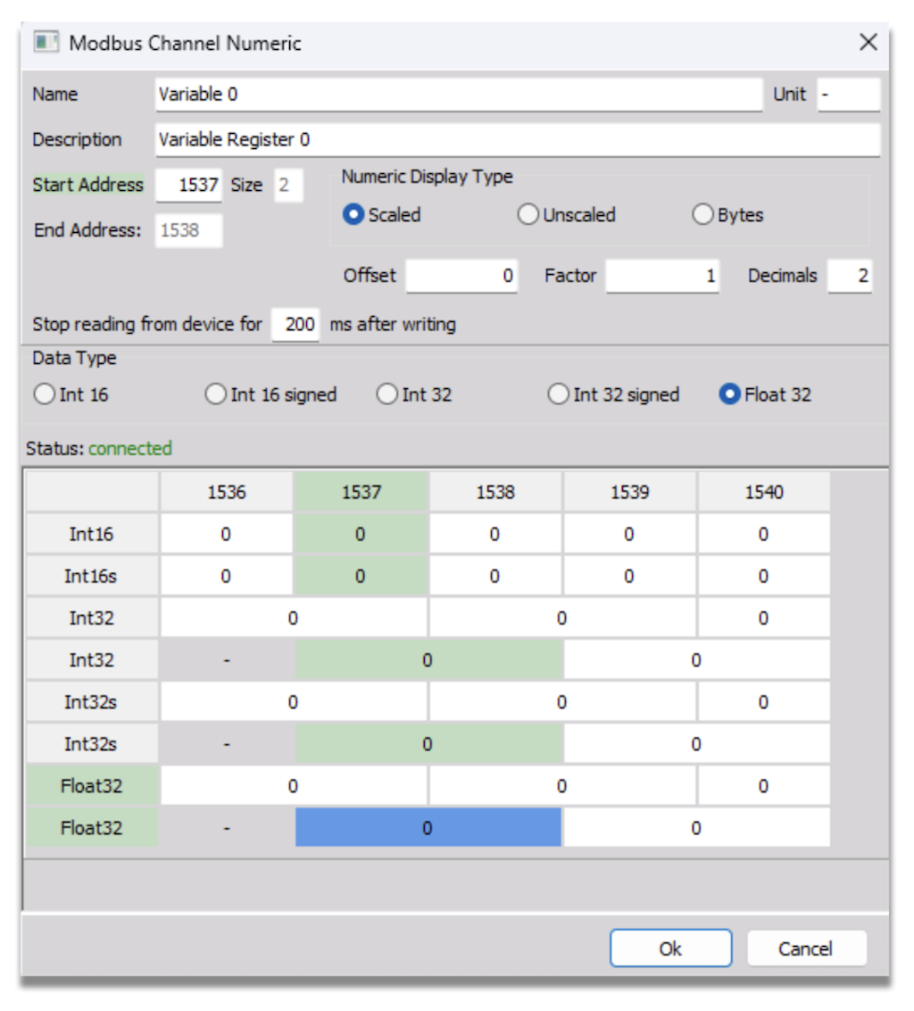
To add registers, click the “Holding Registers” selector and click “Add”. This will bring up a dialog box to set up the register information.
In the dialog box, you can enter the information to describe the register, Modbus address location, and the data type. For the RMC75, the main variable locations start at 1537, each size 2. The default RMC register data type is REAL, so we will select Float 32 to match. Be sure to set “Decimals” to at least one (1) so it can accept the Float 32 properly (it has accepted up to 7 decimal positions successfully). Click “Ok” to save the change or the (+) to add another register.
Note: If you need to make any changes to the registers, click on the register line you want to edit, then double click or click the “Edit” button to reopen the dialog box.
Note: The address map contains many other Modbus registers. For more information, refer to the RMCTools address map.

You are now set up and able to use the RMC Modbus channels on the “Measure” tab as a selectable Input/Output. They will appear in the “Channels” tab under “Modbus C/Modbus C/[Device Name]”


Appendix
A-1: troubleshooting first time Ethernet connection on RMC75E using RMCTools
Ensure the PC's connected Ethernet port is set to a static IP address. If it is, continue below.
While in the New Controller Wizard's Ethernet device search dialog box, click the “Troubleshoot…” button.


In the new dialog box, review the multiple IP interfaces section. If you have numerous interfaces with the same metric, it may not be checking the correct IP port. The case shown below checks the first Ethernet connection for a device, marked with an asterisk (*). We need it to check the second connection. The metric for that connection must be set lower than the rest to properly search for our device.


To change the IP Metric, go to the network connections on Windows (search for “View Network Connections”). Right-click on the Ethernet connection to modify and select “Properties.”


In Properties, find “Internet Protocol Version 4 (TCP/IPv4)”. Select it and then click the “Properties” button. In the new dialog box, click the “Advanced…” button. On the “IP Settings” tab, find the “Automatic metric” section. Uncheck the box and enter a value lower than all the other connections shown in the RMC troubleshooter earlier. Then, click “OK” on each of the dialog boxes to save the change.


Go back to the RMC Troubleshooter. It should have updated to show the newly entered metric value for the connected port. If so, close the troubleshooter to return to the setup wizard.


Reference 2: EtherCAT SCADA setup with Dewesoft hardware and RMC200
Additional documentation
Dewesoft Third-Party EtherCAT Master Manual
Hardware setup
Dewesoft Applicable Hardware
KRYPTON Series
IOLITE Series
OBSIDIAN
SIRIUS Units
Delta Motion Applicable Hardware
RMC200 Lite with EtherCAT module
RMC200 with EtherCAT module


Configuring the Dewesoft hardware:
The Dewesoft Third-Party EtherCAT Master manual provides detailed instructions for setting up the Dewesoft hardware with DewesoftX and connecting to the Third-Party Master. The manual also covers each supported unit and amplifier's operation modes and EtherCAT settings.
Configuring the RMC200:
Download the ESI files for Dewesoft hardware from the website and unzip the folder to the local drive.
In the RMCTools software, open “Tools” in the menu bar and select “EtherCAT ESI Manager”.
Click the “Add Folder” button, navigate to the unzipped folder location, and click “Select Folder.” This will load all of the ESI files into RMCTools, which you can use to build the EtherCAT device chain.
In the Project View area, double-click “EtherCAT” to open the EtherCAT editor view.
There are two methods for setting up the EtherCAT chain. The first step is to connect the device chain to the RMC200 EtherCAT module and utilize the “Configure using Network Scan” feature. The second option is to add each device manually in the editor.
To perform the network scan, connect the EtherCAT device chain to the RMC200, then click the magnifying glass above the EtherCAT explorer area or right-click “EtherCAT MainDevice” and select “Configure Using Network Scan.”

")
Once the detected chain is loaded, confirm that the hardware was identified correctly. If using the IOLITE or OBSIDIAN secondary bus, you may need to manually change the device between the “bus 1” and “bus 2” versions. Right-click the device you wish to update and select “Change SubDevice”.
The Change SubDevice dialog box lists the applicable device descriptions that match the selected base device. Select the description you want to use and click “OK.” The device name will not change, but the description file information will update.

")
To manually add EtherCAT devices, right-click on the last device in the chain and select “Add SubDevice(s) After.” This will open a dialog box containing all available ESI descriptions in RMCTools. Select the device to add and click “OK” to add it to the chain. Repeat this process until the full chain is loaded.

")
Click the “Download EtherCAT Configuration to Controller” icon above the EtherCAT Explorer. This will send the configuration to the RMC200 and restart the EtherCAT communications. If there is an issue with the setup, the NET light on the RMC200 EtherCAT module will flash red. If that light is green, communications are established, and data is transmitted.
If there are any errors, you can open the EtherCAT Diagnostics to identify and troubleshoot issues, review the status of any device on the chain, or check the received data.
For information on using the EtherCAT data in the RMCTools program, please review the RMCTools help files provided in the software.