


Railway Seat Comfort Accelerometer Calibration Following ISO 8041-1
Ane Etxezarreta
Mondragon University Higher Polytechnic School, CETEST
October 1, 2024
Ensuring passenger comfort in railway vehicles involves rigorous testing to measure and evaluate seat and backrest vibrations. Such measurements are standardized and reliable by adhering to international standards like ISO 2631-1 and ISO 8041-1. Seat comfort accelerometers allow for precise assessment of the vehicle's movement and its impact on human comfort. Their calibration is essential for producing a comprehensive comfort index that reflects real-world passenger experiences. CETEST developed a new process for calibrating seat comfort accelerometers using Dewesoft data acquisition and analysis.
Officially established and recognized in 1997, Mondragon University (Basque: Mondragon Unibertsitatea (MU) is a non-profit cooperative and private university in the Basque Country. Mondragón Goi Eskola Politeknikoa (MGEP) is a research co-operative integrated in the Mondragón Corporation and Mondragón University. Its research model integrates research, training, development, and innovation activities.
MGEP’s research areas include advanced processes for transforming materials, mechanical behavior and product design, new and advanced materials, information and communication technologies, organization, and industrial management. MGEP students have the possibility of working part-time for enterprises. In my case, the choice was CETEST.
CETEST is a test and analysis center based in the Basque Country. The center provides global testing, engineering, and monitoring services. Cetest is a fully accredited independent test laboratory offering services for design verification, model validation, developmental testing, troubleshooting, and fault diagnosis:
CETEST emerged in 2007 as an independent company providing testing services and has since helped leading railway companies in regulatory approval processes for new and refurbished vehicles, components, and systems worldwide.
The issue - comfort testing
Comfort tests on railway vehicles are comprehensive evaluations conducted to ensure a pleasant and secure passenger experience during train journeys. They underline the importance of accurate and standardized seat and backrest vibration measurements.
The vehicle's behavior depends on speed, load, suspension, road condition, and layout, among other factors. All of them influence the comfort of passengers. Thus, we performed tests according to each assessment condition, following the methods defined in international standards.
For the performance of these tests, we used a combination of specialized measuring instruments, among others, seat comfort accelerometers, to evaluate the vehicle movement by measuring the magnitudes that affect the perception of human comfort. We processed these measurements to obtain the comfort index and assess human exposure to vehicle vibrations. In addition, these sensors need to be calibrated according to ISO 8041-1 to comply with the standard ISO 2631-1.
Relevant standards
Overview of the relevant standards for calibrating train seat comfort accelerometers:
ISO 8041-1 (Human response to vibration — Measuring instrumentation): This standard specifies the requirements for instruments designed to measure vibration by the ISO 2631 series and other related standards.
ISO 2631-1 (Mechanical vibration and shock — Evaluation of human exposure to whole-body vibration): This standard and subsequent parts define the criteria for evaluating human exposure to whole-body vibration, ensuring accelerometers measure relevant vibrations affecting passenger comfort and health.
EN 12299:2009 (Railway applications — Ride comfort for passengers — Measurement and evaluation): Provides detailed guidelines for measuring and evaluating passenger comfort in rail vehicles, ensuring accelerometers can accurately capture relevant data.
ISO 10326-1:2017 (Mechanical vibration — Laboratory method for evaluating vehicle seat vibration — Part 1: Basic requirements): Standardizes the evaluation methods for seat vibrations, ensuring consistent and reliable measurements.
ISO 16063-21:2003 (Methods for the calibration of vibration and shock transducers — Part 21: Vibration calibration by comparison to a reference transducer): Ensures precise calibration of accelerometers by comparison with a reference transducer, maintaining measurement accuracy.
Application
The comfort standard ISO 2631-1 requires special accelerometers to measure seat and backrest vibrations. These accelerometers must be able to measure three axles from 0 Hz to 160 Hz. The EN 12299 standard requires the global transfer function of these sensors to be flat (within the tolerance ±0.5 dB), between 0.4 Hz and 100 Hz. After several tests and comparisons, I selected the most suitable accelerometer for this application.


On the other hand, the test procedure to ensure passenger comfort follows ISO 2631-1, and the calibration procedure for the applied sensors is also regulated. We have calibrated accelerometers according to ISO 16063-21 so far, but this procedure does not conform with the requirements for accelerometers used in comfort tests.
Our main problem in this project is selecting an adequate sensor with a good frequency response in the required bandwidth, designing the necessary support for installation in the seat, and making simple connections. Thus, we can calibrate the seating comfort accelerometers according to the ISO 2631-1 and ISO 8041-1 standards at a lower cost than commercial services.
Our solution
Hardware and software used
Acceleration Reference Sensor (ARS)
Power Supply for ARS
Acceleration Sensor (DUT)
Vertical Shaker
Power Amplifier
Position Controller
Vibration Control System
Calibration SW
SIRIUSe-HD-16xSTGS
DewesoftX
Sensor installation
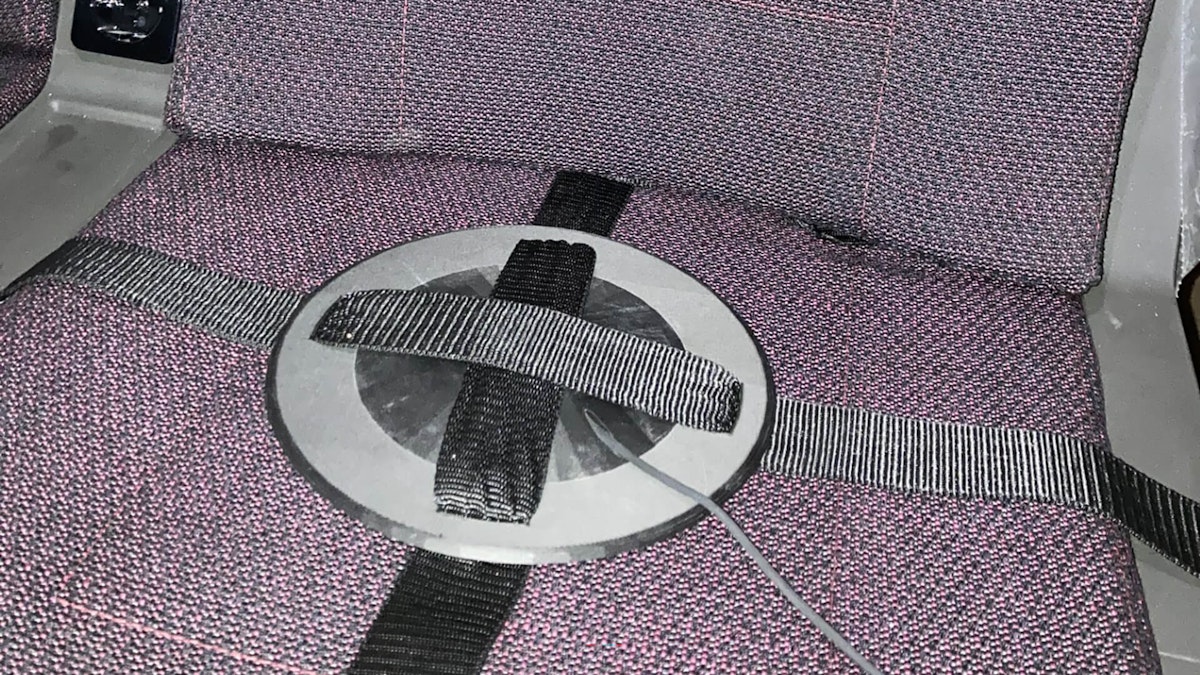
For laboratory vibration tests on vehicle seats, we must assemble the accelerometers according to the ISO 10326-1 standard and fix the sensor to calibrate at the center of a mounting disc. We designed this support according to the dimensions indicated in the standard and 3D-printed it according to the standard's requirements to place the sensor inside.


Once the accelerometer is mounted correctly on its support, these supports are placed in the seat backrest, as shown in blue in Figure 4. The accelerometer measures the acceleration in the three axes in the tests.


Sensor signal measurement
Since these are triaxial sensors and the analysis will be performed for each sensor axis, it is necessary to divide the signal into three different outputs. We designed a box to achieve this and made the connections - see Figure 5.


Calibration procedure
We carried out this calibration using the “side-by-side” method, which compares the sensor in calibration with a previously calibrated Acceleration Reference Sensor (ARS) with known correction and uncertainty.
In addition to the reference accelerometer, we needed a calibration test bench to vibrate at specific amplitudes and frequencies and a thermo-hygrometer to record environmental conditions.
The measurement chain consists of two parts. First, the calibration test bench must be connected and assembled, and then the accelerometer data must be calibrated using DewesoftX software.
On the calibration test bench, we attached the sensor to calibrate on the moving part’s top surface, extracted from its support, and placed the reference sensor on the bottom, which we joined using two screws - see Figure 6.

As we needed to calibrate each sensor in three axes, we attached the sensors in three directions for each calibration—see Figure 7.


We used the Dewesoft SIRIUS equipment to condition the sensor to calibrate, which we attached to the calibration test bench, and to read the sensor signal. However, to calibrate each sensor, it is necessary to use the same equipment and channel that will be connected later to the sensor during the tests.
SIRIUS modular is a versatile data acquisition system that provides high-end signal conditioning amplifiers for almost any signal and sensor, offering a high dynamic range (160 dB). First, the SIRIUS equipment must be powered and connected to the computer by USB, see Figure 8.


Next, we connect the output signal of each sensor axis to the corresponding channel.

Once we have made the connections, we must configure the channels using the DewesoftX software's Human Body Vibration (HBV) module. The weighting factors must be applied depending on where the comfort tests are applied. Figure 10 shows the frequency weights applicable for seated passengers in each axle according to ISO 8041-1.

 configuration panel in DewesoftX.")
The environmental requirements for the performance of the test are determined by paragraph 13.2 of ISO 8041-1.
Measurements
We divide the calibration into three different parts. First, we calculate the new sensitivity, then do the amplitude linearity analysis, and finally, we measure the sensor's response to frequency.
Calculation of new sensitivity
The first step in the calibration will be to adjust the sensitivity. To do this, we will excite the bench at the reference frequency and acceleration and compare it with the theoretical response that the sensor should have under reference conditions.
The new sensitivity value is calculated by measuring the response relative to the sensitivity value recorded in the previous calibration and knowing the expected concrete response in reference values.
Amplitude linearity in reference frequency
Next, we must keep the frequency in the reference value at 15.85 Hz to determine the amplitude linearity. The acceleration value changes successively, and we record the sensor response for each point. See the excitation to which we subject the sensor in Figure 11.


Frequency response
Last, to determine the response in frequency, we must keep the acceleration in the reference values and change the frequency, continuing the sequence shown in Figure 12.


Results
Once we complete all measurements, we record the weighted results of the sensor’s amplitude and frequency response - see the graphs in Figures 13 and 14.


Finally, we calculate the sensor's sensitivity, error, and uncertainty with the measured values and different errors for the amplitude and frequency linearity response.
Conclusions
The commercial sensors could have responded better in low frequencies with the compliance limits. However, those available to us were expensive. For this reason, we analyzed the option of searching for a triaxial miniature accelerometer to design the necessary supports and define an internal calibration procedure since a calibration test bench of accelerometers was already available.
For this purpose, we created a new support to position the sensor in compliance with ISO 10326-1 and a new connection box to condition the three channels.
We have defined and developed a new calibration procedure that responds to ISO 2631-1 regarding sensitivity calculation, amplitude linearity to reference frequency, and frequency response with associated uncertainty calculations.