


Monitoring Flow-Induced Vibration (FIV) in a Nuclear Pin Bundle
Simone Mozzon, Research & Applications Specialist and Marco Ramacciotti, Operations and R&D Manager, ISE
ENEA - National Agency for New Technologies, Energy, and Sustainable Economic Development
May 8, 2024
Flow-induced vibration (FIV) in fuel pin bundles is critical in nuclear reactor design and safety. Understanding these vibrations helps optimize reactor performance and ensure the integrity of nuclear fuel assemblies. ISE and the Italian National Energy Agency, ENEA, investigated the effect of FIVs on a prototype nuclear core. They induced vibrations through the flow of liquid lead at high temperatures. Dewesoft supplied hardware and software to acquire, digitize, and process vibration data from 24 strain gauges.
A nuclear pin bundle, also known as a fuel bundle, is a nuclear fuel rod collection arranged in a specific configuration within the core of a nuclear reactor. Each nuclear fuel rod typically consists of a long, slender tube made of a material, such as zirconium alloy, filled with nuclear fuel pellets. These pellets are usually composed of enriched uranium or plutonium compounds.
The nuclear pin bundle plays a crucial role in the operation of a nuclear reactor. During reactor operation, fission within the fuel pellets generates heat. This heat can produce steam, which drives turbines to generate electricity. The configuration and arrangement of the fuel bundles within the reactor core facilitate efficient heat transfer, maintain reactor stability, and control the nuclear reaction.
Flow-induced vibration (FIV) refers to the phenomenon where fluid flow past a structure induces vibrations in that structure. These vibrations can occur in various engineering systems, such as pipelines, heat exchangers, or nuclear reactor components.
FIV can arise due to several factors, including the unsteady nature of fluid flow, turbulence, fluid-structure interaction effects, and resonance phenomena. When the fluid flow frequency matches the structure’s natural frequency, resonance can occur, leading to potentially damaging vibrations.
The partners
ENEA is the National Agency for New Technologies, Energy, and Sustainable Economic Development. It is a public body that promotes research and technological innovation and provides advanced services to enterprises, public administration, and citizens in the energy and environment sectors and sustainable economic development.
Founded in 1997, ISE is an electronic engineering systems company specializing in consultancy services related to plant reliability and maintenance engineering, technical services in predictive maintenance and condition monitoring, and related training and coaching activities. The company mainly targets the industrial market, operating in many different sectors, including oil & gas, chemical, petrochemical, cement, energy, food & beverage, pharmaceutical, etc.
For the industrial market and original equipment manufacturers (OEMs), the company also offers research and development services relating to data acquisition systems, IIoT, Time series databases, ML algorithms, and complete applications based on specific needs. ISE also designs and markets Twise® products for Predictive Maintenance, Condition Monitoring, and Testing activities.
The experimental setup


Understanding and mitigating FIV may involve using appropriate design strategies, such as damping mechanisms, altering the structure’s geometry, or employing vibration isolation techniques. Engineers often use computational fluid dynamics (CFD) simulations and experimental testing to analyze and predict FIV behavior in engineering applications.
FIVs are a significant concern in the prototype and assembly of nuclear reactors that utilize fuel pin bundles. As coolant flows around the fuel pins within the reactor core, it can induce vibrations in the structural components. These vibrations can lead to various issues, including fatigue failure, wear, and potential damage to the reactor core. Understanding and mitigating FIVs are reactor design and operation aspects essential to ensure safety and efficiency.
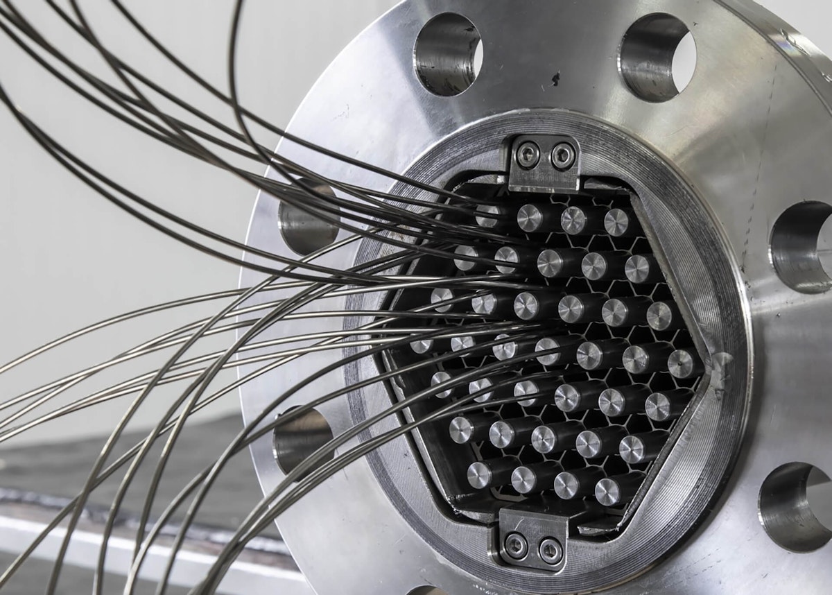
We designed an experiment to monitor FIVs on a prototype nuclear core, where the flow of liquid lead at a temperature of up to 550°C induces vibrations. The core part of the prototype consists of a test section, including a hexagonal bundle of 37 pins. Each pin is a 1.7m long hollow cylindrical tube full of perforated tungsten carbide pellets, which simulate nuclear propellant presence.
The test section, shown in Figure 3, further includes coupling flanges connecting the test section to the lead pumping system. A duck neck at the top of the test section allows the instrumentation cables to exit the lead-filled portion and connect to the data acquisition system (DAQ).


Monitoring system design
The measuring system was to monitor the amplitudes and frequencies of the pin displacement using a raw signal from strain gauges adequately installed into the test section. And to enable our evaluation of the uncertainty characterizing the measuring chain. We applied a system consisting of:
24x KYOWA KHC - temperature-resistant strain gauges.
3x Dewesoft SIRIUSie-8xSTGM 8-channel data acquisition systems.
KRYPTON CPU, a portable, rugged IP67 data logger and data processing computer.
DewesoftX data acquisition software for signal filtering, data processing, and visualization.
The experiment presents very challenging conditions: the monitoring system must sustain high temperature and pressure, a corrosive environment (flowing liquid lead), and the sensors must be installed within limited space. Transducers commonly used in vibration monitoring, such as accelerometers, are unfit for extreme environments, so we selected thin, temperature-resistant KYOWA KHC strain gauges. The strain gages were spot-welded on the pins - see Figure 4.
We installed the 24 strain gauges on four pins, two triplets of strain gauge for each pin, to capture the FIV modes, as shown in Figure 5. We selected each monitoring point to obtain optimal amplitude and direction measurements of the pin oscillations.
We identified Dewesoft 8-channel SIRIUSie-8xSTGM data acquisition as the best solution for acquiring and handling signals from the 24 strain gauge sensors. SIRIUS DAQ allows measurements at high resolution (24-bit delta-sigma) and signal-to-noise ratio (with a noise floor of 95 dB at 100 kHz bandwidth) while providing a modular system that allows stacking three devices while maintaining perfect data synchronization between channels.
The EtherCAT® interface simplifies the connection to the PC. We chose a fanless Intel NUC industrial PC with an I7 processor and 16 GB RAM. See our solution in Figure 6.


We used the bundled DewesoftX data acquisition software to filter each signal, process the data, and visualize it in a dedicated dashboard. We acquired the signals at a sample rate of 5 kHz, then reduced the noise by applying a low-pass filter at 30 Hz and averaging the result in windows of 0.01 s.
Finally, we elaborate on the resulting signals with two custom C++ scripts, which are included directly in the DewesoftX software.
A first script computes the bending direction and the radius of curvature of the pin at each monitoring point. A second script uses this information to calculate the total deflection of the pin in the transverse direction. Therefore, the resulting monitoring system is a real-time tracker of each pin transverse deflection. You may find further details on the data processing in T. Rovai et al. (2023).

.")


The experiment
To test the monitoring system, we realized a simplified test bench consisting of an aluminum tube instrumented with three SGs arranged in the triplet configuration as the SGs on the nuclear pins. We sealed the SGs at half the tube length to capture the tube's first vibration mode.
We acquired the SG signals using a Dewesoft KRYPTON® 3xSTG and extrapolated the pin transverse deflection amplitude using the same C++ scripts developed for the final setup. We then compared the output with a measurement from an analog linear displacement transducer. There was a strong agreement between the experimental results and the expected ones. See the test bench in Figure 7.


Figure 8 shows the DewesoftX dashboard recording a bump test performed on the test bench. The monitoring system captures the tube's oscillations. The software elaborates the raw signals from the SG triplet and converts them to a deflection in the x-y axis.


We then tested the monitoring systems on the fuel pins of the test section using a Dewesoft SIRIUSie-8xSTGM data acquisition system. Once again, we performed bump tests to verify the correct direction and bending amplitude reconstruction and found consistent results. Using DewesoftX, we developed a final dashboard that included the signals measured by each triplet of strain gages, the total deflection, and a graphical representation of the pin deflection in the x-y axis. Figure 9 shows a video recording of the dashboard during a bump test on a fuel pin.


We assembled the pin bundle consisting of 37 pins, with four pins instrumented with the strain gauges. See the final assembly in Figure 1.
We verified once again that the sensors could detect the movement bending the test section by gravity. We performed the latter test using the same PC that we later installed for the lead flow experiment. It's important to note that all these tests took place at room temperature.
Conclusion
The actual experiment with liquid lead is still undone. However, in this article, we present the realization of a nuclear core prototype consisting of a test section with a bundle of 37 pins. We instrumented four of these pins with six temperature-resistant strain gauges each to monitor flow-induced vibrations and measure the transverse deflection of the pins.
We adopted the Dewesoft SIRIUS DAQ device for data acquisition because of its customization, accuracy, resolution, and stability advantages. We extended the capabilities of the DewesoftX software framework with C++ scripts to calculate the pin deflection from the strain gages measured strains, visualizing the processed data on a custom DewesoftX dashboard.
We tested the system on a simplified test bench and the test section pins, confirming that it satisfies the experimental requirements. Finally, we verified that we can derive the vibration amplitude from measuring the pin deformation with a reasonable uncertainty of around 10%.
These measured and analyzed results were presented and published in the 2023 IEEE International Workshop on Metrology for Industry 4.0 & IoT.