


Integrating Dewesoft EtherCAT DAQ Systems with LabVIEW
Francesco Miccoli
May 28, 2025
EtherCAT® interconnects several DAQ (data acquisition systems) and control products within Dewesoft’s ecosystem, including the IOLITE, KRYPTON, and OBSIDIAN series. EtherCAT is a robust communication protocol that enables compatibility with various real-time systems, including Programmable Logic Controllers (PLCs). EtherCAT devices can be daisy-chained via a single cable that carries the data, power, and timing. DewesoftX software is included and works seamlessly with any combination of Dewesoft devices. However, there are times when National Instruments’ LabVIEW® has been deployed, and Dewesoft instruments must be integrated. This article shows how LabVIEW can connect and acquire data from Dewesoft EtherCAT devices. Although it applies to all Dewesoft EtherCAT-based systems, including IOLITE, KRYPTON, and OBSIDIAN, this article focuses on the IOLITEi 3xMEMS-ACC.
The IOLITE 3xMEMS-ACC is a Dewesoft data acquisition device with an embedded triaxial MEMS accelerometer, analog-to-digital converter, and EtherCAT interface. Multiple IOLITE devices can be easily distributed and synchronized over large structures using a single inexpensive CAT6 cable that can span up to 50 meters between nodes. Optical converters enable more than 20 km distances between devices while maintaining 1 µs synchronization accuracy. Precise time synchronization is crucial when performing OMA (Operational Modal Analysis) when evaluating structural dynamics, including natural frequencies, modal shapes, and damping ratios.
Like all Dewesoft measurement systems, IOLITE includes DewesoftX data acquisition software and signal conditioning. The product line comprises multifunction, high-speed data loggers for applications requiring automation control. They are available as single- and multiple-channel modules for low- and high-channel-count systems. They are standard EtherCAT slave devices sending data to any third-party EtherCAT master control system. When connected to DewesoftX DAQ software, retransmit functionality ensures no samples are lost during measurement.
Some IOLITE models are made to be mounted in standard 19” racks, while others can be mounted on a DIN rail. Tiny devices like the IOLITE 3xMEMS-ACC can be mounted directly next to the signal source, which reduces wire lengths from the sensor, thereby saving costs, simplifying complexity, and minimizing signal noise.


EtherCAT technology outline:

ENI file creation
EtherCAT devices can only be used within an appropriately configured EtherCAT network, which requires an ENI file. This file contains the complete configuration of the EtherCAT network, including a list of devices, communication parameters, synchronization details, and data exchange information.
The video above describes the Ackermann Automation EtherCAT Studio software and its usage. This tool allows us to add the IOLITE device from the library to the configuration tree. From there, we can create the ENI file (Master Configuration ETG Standard).


Data acquisition
The first step in acquiring data will be to set up our computer running LabVIEW software. This computer is the EtherCATmaster, which handles communication with IOLITE and other devices.
The Ackermann Library for LabVIEW offers convenient visual tools for this purpose. The images below show the “Open Master Windows Compact” block, which starts the local EtherCAT master. It takes in the previously created ENI file and network parameters, such as the bus cycle, target port, IP address, etc.


To acquire data, the master must be set in Operational (“Op”) mode. To do this, we can use the “Set Master State” block.

 mode.")
Now, we can code the acquisition loop: a “while cycle” that checks for new data at each iteration. Once data is available, it is unpacked and processed. The basic structure is:
Slave variables are queried, and the “Query All Slaves Variables” outputs a 1D array of clusters, each containing information about a slave variable such as data type, bit size, byte size, and more; this data will be used for numeric conversion during acquisition.
A while loop is used to perform continued data acquisition inside:
The “Read Process Data” block outputs the newly acquired frame.
A for loop sweeps across the number of slave variables and converts the frame to a more readable numeric value. The conversion is based on the “Base Data Type” property previously extracted during the slave variables query.
Finally, the acquired numeric data can be used. In the image below, the third element of the array is selected (this corresponds to the Z-axis acceleration, but it can be any other value) and concatenated before being plotted.


After the data is acquired, the program can be stopped via the control panel. This action activates the last portion of the code, where some cleanup is performed. This mainly consists of:
Setting the master state to Initialization (“Init”)
Closing the Ethercat master
Error handling
Device configuration
In the previous section, we explored data acquisition using LabVIEW, but how can we set our device's sampling rate and range?
First, we need to understand where device parameters are stored and how we can change them, according to Beckoff, the inventors of the EtherCAT protocol:
“The CoE interface (CAN application protocol over EtherCAT) is used for parameter management of EtherCAT devices.”
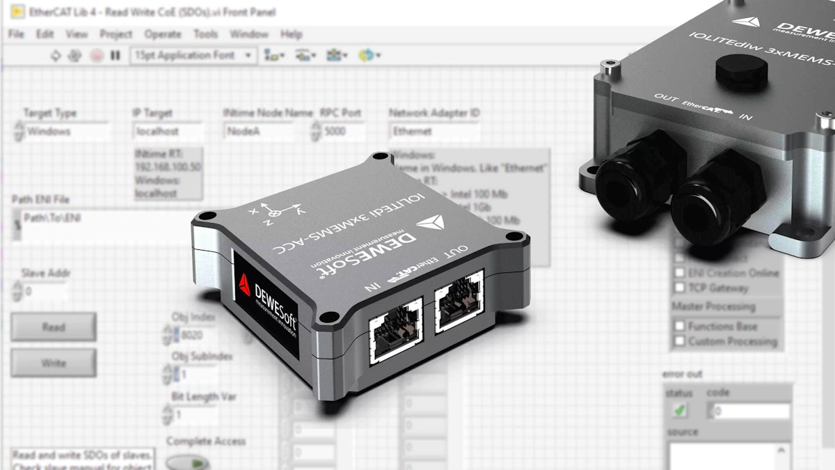
The same holds for the IOLITEi 3xMEMS-ACC. The Ethercat library previously installed provides an example named “Read Write CoE (SDOs),” which enables us to edit the device configuration.


The image above shows the control panel interface of this example. The most notable panels include:
Target Type refers to the master configuration wanted, with “Windows” selected.
To open the Windows EtherCAT master, you need the IP target, RPC port, network adapter ID, path ENI file, and timeout parameters.
Activation Data displays information on the active license.
Slave Addr refers to the address of the target slave inside the EtherCAT network. This number should match the position of the target slave within the configuration tree, with numbering starting at 0. Otherwise, the “Query Bus Setup” block can be used to better understand the overall network structure.
Obj Index and Obj Subindex refer to the target address, where each pair of index and subindex points to a different setting.
Data Write and Data Read are used to read/write data from/to the specified address. Typically, only one setting is changed at a time, so only the first element of the array is needed.
The following table links the indices to their respective functions:
| Property | Index | Subindex | Values |
|---|---|---|---|
| Sample Rate | 8020 | 1 | 3, 6, 12, 25, 50, 100, 125, 200, 250, 500, 1000 |
| X-axis range | 8040 | 1 | 0 (2g), 1 (4g), 2 (8g) |
| Y-axis range | 8041 | 1 | 0 (2g), 1 (4g), 2 (8g) |
| Z-axis range | 8042 | 1 | 0 (2g), 1 (4g), 2 (8g) |
| Power On Default | 8020 | 2 | 2 |
Conclusion
Integrating Dewesoft DAQ systems with LabVIEW via EtherCAT offers a robust and flexible real-time data acquisition and control solution. By following the outlined process—creating an ENI file, configuring the EtherCAT master, and utilizing LabVIEW’s Ackermann Library—users can seamlessly connect and acquire data from Dewesoft devices, including the IOLITEi 3xMEMS-ACC. The ability to precisely synchronize multiple devices across large distances makes this integration particularly valuable for structural dynamics analysis and automation applications. Additionally, leveraging the CoE interface allows users to fine-tune device parameters, ensuring optimal performance. This integration enables engineers and researchers to fully leverage the capabilities of Dewesoft DAQ hardware and LabVIEW in their measurement and control workflows.
For more information
A more in-depth technical user manual and an example LabVIEW VI are available. The manual will reflect future developments, including adding more devices to the test topology.
LabVIEW® is a trademark of National Instruments.
EtherCAT® and the EtherCAT® logo are trademarks or registered trademarks, licensed by Beckhoff Automation GmbH, Germany.
The Dewesoft logo is a registered trademark of Dewesoft d.o.o.
All trademarks are the property of their respective owners.