


Correlating Friction Noise and Mode Coupling Instability in High-Performance Braking Materials
Daniele Limiti (student)
University of Rome La Sapienza
October 17, 2023
The industry manufacturing brake pads and systems attributes significant importance to unstable friction-induced vibrations. These phenomena degrade surfaces, affect braking performance, and generate noise like brake squeals. With Dewesoft technology, I investigated the correlation between contact instabilities or mode coupling and the dynamic excitation deriving from frictional contact.
Friction-induced vibrations (FIV)
Frictional contact is a distribution of micro-impacts and local ruptures leading to the release of local elastic energy in acoustic waves - see Figure 1. The local phenomena result in a distribution of local dynamic excitation.

![Figure 1. Local phenomena are happening in a contact interface [1].](https://www.datocms-assets.com/53444/1697201299-local-phenomena-are-happening-in-a-contact-interface.png?auto=format&dpr=2&fit=max&w=1024 "Figure 1. Local phenomena are happening in a contact interface [1].")
A dry sliding contact is always the source of vibrations (FIV), releasing elastic energy in wave form, propagating both in the environment and the system itself. The latter has its inherent dynamical response to these excitations, leading to many kinds of behaviors:
Stable FIV: The system responds with its natural frequencies, but the dynamic response is steady with damping - material damping and joints - gradually dissipating the acoustic energy.
Unstable FIV: In this case, the system responds with dynamic instability, which causes high amplitude vibrations. The major macroscopic instability types are:
Stick-slip instability: is characterized by alternative phases of macroscopic sliding and sticking states, followed by impulsive system excitation.
Modal instability: feeds energy into an unstable system mode, leading to harmonic vibrations that increase exponentially in amplitude, up to a limit cycle dictated by contact non-linearities, causing significant noise emissions.
Mode coupling instability
My objective for this research is to investigate the correlation between the contact dynamic excitation, friction noise, and the occurrence of mode coupling instability.
Understanding the fugitive features of such unstable vibrations is needed to control and prevent their occurrence. They represent an issue for automotive breaking manufacturers widely recognized as the core phenomenon leading to brake squeal - see Figure 2.
This unstable vibration originates from the coalescence of two system modes at a definite friction coefficient value, the ratio between friction force and normal force. The real part of the eigenvalue becomes positive, meaning an apparent negative value of the respective modal damping. This phenomenon leads to auto-excited vibrations that grow exponentially in amplitude up to a limit cycle, irradiating noise.

 and real part (b) of the eigenvalues as a function of the friction coefficient, corresponding respectively to the oscillation frequency and growth rate.")


 showing the unstable frequency")
During the experimental campaigns I carried out to characterize the frictional and dynamic response of the tested samples, I used Dewesoft technologies. I obtained the tested materials from genuine brake systems, pads, and discs made of carbon-carbon composite material (C/C). The automotive industry increasingly adopts this high-performance material.
I needed high resolution and a broad range of measured vibrations, including a high harmonic response and low amplitude friction noise. For this reason, I chose to use a Sirius dual-core acquisition system, including DewesoftX data acquisition and signal processing software.
Experimental set-up
For the analysis, I employed a specific test bench, the TriboAir. The test bench allowed me to control the contact boundary conditions and avoid parasitic vibrations from other contacts in the experimental setup.
The TriboAir test bench - see Figure 3 - is in the laboratories of Tribology of the Department of Mechanical and Aerospace Engineering of the University of Rome La Sapienza.
The concept of the setup is to allow frictional sliding thanks to a system having moving components on air bushing. This way, no other contacts, except the one investigated, generate vibrations. The setup allows for precise and noise-free measurements of the frictional and dynamic system response.


I employed fundamental dynamics and geometry principles to analyze the impact of each parameter. I mounted samples of reduced dimensions on a loading support and a moving chassis. A linear voice coil actuator (BEI KIMCO LA30-75-001A) and a programmable controller drove the movable support with the motion rule assigned.
The air bearings allow the complete isolation of the examined contact from parasitic vibrations from the environment, which would otherwise pollute the measurements. For the same reasons, I chose a magnetic actuator to ensure the absence of elements in contact.
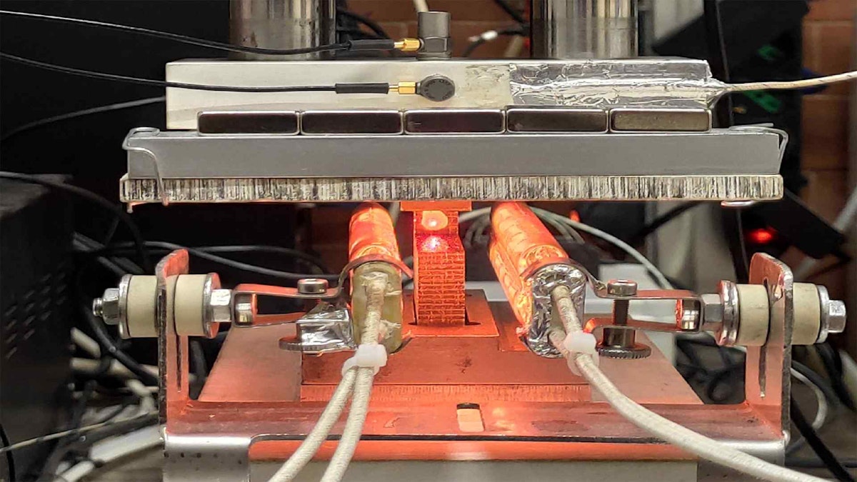
Two IR lamps bolted to the moving base controlled the temperature around the contact interface. I obtained the temperature control through a thermocouple placed inside the lower sample directly under the contact surface. A PID controller (GEFRAN F650) imposed the temperature rule.
Two three-axial force transducers (KISTLER 9017B) allow the measurement of the contact forces. They also enable the friction coefficient computation as the ratio between the signals from the tangential direction and the normal or perpendicular one.
Two IEPE (Integrated Electronics Piezo-Electric) accelerometers measured the vibrational response of the structure. A laser vibrometer (VibroFlex Neo VFX-I-110) had no direct structure interaction. It measured the upper sample vibrational signal, the closest possible, about 1 mm, from the effective contact surface.
By painting one face of the sample with a high-temperature-resistant paint, I obtained a reflecting surface suited for the test. To have an optimal signal reception, I also had to pay careful attention to aligning the laser - see Figure 4.


Signal acquisition system
An isolated SIRIUS data acquisition system based on DualCoreADC® technology recorded all data. It has a dual 24-bit delta-sigma (ΔΣ) analog to digital converters (ADC) for each channel - see Figure 7.


With DualCoreADC® technology, the SIRIUS data acquisition system can achieve more than 130dB signal-to-noise ratio and more than 160dB in dynamic range. That is 20 times less noise than the typical 24-bit systems - see Figure 8. This feature allows recording complex signals inclusive of high amplitude spectral components and lower amplitude contents, as in the case of this analysis.


Another significant characteristic of this acquisition system is the possibility of having different sampling frequencies for each input channel. It uses the lower ones for the slowest evolving signals, e.g., temperature from the thermocouples.
The electrical connections went through BNC connectors used for coaxial cables, designed to maintain the same cable impedance. These cables consist of an internal Cu conductor wrapped in a dielectric material, mostly PTFE, to separate it from the outer metallic shield that blocks interference.


An A/D conversion is the discretization, digitalization in particular, of a continuous signal (analog) through an operation of sampling. Sampling involves extrapolating a finite number of data samples from the input signal at regular time intervals ∆T, a sampling period. In this field, the Nyquist theorem represents a fundamental principle stating that the sampling frequency 𝑓s = 1/𝛥T must satisfy the condition:
with 𝑓MAX being the maximum frequency of the registered signal.
Not respecting the principle leads to a phenomenon known as ‘aliasing’ and loss of information.
Taking this into account, I defined the sampling rates for the acquisition channels as follows:
For the accelerometers and the laser velocity signals, I adopted a 100kHz sampling frequency since I use these signals to characterize the vibrational response.
The force transducers, as well as the displacement encoder signals, I sampled at 50kHz.
Finally, for the thermocouple and the laser level signals, I set a 125Hz sampling rate because of their slower time evolution.
Based on the signals, I performed ulterior mathematical operations in the DewesoftX software, as shown in Figure 11.


I defined the friction coefficient through the ratio between the input signal from the tangential force transducer and the normal load as seen in Figure 10. I made a necessary adjustment during the load parametric analysis to account for the actual applied load. I had to make this correction because the normal force transducer signals were affected by a drift phenomenon.
The drift meant that even when I maintained a constant load, the displayed value would shift due to thermal effects. To address this issue, I introduced a correction using an interpolating polynomial.


The alternating sign arises from the distinct directions of the strokes, both forward and backward. It's important to note that a negative friction coefficient doesn't hold any physical significance here. I solely employed it to distinguish between the forward and backward strokes. In the subsequent sections, I will only consider its absolute value.
I derived the velocity profile by taking the time derivative of the displacement signal recorded by the linear optical encoder - see Figure 13.


I applied a 6th-order Butterworth high-pass filter with a cutoff frequency of 5Hz to the accelerometer signals. I took this step to remove any low-frequency disturbances from the prescribed motion law. Furthermore, I computed a Short-Time Fourier Transform (STFT) on the filtered signals.

 Normal load, (2) Tangential force, (3) Samples temperature, (4) Velocity profile (magenta) and displacement (light blue), (5) Normal direction (Z) accelerometer signal, (6) Normal and tangential (X) accelerometers signals, (7) Laser velocity signal (green) and laser level, (8) Friction coefficient.")
Experimental campaign
I conducted multiple parametric experiments to explore the frictional and dynamic response concerning key contact parameters:
normal load,
sliding velocity, and
contact temperature.
The SIRIUS data acquisition system captured the signals and simultaneously recorded videos from two cameras throughout these tests. For instance, I recorded a video of the back and forward frictional contact using DewesoftX software. The video highlights a helpful software capability - real-time spectrogram visualization. This feature allowed me to observe the changing frequency patterns as they evolved during the recording.
Example of results
A notable observation arises when comparing two tests conducted at different velocities. Scholars commonly acknowledge that brake squeal is less likely to occur at higher velocity. You can make a contradicting observation when comparing a braking event on the highway to one near a traffic light. Yet, the existing literature doesn’t explain this phenomenon.


Figure 15 shows the difference between the friction noise measurements obtained at two sliding velocities at room temperature. The energy content in the higher velocity test is higher than in the lower velocity one because more power goes into the contact:
I could observe a principal difference in the frequency distribution of the vibrational energy. While it is true that the foremost frequency peak is higher at high velocities, relatively more energy is spreading along a broadband range.
At lower velocities, the energy focuses within a narrowband distribution. One plausible explanation for the varying likelihood of squealing at lower and higher velocities could be the broader frequency distribution of dynamic excitation originating from the contact. The wide distribution introduces disturbances at frequencies other than those associated with the unstable mode.
At lower velocities, the energy concentrates in a narrowband distribution. A possible explanation for the different squeal propensity at lower and higher velocities could be the wider frequency distribution of the dynamic excitation from the contact. The excitation distribution provides a disturbance to frequencies other than the one of the unstable mode.
On the other hand, at low velocities, the energy is concentrated around a narrow band. A significant perturbation of the mode frequency causes the system to become unstable. The result is the respective modal instability shown in Figures 14 and 15.

 showing the unstable frequency")

 from the laser velocity’s signal. At the bottom is the friction coefficient during the selected stroke, the accelerometer’s signal, the laser velocity’s signal, and the normalized spectrogram on the laser velocity signal.")
Conclusions
The brake manufacturing industry attributes significant importance to unstable friction-induced vibration. These phenomena generate noise like brake squeals and surface degradation.
The relevance of such phenomena has been increasing due to the introduction of new materials like C/C, which need an adequate tribological characterization. Over the past 80 years, numerous studies have addressed the elusive nature of automotive squeal noise and the challenges of understanding its causes. Despite extensive research, a definitive explanation still needs to be explored.
This study aimed to establish a connection between occurring contact instabilities, mode coupling, and the dynamic excitation from the frictional contact causing friction noise. To comprehensively characterize this frictional and vibrational phenomenon, I utilized Dewesoft technologies. These enabled precise signal acquisition from the TriboAir device across the entire frequency and amplitude range of interest.
References
Di Bartolomeo M., Massi F., L. Baillet, A. Culla, A. Fregolent e Y. Berthier: Wave and rupture propagation at frictional bi-material sliding interfaces: from local to global dynamics, from stick-slip to continuous sliding. Tribology International, vol. 52, pp. 117-131, 2012.
Hoffmann N., Bieser S., and Gaul L.: Harmonic Balance and Averaging Techniques for Stick-Slip Limit-Cycle Determination in Mode-Coupling Friction Self-Excited Systems. 2004.
Lacerra G., Di Bartolomeo M., S. Milana, L. Baillet, E. Chatelet e F. Massi: Validation of a new frictional law for simulating friction-induced vibrations of rough surfaces. Tribology International, vol. 121, pp. 468-480, 2018.
Lazzari, A., Tonazzi, D., Massi, F.: Squeal propensity characterization of brake lining materials through friction noise measurements. Mech. Syst. Signal Process. 128, 216–228 (2019).
Smith, G. Maloy: Dewesoft Data Acquisition Technology Explained. 2022.
Tonazzi D., Massi F., L. Baillet, A. Culla, M. Di Bartolomeo e Y. Berthier: Experimental and numerical analysis of frictional contact scenarios: from macro stick-slip to continuous sliding. MECCANICA, vol. 50, n. 3, pp. 649-664, 2015.