DC-CT® Current Transducers
The best AC⚡DC current sensor available today!
The Dewesoft power analyzer allows a comprehensive analysis of renewable generation units according to FGW-TR3, VDE-AR4105, and BDEW standards. Highly flexible hardware and innovative software save a lot of time during the testing process.
Enjoy our industry-leading 7-year warranty. Our data acquisition systems are made in Europe, utilizing only the highest build quality standards. We offer free and customer-focused technical support. Your investment into the Dewesoft solutions is protected for years ahead.
And we're confident you'll love it too! But don't just take our word for it. Get hands-on with a demo unit, completely free of charge. No strings attached, just real data. Reach out to your local Dewesoft team and get your demo unit now!
It includes everything you need for advanced data acquisition and common signal processing — no maintenance fees, no contracts. You buy it, you own it. All future updates? Free forever. And the best part? Analysis seats are unlimited and free. Once the data is recorded, anyone can download our software to review and analyze your data — no license needed.
Dewesoft is 100% owned by employees who believe in what we do — and love doing it. We’re in this with heart, passion, and long-term commitment. What does that mean for you? Our core value — caring for our customers — isn’t going anywhere. We’re here for the next 100 years, protected from outside acquisitions. Your investment in our technology is safe, supported, and future-proof.
At Dewesoft, quality isn't just a promise — it's a core value. Our products are 100% designed, developed, and manufactured in-house, right in the heart of the European Union. From precision machining and PCB manufacturing to final assembly and software development — we do it all ourselves, to the highest ISO standards. We're proud to support local production and take social responsibility seriously.
At Dewesoft, quality is more than just a word — it's a commitment. That's why our products come with an industry-leading 7-year warranty. It's just one more way we protect your investment and give you peace of mind for the long run.
Renewable power plants like wind, photovoltaic (PV), and CHP (Combined Heat and Power Plant) are more and more popular and the amount of already installed units is huge. For the operation of the public grid these renewable power generation units have to fulfill a couple of requirements to contribute to a stable operation of the grid.
The standards, which define the conditions for operating the plant at the grid, vary from country to country: e.g. FGW-TR3, VDE-AR4105, BDEW, etc. These regulations define the control of the active and reactive power, the limits of Power Quality emissions, and the behavior at grid disturbances.
Testing according to these regulations requires a couple of different test procedures and different test equipment (Scope, Power Analyzer, Data Logger, Analysis software, and mathematical operations). The Dewesoft solution allows wide-range analysis according to these standards with a single instrument.
Special factors like flicker step factor, voltage change factor, symmetrical components, period values for P, Q, S, U, I (for half-wave or full-wave), etc. are calculated in the software. The recorder allows the creation of all necessary graphs with the different parameters (e.g. P-f chart).
The data logging capability allows storing the raw data for analyzing the switching processes or the behavior at faults (Waveform analysis). The Math library can calculate any statistical parameter (e.g. max. active power for 0.2s, the 60s, and 600s) and also offers the possibility to automatically check if the power generation unit meets the requirements.
Max. active power for 0.2s, the 60s, and 600s
Input and output power (DC, AC)
Calculation of deviation, min, max, and averaged values for each setpoint
Automatic check if within range
Transient Behaviour
Different charts (P, Q, S, U, I, f, cos phi)
Check if power reduction within tolerance
Calculation of gradients (%/Hz) and power difference (ΔP)
Different charts (P, U, I, f)
Q_ind, Q_cap, Power Factor
The voltage of positive sequence-system
Flicker coefficient (c) at different phase angles (30,50,70,85) according to IEC 61400-21
DC input power, reactive output power
Period values of P, Q, S, Urms, Irms (with overlap)
Flicker step factor (kf) and voltage change factor (ku) at different phase angles (30,50,70,85) according to IEC 61400-21
Calculation up to 50th order for U, I, P, Q, Z and phi
Full and half-sidebands
Harmonic smoothing filter
Higher Frequencies from 2 to 9 kHz in 200Hz bands (possible up to 150 kHz)
Test of protection equipment – Check Settings, and dis- and reconnection time for over- and under-voltage, over- and under-frequency
Raw data analysis (waveform) at the start and end of the fault
Analysis of fault length and specification of short-circuit current (peak value, 1⁄2 period value) at different times (t=0, t=150ms, etc.)
Calculation of normalized active- reactive-
and apparent power
Half-wave RMS values for voltages & currents
Positive-, negative, and zero-sequence voltages
Active-, reactive- and apparent power of positive-, negative- and zero-sequence-system
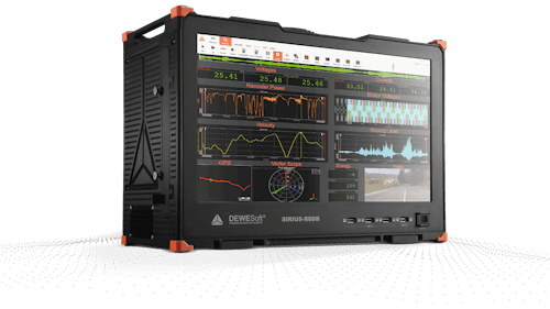
We recommend R3 DAQ system as a typical configuration for renewable energy measurements configured with:
6x high-voltage analog inputs
6x current analog inputs
1x low-voltage analog input for setpoint value
See and browse related and compatible data acquisition products.
The best AC⚡DC current sensor available today!
High-Accuracy Sensors for Current Measurement
EtherCAT Data Acquisition and Real-Time Control System
Data logger and embedded data acquisition system
Modular Data Acquisition (DAQ) System
High-Speed Data Acquisition (DAQ) System
Portable Data Acquisition (DAQ) Systems
High-channel-count data acquisition (DAQ) system
Award-Winning Data Acquisition and Digital Signal Processing Software
See and browse related and compatible testing solutions.

High-precision electrical power measurement and analysis [AC⚡DC]