


How Wireless Mesh Network (Mesh WiFi) Enables Remote Data Acquisition

May 3, 2021
As wireless technology grows at an exponential rate, many R&D engineers and managers performing test and measurement are eager to incorporate this cutting-edge technology into their workplaces and test tracks.
Introduction
Going wireless not only eliminates costly and sometimes fragile cables, but also allows test equipment in moving vehicles on land, sea, and air to maintain a constant connection back to computer clients for real-time data display and processing. Also, it allows the test equipment to be operated remotely when required. Test tracks, military proving grounds, and military and commercial airfields are prime candidates for the adoption of WIFI technology.
WIFI brings real convenience to mobile and remote applications, but it must also be accompanied by network security and “always-on” connectivity, to ensure that real-time data transfer and remote-control functionality are not compromised. This is where Mobile Mesh WIFI comes in.
WiFi mesh network
A wireless mesh network (WMN) is a communications network made up of radio nodes organized in a mesh topology. It can also be a form of wireless ad hoc network.


A mesh refers to the interconnection among devices or nodes. Wireless mesh networks often consist of mesh clients, mesh routers, and gateways.
Mesh clients are often PC laptops, cell phones, and other wireless devices. Mesh routers forward traffic to and from the gateways, which may or may not be connected to the Internet. The coverage area of all radio nodes working as a single network is sometimes called a mesh cloud.
Wireless mesh networks can self-form and self-heal. Wireless mesh networks work with different wireless technologies including 802.11, 802.15, 802.16, and cellular technologies and need not be restricted to any one technology or protocol.
Well-known for its portable Data Acquisition (DAQ) systems, Dewesoft pioneered remote control years ago, but it required a hard-wired connection because WIFI was unreliable enough when the test article was moving.
However, recently Dewesoft engineers have created a mobile WIFI mesh solution that allows their DAQ systems to “cut the cord” between their measurement systems and the computer, and maintain a constant, reliable, and secure data connection.


Allowing the computer host to be wirelessly connected to the test article provides some useful capabilities, such as remote real-time viewing and DAQ system control. This field-deployable Mesh WIFI network allows engineers to maintain live data streams in places like proving grounds, tracks, airfields, and testing grounds.
The implementation of a small base station and an unlimited number of WIFI Nodes allows a network to be mobile, scalable, and secure - all at the same time. In this article, we will describe exactly how this is done, and provide details about the wireless networking equipment that is behind it.
Technical overview
Most Dewesoft DAQ systems and data loggers use a Windows PC-compatible computer as a client that runs the DewesoftX DAQ software to display, store, and process the data. This computer usually also has a LAN and WIFI interface.
A second computer (and even more) can be connected via Ethernet/WIFI to the DAQ system, allowing remote control and data viewing and storage. The client computer(s) and the DAQ system(s) can be arranged in any one of three basic topologies:


In a wired scenario, there is very little danger of the connection being lost. But in a traditional WIFI environment, especially when the test article is changing directions and distance, and perhaps passing behind obstructions like walls, buildings, and the terrain itself, the chance of the connection being interrupted or even completely lost is very real.
With Dewesoft DAQ systems that have internal SSD storage, a connection loss does not result in the loss of any data, because it is always being stored locally on the DAQ system itself, and it can be reviewed later. However, the engineers operating the remote client(s) cannot see the test or control the DAQ system until the connection is restored.
This problem has been solved with the mobile Mesh WIFI data acquisition system. By adding interconnected WIFI nodes, a “mesh” of network connectivity is created, and the DAQ system is seamlessly connected via multiple paths back to the client computer, as long as the DAQ system stays within the mesh.
Applying the mobile mesh WIFI in a real test scenario
Let’s take a look at how Dewesoft engineers set up a multi-use track over the five square miles of the Utah Motorsports Complex located in Grantsville, Utah.


WIFI “heat maps'' show us how much WIFI coverage we have, allowing us to calculate how many WIFI Nodes should be added, and where. Concrete, buildings, trees, and other factors affect WIFI performance. Figure 3 shows the location of the base station and the coverage that a single WIFI node will provide:


The placement of the base station in the building area provides WIFI coverage to only a small portion of the track, as shown in Figure 3, so, we need to add WIFI nodes to create a “mesh” of coverage across the rest of the track:


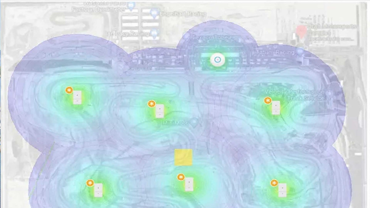
Figures 4 and 5 show the addition of two nodes and their effect on the network coverage. As the heat map shows, we can predict a range based on conservative estimates that are known with ideal conditions. The two nodes are showing a clear line of sight and a simple drop-and-go application. But with six nodes in total, it can create a network that covers the entire track.
When the test area is “line of sight," communication is easily accomplished with omnidirectional antennas. There are no obstacles to block the WIFI signals, and the mesh is complete. The test article with its onboard DAQ system can move freely anywhere within the mesh systems and will have an uninterrupted connection back to the client computer(s).
But, in the real world, there are usually at least a few obstructions to deal with. Walls, fences, tree lines, buildings, variations in the terrain - these obstructions will interfere with or completely block the WIFI. But using our heat maps we can determine where additional nodes are needed, and then add them.


When a 1.2 meter (four foot) high concrete wall is added to certain parts of the track, WIFI signals cannot pass through, creating coverage gaps. This is a more realistic expectation of what is seen in most applications. Notice the dead zones near the middle of the track in Figure 6.
When we add two nodes (circled in blue), the problem is solved, and the usable part of the track is fully covered again, as shown in Figure 7.
In nearly every setting there will be items (trees, walls, barriers, etc) that prevent an ideal WI-FI network. Our nodes are designed to be deployed quickly and easily inside these dead areas, to fill the gaps and maximize network coverage. The nodes receive and broadcast signals from each other, maintaining connectivity automatically.


The Mesh WIFI DAQ system is made up of:
Enterprise-grade networking equipment including a base station, access points, and antennas
A PC computer running DewesoftX software
Rugged and portable Dewesoft DAQ hardware
Any required sensors and their power supplies (if needed)
Let’s take a look at each of the major components.
The base station
The base station is the central point in which the data stream is viewed, controlled, and collected. Base stations can take on many forms, but there are two essential components:
The first is the control center which is a router, recorder, switch, and controller built into a single module that can be mounted in a standard 19” rack.
The second is the antenna that attaches to the controller providing the WIFI communications.
The equipment we selected for this application is the UniFi® Dream Machine Pro from Ubiquiti, Inc.


The base station controller’s main capabilities:
All-in-one 1U appliance for medium size networks
8-port Gigabit Switch with 1Gbps RJ45 and 10G SFP+ LAN
Dual WAN ports for redundancy and load balancing
Contains the UniFi OS with 8 port switch and built-in security gateway
Bluetooth connectivity for easy setup and access via the UniFI app
Scalable Network controller with advanced management capabilities
Supports Video direct input
Enterprise-class IPS/ IDS, DPI, and radio AI capabilities
1 x 1.3” touchscreen display for quick status information
1.7 GHz quad-core processor built-in
Using this controller, adding antennas is quick and easy. Multiple antennas, along with other devices like cameras, can be connected directly to the controller.
| Dimensions | Technical Specifications | Environmental |
|---|---|---|
| Dimensions W x H x D: 442.4 x 43.7 x 285.6 mm (17.42 x 1.72 x 11.24 in.) Weight: 3.90 kg (8.60 lb.) with mounting kits:3.99 kg (8.80 lb.) Package contents: 2 x Rackmount brackets 8 x Bracket screws 4 x Mounting screws 4 x Cage nuts 1 x Security screw 4 x 2.5” HDD screws1 x Power cord 4 x Rubber feet | Interfaces: 8 x 10/100/1000 RJ45 LAN ports 1 x 10/100/1000 RJ45 WAN port 1 x 1/10G SFP+ LAN port 1 x 1/10G SFP+ WAN port Management interfaces: Ethernet-in-Band1 x Bluetooth BLE Technical Information: IDS/IPS Throughput: 3.5 Gbps (measured with iPerf3) Processor: Quad ARM Cortex-A57 @ 1.7 GHzSystem Memory: 4 GB DDR4On-board FLASH Storage:16 GB eMMC | Operating Temperature: -10 to 40° C (14 to 104° F) Operating Humidity: 5 to 95% non-condensing Power: Max. Power Consumption: 33W Voltage Range: 100 to 240 V ACPower Method: 1 x universal AC input, 100 to 240 VAC, 50/60 Hz Redundant Power: 1 x RPS DC Input Power Supply: Internal 50W/12VESD/EMP Protection: Air: ±16 kV, Contact: ±12 kV Certification:CE, FCC, IC |
The controller includes software that allows easy management of switches and access points. If cameras are added to the system, they are also controlled, and their data is stored on an optional hard drive. Video data can be accessed remotely and securely.
Data and the network itself are protected in several ways:
Dual WAN with Failover: If the primary WAN connection drops, it will automatically switch to the other connection.
LTE Failover Redundancy: If the wired WAN fails, it will automatically switch to the UniFi LTE (this option and a US-based LTE account are required).
Power Supply Redundancy and Failover: If the internal power supply unit fails, the optional USP-RPS provides redundant power for backup.
Inherent security
The UDM Pro offers advanced firewall policies and persistent threat management to act as an Intrusion Prevention System (IPS) and Intrusion Detection System (IDS). Threat Management is easily selectable, and customized levels of security for viruses and malware, Point-to-Point (PtP) protection, hacking, internet traffic, and website reputation are available.
The network automatically scans clients connected to the network to identify potential security threats and vulnerabilities. Internal hardware and software can detect malware, worms, and other types of malicious traffic trying to scan the network.
DNS Content Filtering blocks traffic from sites with malicious, phishing, or adult content. There are three levels of DNS filtering security, each adding more protection. GeoIP Filtering can block outgoing, incoming, or bi-directional traffic designated by country and location, keeping the network local when required. The UniFi threat map allows the user to select the countries or locations they intend to block.
The UniFi controller is scalable and provides a range of management capabilities, including managing connected devices, network mapping, traffic management, and more. The network topology can be viewed and managed using the included software. It includes a Deep Packet Inspection (DPI) engine that tracks which applications and IP addresses are using the most bandwidth. Built-in analytics and reporting tools allow network engineers to manage even the largest populations efficiently.
Status information for every port can be viewed, including connection speed and duplex mode, TX/RX data rates, and Network/VLAN settings. All of these things are centrally controlled and managed using the included software. Additional capabilities include Auto-MDIX adjustment to straight-through or crossover Ethernet cables, 802.1X (RADIUS) authentication, and dynamic VLAN.
The MESH WIFI access point
The antenna consists of a single enterprise-grade Access Point (AP). The number of clients varies depending on individual bandwidth, but from experience, roughly 75 clients can be present on a single network in a typical Dewesoft DAQ application.
With multiple users, Multiple Input Multiple Output (MIMO), and a dual-radio capability, the data transfer is seamless and continuous with no user interaction required. The AP’s small 8.5 x 4 in. (216 x 102 mm) footprint is ideal for mobile applications.
This unit is also rated for outdoor use and includes a grommet sealing system for minimal water intrusion to connection points. A secondary port is available on all access points to allow wired bridging of the units. Each unit weighs 1.54 lbs. (0.7 kg), which allows for convenient mounting on the wall or small diameter poles. The operating temperature range is 14 to 158° F (-10 - 70 °C).


Up to eight networks can be supported with this system configuration allowing a single base station and antenna to support eight different standalone tests.
Base station conclusion
The combination of the controller and the antenna creates a base station. The base station provides the control and initial communications with the nodes and provides the range required to test across a large area.
The controller can easily be added to any standard 19-inch rack, occupying only one rack height unit. A single ethernet cable connects the antenna. This combination creates a small, agile base station perfect for any setting such as a van, mobile command unit, or base cell.


Mobile mesh nodes
Figure 13 below shows a portable, self-enclosed, WIFI-boosting mesh node that connects to the base station. The node contains an internal power source that will power the node for a full day without recharging (testing under minimal load has shown up to 3 days between charges) and has a recharge rate of 5 to 6 hours from complete discharge. This provides days of network boosting with minimal downtime.
The enclosure selected is a sealed waterproof housing with a handle and pass-through bulkhead connections for power and Ethernet (RJ45) connections. All node equipment is internally mounted and housed when not in use.
The WIFI mesh antenna can be fixed to the housing during use. This design allows the antennas to be externally mounted, improving signal quality. The dimensions of these nodes are:
Dimensions: 16 x 13 x 6.9 in. (41 x 33 x 17.5 cm)
Weight: approximately 15 lb. (~ 7 kg)

 in ready mode")
Inside the Mobile Mesh Node:
Power source
Required wiring (adapters, RJ45 cable)
Storage for additional ethernet cables and antennas
A PoE (Power over Ethernet) converter
Mesh router antenna
The power source


Goal Zero’s Yeti series power source was chosen due to its rugged nature, compact and lightweight design, battery performance, and product availability. They can be recharged from fully depleted within 5 hours.
The 200 Watt-hour power capacity has sustainable battery life for a day(or days) of testing as shown below. Solar panels can be added for improved battery life or recharging off-grid if necessary. An optional 500 Watt-hour unit and 1000 Watt-hour are available with a built-in pure sine wave inverter if needed.
Note that the host computer, if connected to the base station, is not included in the power calculations below (real-world run times are likely to be better than shown because these are maximum loading conditions):
| Power Consumer | Max. Power Consumption Rate | Continuous Run Time (200 Wh) | Continuous Run Time (500 Wh) | Continuous Run Time (1000 Wh) |
|---|---|---|---|---|
| Base Station Controller | 33W | 6.1 | 15.2 | 30.3 |
| Main Access Point Antenna | 9W | 22.2 | 55.5 | 111.1 |
| Node Access Point Antenna | 9W | 22.2 | 55.5 | 111.1 |
| Base and Main Access Point | 42W | 4.75 hours | 11.9 hours | 23.8 hours |
Learn more:
The antenna
A larger 3x3 MIMO dual-band antenna comes as standard, providing coverage with a 1000 ft. (304 m) range. The antenna is external to the case and is designed for pole or case mounting. Its IP67 environmental rating means that it can withstand dust, rain, and other elements. Simply connect the cable to the case pass-through and the larger antenna will power itself on, automatically establishing a connection.


The “bridging” option allows multiple antennas to be connected via RJ45 cables. This expands the base station’s broadcast and transmission capabilities using the same power source.
Basic Specifications:
Environment: Outdoor
Simultaneous dual-band performance
2.4 GHz radio rate: 450 Mbps
2.4 GHz MIMO: 3 x 3
5 GHz radio rate: 1300 Mbps
Includes secondary Ethernet port
POE (Power over Ethernet) mode: 802.3af
Mounting: Pole or wall
UAP-AC-PRO Specifications
| Parameter | Specification |
|---|---|
| Dimensions | 196.7 x 196.7 x 35 mm (7.74 x 7.74 x 1.38 in.) |
| Weight | 350 g (12.4 oz.)With mounting kits: 450 g (15.9 oz.) |
| Networking Interface | 2 x 10/100/1000 Gb Ethernet ports |
| USB | 1 x USB 2.0 interface |
| Buttons | RESET |
| Power Method | Passive Power over Ethernet (40 V), 802.3af/802.3at Supported(Supported voltage range: 44 to 57 VDC) |
| Power Supply | UniFi Switch (PoE) |
| Power Save | Supported |
| Max. Power Consumption | 9 W |
| Max. Tx Power | 22 dBm @ 2.4 GHz, 22 dBm @ 5 GHz |
| Antennas | 3 x Dual-band Antennas, 2.4 GHz: 3 dBi, 5 GHz, 3 dBi |
| Wi-Fi Standards | 802.11 a/b/g/n/r/k/v/ac |
| Wireless Security | WEP, WPA-PSK, WPA-Enterprise (WPA/WPA2, TKIP/AES) |
| BSSID | Up to 8 per radio |
| Mounting | Wall and Ceiling mounting kits included |
| Operating Temperature | -10 to 70° C (14 to 158° F |
| Operating Humidity | 5 to 95% Non-condensing |
| Certifications | CE, FCC, IC |
Advanced Traffic Management
| Parameter | Specification |
|---|---|
| VLAN | 802.1Q |
| Advanced QoS | Per-User Rate Limiting |
| Guest Traffic Isolation | Supported |
| WMM | Voice, Video, Best Effort, and Background |
| Concurrent Clients | 250+ |
Supported Data Rates (MBps)
| Parameter | Specification |
|---|---|
| 802.11ac | 6.5 to 1300 Mbps (MCS0 - MCS59 NSS1/2/3, VHT 20/40/80) |
| 802.11n | 6.5 to 450 Mbps (MCS0 - MCS23, HT 20/40) |
| 802.11a | 6,9,12,18,24,36,48,54 Mbps |
| 802.11g | 6,9,12,18,24,36,48,54 Mbps |
| 802.11b | 1, 2, 5.5, 11 Mbps |
How the mesh network works
The base station is the central point in which all control and data flow. The nodes serve as wireless amplifiers for the network, allowing data to be relayed from the test article back to the base station. Stand-alone units can be dropped anywhere within the test area once communication is established.
The software informs the operator if a range is exceeded. We found that 400 feet (122 m) from the base to the first node, then 1000 feet (305 m) between successive nodes worked as a maximum reliable range. Data throughput and overall connectivity can be monitored easily within the controller software.
Nodes can be “paired” with the network by connecting a physical cable for three minutes. This adaptation prevents cross-talk and ensures that only wanted nodes are assigned to the network. Using this method, multiple base stations and networks can operate within the same space, allowing an infinite amount of mesh networks to operate securely. Only nodes assigned to the network will relay network data. This concept is beneficial for test tracks because it allows multiple tests to be accomplished without the constraints of a single network.
Security
The Unify PRO controller provides advanced firewall policies and persistent threat management. It acts as an Intrusion Protection System (IPS) and Intrusion Detection System (IDS).
Operators can select and customize levels of security for viruses and malware, Point-to-Point (PtP) protection, hacking, IP traffic, and website reputation. It automatically scans clients (aka “endpoints”) connected to the network to identify potential threats and vulnerabilities.
It also includes “honeypot” functionality to detect malicious traffic and keep them away from critical systems. Three layers of DNS content filtering block traffic from malicious actors and block unwanted content. Finally, GeoIP filtering allows the operator to block incoming, outgoing, or bi-directional traffic designated by country.
Delivery
Dewesoft puts together complete systems for testing applications, including all of the DAQ equipment as well as all elements of the Mesh network. We manufacture the DAQ system and purchase all third-party products, assemble everything including mounting them in racks and rugged cases, and interconnect everything.
All items are enclosed within a high-impact shipping case designed to handle the abuse of shipment and field deployments. Then we test the entire system and ensure that everything works perfectly.
All software comes pre-configured with the networks established and name/password included on the front cover of the controller. The only power is required to activate everything and open the network.
Custom solutions are available to any customer with the proper IT training. The UniFi quick start guide shows how to access the controllers and create/delete or modify the settings as required.
Article under test
The design of this mesh WIFI is that the base station and the deployed nodes are doing the heavy lifting. The article under test only needs to connect and maintain the connection.
Dewesoft measurement computers like the KRYPTON CPU and SBOX data processing computers have a built-in wireless card that can access the network. Data is streamed through the controller onto the network and back to the base station.


Network pptions
The focus of this application was to create a stand-alone network that would auto-assign IP addresses, making network setup fast and easy. The controller’s internet connection inputs include an adapter that allows cellular network data to be input, along with any traditional internet provider.
This feature allows data transfer from remote locations to a central server. Users are free to set up this feature according to their own needs, with their existing company servers.
Options
Options like GPS tracking can be built-in, allowing traceability and location services for each node. With the versatility of this equipment, options like directional antennas in lieu of omnidirectional versions can provide longer ranges with the same node.
Brackets are also available, allowing any or all parts of the system to be hard-mounted. The base station is currently designed to be installed into an environment with power and infrastructure to support it, however, it is possible to provide a battery-powered stand-alone base station. Regenerative solar charging is also a popular and useful option, especially for remote locations. Each application is different, and Dewesoft has the capability of addressing each one individually.
For high power applications, the optional Rocket radio with a sectoral antenna allows for 90° of 5 GHz data only, at a range of more than 0.75 miles (1.21 km). The radio and antenna can be powered from the node cases via PoE and 110 V with the case providing the storage for the radio, wiring, power source with the antenna stored externally.


Summary and conclusion
“Cutting the cord” by eliminating expensive and sometimes fragile wires makes setting up and conducting testing easier, less expensive, and more reliable. As a major manufacturer of data acquisition systems, this has been a Dewesoft prerogative for many years.
In this application we were able to achieve 1300 Mbps of wireless data flow, facilitating high-speed test track data acquisition across a complex three-dimensional environment. We now share this approach freely in the hope that it will assist the test and measurement community.
The solution can easily be compatible with and extend into WiFi 6 mesh networks.
Citations and trademarks
Ubiquiti, Ubiquiti Networks, the Ubiquiti U logo, the Ubiquiti beam logo, and UniFi are trademarks or registered trademarks of Ubiquiti Networks, Inc. in the United States and other countries. Specifications and images of the Ubiquiti products included in this article are the copyrighted property of Ubiquiti Networks, Inc.
Specifications and images of the YETI 200X Power Source are the copyrighted property of GOAL ZERO LLC.
Microsoft® and Windows® are registered trademarks of Microsoft Corporation in the United States and/or other countries.
Dewesoft®, KRYPTON®, SIRIUS®, and IOLITE® are registered trademarks of Dewesoft d.o.o.
All other trademarks are the property of their respective owners.