




Testing a Second-Life Nissan Leaf Battery Pack for Stationary Storage
Alexander Rink
Tallinn University of Technology (TalTech)
July 24, 2026
Repurposing electric vehicle batteries offers a practical way to extend their value beyond automotive use, but their condition must be carefully verified before deployment. This case study evaluates a second-life Nissan Leaf battery pack by monitoring its charging behavior, voltage limits, and internal data. Using the Dewesoft Obsidian R8, the study demonstrates a reliable method to assess safety and performance before integrating the battery into a DC microgrid.
Why second-Life EV batteries need testing
Electric vehicles (EVs) are becoming increasingly common, but their lithium-ion batteries have a limited service life in automotive use. Once a battery pack falls to around 70 to 80 percent of its original capacity, it may no longer meet the demands of a vehicle. However, it can still be suitable for less demanding applications, such as stationary energy storage.
Before reuse, the battery must be carefully tested because its actual condition may be uncertain and hidden damage may be present. Repurposing used EV batteries can therefore extend their useful life, reduce waste, and provide a valuable second use.
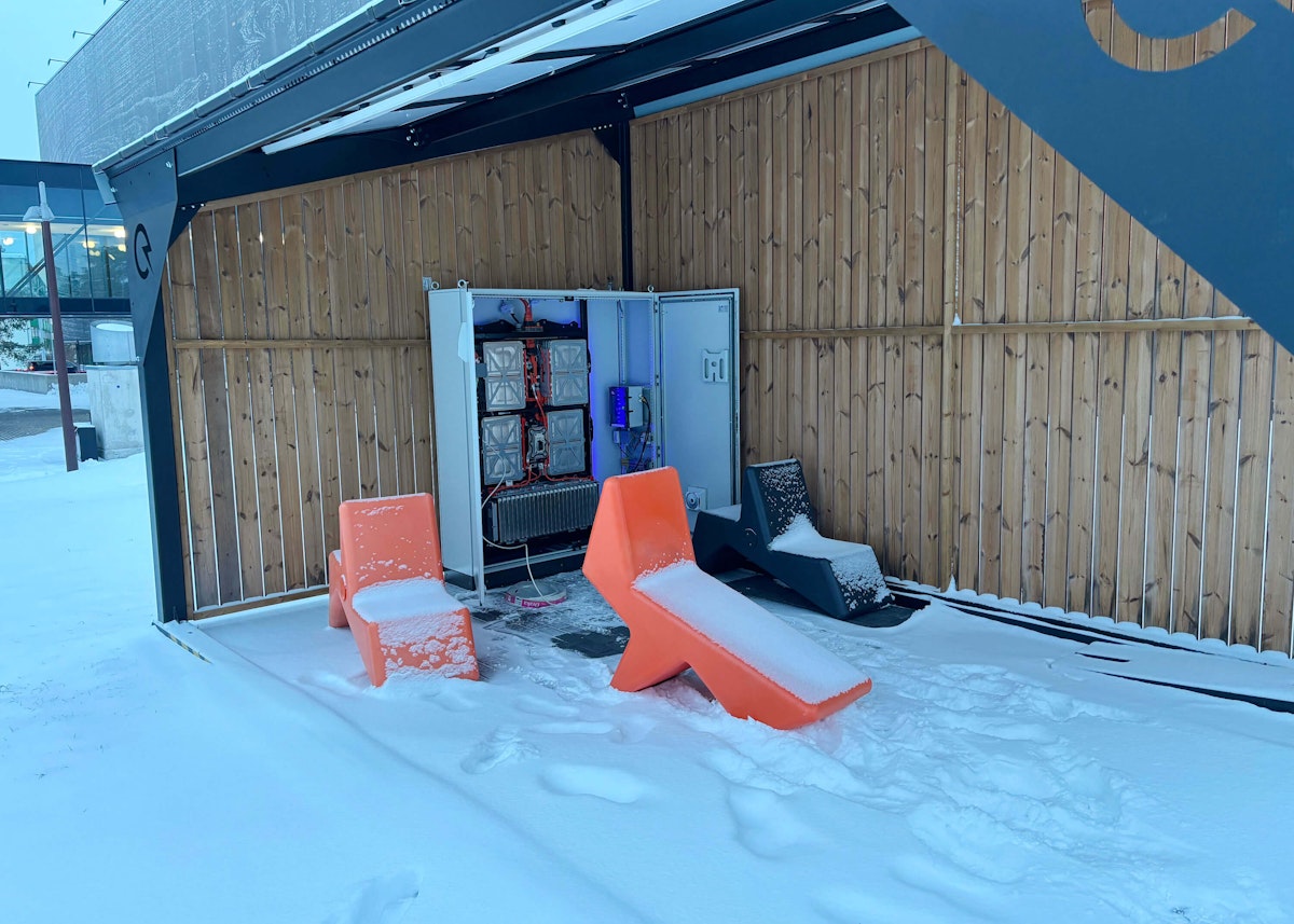
I tested a 24 kWh Nissan Leaf battery for possible use in Tallinn University of Technology’s (TalTech’s) local DC microgrid. Before connecting the battery to the grid as a stationary storage unit, its charging behavior had to be monitored to confirm that it operates safely and within a suitable voltage range. For this task, the Dewesoft OBSIDIANR8 data logger was used to record the battery charge cycle and its CAN data.
Second-life EV batteries for stationary energy storage
Growth in EVs and energy-storage demand
The rapid growth of electric vehicles is closely linked to climate policy and the broader electrification of transport. In Europe, the European Green Deal is helping drive the transition toward climate neutrality and deeper emissions reductions [1]. Globally, EV adoption is also accelerating. According to the International Energy Agency (IEA), more than 17 million electric cars were sold in 2024, representing over 20 percent of all new car sales [2].
At the same time, the expansion of renewable energy is increasing demand for battery storage. The IEA expects renewables to supply 43 percent of global electricity by 2030, while the share of variable sources such as solar PV and wind is projected to nearly double to 27 percent [3]. Supporting this shift will require global energy storage capacity to grow sixfold to 1,500 GW by 2030, with batteries accounting for around 90 percent of that increase [4]. This trend is already visible in the market, where demand for stationary battery storage has grown by more than 60 percent per year over the past two years [5].
These developments create a strong case for repurposing used EV batteries as stationary energy storage. Retired battery packs often retain 70 to 80 percent of their original capacity, which can make them suitable for applications such as renewable energy buffering, peak shaving, and backup power [6]. However, they cannot be reused safely without proper evaluation. Their operating history may be incomplete, and hidden damage or uneven cell degradation may be present, so both technical and safety assessments are essential before deployment.
The potential value is considerable. A second-life EV battery may remain useful in stationary storage for up to another ten years after its automotive service [7]. In this way, second-life batteries can help address two challenges at once: the growing number of retired EV battery packs and the increasing need for energy storage in renewable power systems.
TalTech’s Power Electronics Research Group is currently investigating the use of second-life EV batteries in a local DC microgrid. As part of this work, a Nissan Leaf battery pack is being tested to determine whether it can operate safely and reliably as a stationary storage unit. The Dewesoft Obsidian R8 was selected for data logging because it combines accurate high-voltage and low-current measurements with CAN connectivity for reading battery management system data directly from the pack.
Battery safety and operating range objective
Verifying battery safety before grid integration
The goal of this project was to evaluate a second-life 24 kWh Nissan Leaf battery pack before integrating it into TalTech’s local DC microgrid. The microgrid combines on-site solar generation with DC loads, and the battery is intended to support peak shaving, load shifting, and emergency backup. Before permanent installation, it was necessary to confirm that the pack could operate safely, remain within an appropriate voltage range, and avoid excessive degradation.
A previous test had already identified a narrower voltage window for battery operation. My task was to verify this range by recording a complete charging cycle and analyzing individual cell voltages, total pack voltage, charging current, and energy input. I used the Dewesoft Obsidian R8 data logger with plug-and-play signal-conditioning modules to measure high voltage and current while simultaneously decoding BMS CAN messages with a custom C++ script.


Battery test setup and data acquisition
Battery pack and BMS CAN connection
Figure 2 shows the electrical measurement setup used for the battery charging test.


A key part of the setup is the communication between the battery pack BMS and Dewesoft OBSIDIAN R8 data logger.
BMS CAN is connected to the CAN1 port of the OSBDIAN R8 through a twisted CAN pair. This connection is especially important because it allows the Obsidian to record BMS data directly from the battery pack during the charge cycle.
High-voltage and current measurement
At the same time, the Nissan Leaf battery pack (BAT_1) is connected to the bidirectional power supply (PSU_1), with the battery's positive terminal passing through the DSLi-20A current-measurement adapter before reaching the power supply. In contrast, the battery's negative terminal is connected directly.
I measured battery voltage across the battery terminals with Kelvin wires using the multi-channel amplifier module IOLITEir HV input on the OBSIDIAN. I measured the charging current through the DSLi-20A adapter and routed it to the OBSIDIAN via the DSUB9 input.
The OBSIDIAN R8 was well-suited for this work because it enabled the most important battery measurements to be collected in a single system.
In this project, the main advantage was its ability to record BMS CAN data together with direct electrical measurements. This made it possible to monitor not only the battery pack voltage and charging current but also the BMS's internal data during the charge cycle.
In addition, Dewesoft's integrator math function was useful for calculating the energy flowing into the battery pack during charging.
The battery was charged using an ITECH IT6012C-500-80 bidirectional power supply. It was a suitable choice for this project because it can be programmed to switch between constant-current (CC) and constant-voltage (CV) modes.
Second-life battery charging test procedure
The test procedure followed these steps:
Pre-test check: Before starting the charging test, I used the Dewesoft Obsidian R8 to read the battery BMS CAN data in real time. By that stage, I had already decrypted the most important CAN messages, so part of the software setup was complete. This allowed me to check whether any clear fault or abnormal condition was present before charging, for example, unusually low or high cell voltages or other suspicious values in the BMS data.
Hardware setup: I connected the Nissan Leaf battery pack to the Dewesoft Obsidian R8 measurement system and to the bidirectional power supply. The battery pack voltage was measured through the IOLITEir HV input, the charging current was measured using the DSLi-20A adapter, and the battery BMS data was read through the CAN1 port of the Obsidian.
Software setup: In DewesoftX, I configured the voltage, current, and CAN1 measurement channels. The standard Nissan Leaf DBC database did not meet my needs, so I used a custom C script inside Dewesoft to decode the CAN messages into a human-readable form. Using the C script was really straightforward and made my life much easier. I then used the measured battery voltage and charging current to derive a mathematical integrator formula to calculate the energy flowing into the battery pack during charging. I also set up the data storing process so that only the most relevant signals were recorded and stored: battery voltage, charging current, cell voltages, calculated energy, and estimated the State of Charge (SoC) - the level of charge relative to capacity, expressed as a percentage.
Charging procedure: The battery was charged from 360 V to 395 V in constant current mode at 10 A. The power supply was programmed to switch automatically from constant-current to constant-voltage mode at 395 V, after which charging continued until the current dropped to 5 A. During the full charging process, DewesoftX recorded the measured voltage and current, calculated the energy, and decoded the BMS CAN data.
Data export and analysis: After the test, I exported the recorded data in MATLAB file format (.mat) for further analysis. The exported data was then processed in MATLAB to generate the plots used later in the results section.
During the charging test, I used a simple measurement layout in DewesoftX to monitor the battery in real time (Figure 3). The main part of the screen was dedicated to the individual cell voltages, displayed as separate digital meters. This overview made it easy to quickly compare the cell voltages and notice any abnormal or outlying values during charging. On the right side of the screen, the battery pack voltage and current were displayed using analog gauges, providing a clear overall view of the pack-level charging behavior.


Battery test results and operating-range analysis
Cell-voltage safety across 96 cell groups
Figure 4 shows the voltages of all 96 cell groups across the narrowed state-of-charge range used in the test. The key result is that every cell remained within a safe voltage range throughout the full charging cycle.
A 2024 study of first-generation Nissan Leaf batteries used a cell-voltage range of 2.8 to 4.2 V [8]. In this test, the lowest cell voltages were about 3.55 V at the start of charging, while the highest reached only 4.10 to 4.11 V at the end. These values remained well above the lower limit and comfortably below the upper limit.
The selected pack voltage range of 360 to 395 V was therefore conservative and safe. No cell group approached overvoltage or undervoltage. The largest difference between individual cell voltages appeared at low state of charge. As charging continued, the cell voltages became more closely grouped.
Because none of the cells entered a critical region, the battery may still have some usable capacity below the current lower voltage limit. However, this should be confirmed through further discharge testing before the operating range is expanded.


Figure 5 shows battery capacity, pack voltage, and pack current across the selected state-of-charge range. The clearest feature is the transition from constant-current (CC) to constant-voltage (CV) charging, marked by the red vertical line.
During the CC stage, the charging current remains stable at 10 A. After the transition to CV charging, the current gradually decreases to 5 A. Once it reached 5 A, the charging process was intentionally stopped.
The pack voltage rises quickly at lower state-of-charge values and then begins to level off as it approaches the upper voltage limit. This is typical lithium-ion battery behavior. Meanwhile, the stored energy continues to increase throughout the test, reaching about 9.4 kWh by the end of the selected operating range.
A significant share of this energy is stored during the CC stage. At the CC-to-CV transition, the battery had already received approximately 6.3 kWh, which is about two-thirds of the total energy added during the test. The battery continues to gain energy during the CV stage, but more slowly as the charging current decreases. This means that the upper part of the voltage range still adds useful capacity, although charging becomes less time-efficient.
The state-of-charge axis in Figure 5 represents only the selected 360 to 395 V operating window. It does not show the full BMS state-of-charge range of the battery pack. Therefore, the CC-to-CV transition at around 60 percent refers to 60 percent of the selected test window, not 60 percent of the battery’s full usable capacity.


Conclusion: suitability for stationary energy storage
This work demonstrated that the condition of a second-life Nissan Leaf battery pack can be effectively evaluated with the Dewesoft Obsidian R8 before the pack is reused as a stationary energy storage unit. The measurement setup recorded BMS CAN data together with direct measurements of pack voltage and charging current. Dewesoft’s integrator math function was also used to calculate the energy transferred into the battery during charging, providing a clear view of both its electrical performance and internal behavior.
Safe cell voltages and remaining capacity
The results confirmed that the selected operating range of 360 to 395 V was safe for this battery. All 96 cell groups remained within safe limits throughout the charging cycle. The lowest measured voltages were about 3.55 V, while the highest reached only 4.10 to 4.11 V.
The analysis also showed that the lower voltage limit was conservative. None of the cell groups approached undervoltage, which suggests that some usable capacity may remain below the current lower limit. This should be confirmed through additional discharge testing.
The charging profile was stable and typical for a lithium-ion battery. The current remained constant at 10 A during the constant-current stage, then gradually decreased to 5 A during the constant-voltage stage. By the end of the test, the battery had stored about 9.4 kWh within the selected operating window. Approximately 6.3 kWh of this energy had already been added before the transition from constant-current to constant-voltage charging.
Overall, the battery behaved in a stable and predictable manner within the selected voltage range. The results support further evaluation of the pack for second-life stationary energy storage. Future work should include deeper discharge testing and repeated cycling to determine the most suitable long-term operating range.
References
“The European Green Deal - European Commission.” Accessed: Mar. 31, 2025. [Online].
“Global EV Outlook 2025,” 2025.
“Renewable electricity – Renewables 2025 – Analysis - IEA.” Accessed: Apr. 14, 2026. [Online].
“Outlook for battery demand and supply – Batteries and Secure Energy Transitions – Analysis - IEA.” Accessed: Apr. 14, 2026. [Online].
“The battery industry has entered a new phase – Analysis - IEA.” Accessed: Apr. 14, 2026. [Online].
“Challenges and opportunities for second-life batteries: Key technologies and economy - ScienceDirect.” Accessed: Apr. 14, 2026. [Online].
“Second-life EV batteries for stationary storage applications in Local Energy Communities - ScienceDirect.” Accessed: Apr. 14, 2026. [Online].
“Evaluation of the second-life potential of the first-generation Nissan Leaf battery packs in energy storage systems - ScienceDirect.” Accessed: Apr. 23, 2026. [Online].