


CNC Machining Process Instrumentation for Hands-On Engineering Education
University of Bordeaux
June 2, 2026
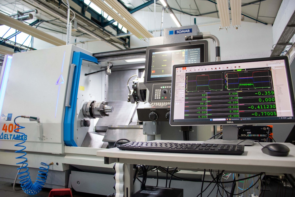
At the University of Bordeaux, students in the Master’s degree in Mechanics, Mechanical Engineering track, and doctoral programs study advanced manufacturing processes with a particular focus on machining. The program combines theory with hands-on experimentation to help students understand the physical phenomena behind cutting operations and optimize industrial processes through the analysis of mechanical actions, cutting forces, torque, and energy consumption. Dewesoft data acquisition systems, together with a range of external sensors, are used to instrument CNC machine tools and give students synchronized, real-time insight into actual machining performance.
Introduction
Machining processes are central to modern manufacturing, where productivity, part quality, and sustainable performance depend on a deep understanding of cutting phenomena, energy flows, and machine-tool interactions. For universities, teaching these processes effectively requires more than theory. Students must be able to observe real machining operations, measure the forces and energy involved, and analyze process behavior under realistic industrial conditions.
The University of Bordeaux and its Institute of Technology (IUT) have strengthened hands-on teaching and research in machining processes by systematically equipping industrial CNC machine tools with instrumentation.
By combining machine-control data with external mechanical and electrical measurements, the University of Bordeaux gives students and researchers a synchronized view of the machining process. This makes it possible to analyze cutting forces, mechanical power, and electrical energy consumption in real time, and to connect these measurements directly with operating parameters such as cutting speed, feed rate, depth of cut, tool geometry, and machining strategy.
The University of Bordeaux uses this instrumentation platform throughout its mechanical engineering curriculum, from the University Technical Diploma (BUT) and Master’s programs to doctoral research. For undergraduate and Master’s students, it supports hands-on, skills-based learning in process industrialization and optimization. For doctoral researchers, it provides the measurement framework needed to develop predictive models and real-time control strategies for improving surface quality, energy efficiency, and manufacturing performance.
The issue
Through the University Technical Diploma, the IUT has strengthened its focus on innovative academic and technical teaching. The program combines a skills-based learning approach with greater access to professional experience, including company placements, internships, and work-study opportunities.
In the field of teaching and research in machining, the main challenge is the evolution of mechanical engineering programs, particularly the Master's in Advanced Industrialization. The challenge is to align with future industry requirements by focusing on advanced machining and its optimization.
Mechanical instrumentation, measurement of cutting actions/forces/torques, and analysis of power consumption are essential. When combined with other data, such as the thermal field, they provide an in-depth understanding of machining operations and their optimization. The aim is to improve the quality of parts produced and reduce environmental impact.
The distinctive Bordeaux approach is rooted in its core expertise in machining optimization. In close collaboration with the I2M laboratory's research activities, the university integrates multiphysical measurements, including force/torque, electrical power, and thermal measurements, to enable a comprehensive process analysis.
The I2M Institute of Mechanics and Engineering covers the entire spectrum of solid, fluid, and energy mechanics. The institute draws on theoretical approaches across different scales of observation, advanced experimental methodologies, and the development of numerical methods for high-performance computing.
This joint approach demonstrates how synchronized multi-source instrumentation enables students to link machining physics, energy consumption, and process optimization across Bachelor, Master, and PhD levels.
The studies
The studies with a hands-on approach focus on the machining process and use three primary data sources:
mechanical actions,
mechanical power, and
electrical power consumption.
This focus enables the determination of the influence of operating parameters (cutting speed, feed rate, depth of cut, cutting tool geometry, machining strategy, etc.) on these energy variables during cutting. We base several case studies on these experimental configurations for traditional student training and for research-based doctoral student training.
For third-year Bachelor's and first-year Master's students in Mechanical Engineering, the aim is to take an experimental approach to the industrialization of a part machined on industrial CNC machine tools: designing the manufacturing process using a CAM tool, developing cutting conditions, starting the manufacture of a metal part, and producing a small series of parts.
In this context, the objectives of the measurements taken are to compare the mechanical power consumed to perform the same machining operation:
With different drill bit geometries,
With different 3- and 5-axis machining strategies.
In the second year of the Master's program, students' work enables them to optimize tool selection and cutting conditions based on parameters such as energy consumption, surface finish, and chip morphology, for example, through machine-tool instrumentation and analysis of the parts produced.
Students perform the required machining tests in accordance with the Tool Torque Material standard, COM NF E66-520-1 to 8. The objective is to determine the optimal cutting conditions for turning a steel part. To do this, they use the optional AMC3 software module integrated into the machine tool’s numerical control system. AMC3 supports different types of sensors and measurements, including electrical and mechanical data from internal machine signals, an external wattmeter, or a dynamometer.
This setup allows AMC3 to estimate cutting forces and specific cutting pressure during a single machining operation. To compare these results and deepen the understanding of the machining process, students also evaluate mechanical power using measurements from a KISTLER 9129AA dynamometer platform and a Dewesoft data acquisition system. At the same time, Dewesoft records the cutting and feed-rate data controlled and generated by AMC3, together with additional measurements, to provide a more complete analysis of the process behavior.


For doctoral students, the work focuses on optimizing the overall manufacturing process, with particular attention to surface quality and environmental performance. Their research aims to develop models that describe how the material state changes during different manufacturing steps, including WAAM, heat treatment, and machining. These models are identified and validated using process-specific instrumentation and post-process analyses.
Another important research area is the dynamic control of machining operations. During machining, students work to identify process models in real time so they can determine the actual state of the system as manufacturing takes place. Based on this information, the optimal control strategy can be adjusted in real time to improve dynamic behavior and energy performance, even when cutting conditions vary or disturbances occur.


Test and data acquisition equipment
A unified measurement environment based on Dewesoft data acquisition systems, OPC-UA communication, and dedicated mechanical and electrical sensors can serve both pedagogical and research objectives.
Figure 3 shows the synchronization between the equipment and the Dewesoft sensors, enabling the setup of a measurement system based on sensor data.


We have equipped the machining equipment with three devices to characterize the energy variables involved in a machining operation. Each device includes a professional license for DewesoftX data acquisition software.
DewesoftX OPC-UA client plugin: The OPC-UA Client plugin enables DewesoftX to acquire data from any 3rd-party OPC-UA server or a DewesoftX OPC-UA server. The system receives all the data as asynchronous channels.
SIRIUSi-8xSTMG and SIRIUSi-HS-4xHV-4xLV data acquisition systems: SIRIUS modular is a versatile and robust data acquisition system. SIRIUS provides high-end signal-conditioning amplifiers for almost any signal or sensor.
Dewesoft DS-CLAMP-150DC Current Clamps: AC/DC current clamps.
KISTLER 9129AA Dynamometer Plate
This solution, with synchronized multi-source measurements, can enhance students’ understanding of machining physics while providing a robust experimental framework for advanced research in energy-aware, digitally assisted manufacturing.


Instrumentation and measurement setup
The first source of information is the OPC-UA server hosted on the machine's numerical control. This server provides information about the machine's status, including the positions, speeds, accelerations, torques, and powers of each axis for linear motion and spindle rotation. The measurement is integrated into Dewesoft using the OPC-UA client plugin.
The second measuring device is a 6-component dynamometer used to characterize mechanical cutting actions. It is a KISTLER type 9129AA platform capable of measuring forces up to 10 kN and torques up to 500 Nm. This sensor couples with its amplification system. We use a SIRIUS modular system equipped with STMG amplifiers configured in analog mode to measure voltages in the ±10V range.
These two measurement systems enable the mechanical power generated by cutting to be calculated mathematically.
The third measurement system combines a modular SIRIUS system with the "Power Analyzer" module, featuring four high-voltage and four low-voltage analog channels. To measure voltage, three high-voltage channels are connected either directly to the machine's power supply or after the power converter that controls the main spindle motor. To measure current, we connect the three DS-CLAMP-150DC current clamps in parallel to the three low-voltage channels. The Power Analyzer module determines the electrical power consumed by the machine tool.
DewesoftX software (version 2025.2) displays real-time values for various physical quantities, including mechanical actions, positions, speeds, spindle torque, mechanical power, and electrical power. Figures 5, 6, and 7 give some examples. This configuration provides a comprehensive, synchronized view of the cutting process's performance characteristics during machining.


Test results and data analysis
For applications involving the turning process, in the signal acquisition analysis, the first step is to zero the signals during the phase when the measurements do not correspond to the cut.


The analyses then focus on the cutting zone (see Figure 7). We conduct the tests on AISI 4140 steel. The cutting tool consists of a TNMG 16 04 08-PR 4225 (SANDVIK) insert and a PTGNL 2020K16 (SANDVIK) insert holder. The operating conditions are as follows:


The results show a strong correlation between the dynamometer power readings and the electrical measurements. The power reading from the OPC-UA server is slightly under the rate. We determine this based on the torque and rotational speed of the main spindle: Pc=C. Note that the torque value is data provided by the controller and does not guarantee calibration by the machine manufacturer.


As before, in milling applications, the first step is to reset the signals to zero during the phase when the measurements do not correspond to the cut. It is also necessary to filter out the system's natural frequency, which can cause parasitic oscillations during acquisition.


Measurements taken during the cutting phase using the 6-component dynamometer (Figure 12) and signals from the various spindle and axis motors (Figure 13) enable comparison of mechanical and electrical power (Figure 14).


The electrical power is higher than the mechanical power in the figure above because it includes the power consumed by the machine tool when idle and during machining. In addition, numerous peaks in electrical power are due to successive motor accelerations, which the calculation of instantaneous power does not account for.
Thus, comparable developments in these two power calculations will eventually enable the removal of the dynamometer plate and the direct use of signals from the various spindle and axis motors to calculate the machine tool's instantaneous power consumption during machining. This information will enable real-time optimization of cutting parameters for machining.
Key innovations of the teaching and research platform
This teaching and research platform introduces an integrated approach to machining instrumentation that combines mechanical, kinematic, and electrical measurements within a single, synchronized acquisition environment. By coupling internal numerical control data accessed via OPC-UA with external force, torque, and power sensors, the system provides a comprehensive, multi-physics view of machining operations under realistic industrial conditions.
Our setup combines:
OPC-UA machine data
External dynamometer
Electrical power measurement
Unified Dewesoft environment
Pedagogical + research integration
A central contribution of this work is the direct comparison between mechanical cutting power and electrical power consumption. This dual analysis enables both students and researchers to distinguish between sound cutting energy and total machine energy usage, highlighting the influence of machine dynamics, auxiliary systems, and transient operating phases. It also provides a robust experimental basis for validating power estimation models derived from controller data.
The platform further supports a progressive reduction of intrusive instrumentation. Once validated, correlations between mechanical and electrical indicators enable direct estimation of cutting power and energy consumption from machine and motor signals, paving the way for non-intrusive, industrially deployable monitoring solutions.
A distinctive aspect of the approach is the use of a single experimental framework across bachelor's, master’s, and doctoral training. This continuity reinforces skills-based learning and directly links education to active research in process modeling, energy efficiency, and real-time control. Beyond turning and milling, the system's modular architecture enables straightforward extension to other manufacturing processes, supporting scalable energy-aware machining analysis aligned with current digital manufacturing and sustainability objectives.
Conclusion
The studies and findings from the above applications enable us to develop predictive models of power consumption during machining operations. They also help us understand phenomena in the cutting process and identify the underlying physics.
It is thus possible to extend the analyses to a broader range of operating parameters by varying cutting parameters (cutting speed, feed rate, depth of cut, cutting tool geometry) and the machined material, and to study the effect of lubrication, for example.
This experimental device enables the development of teaching sequences using methods tailored to students' skills, thereby promoting learning and cutting-edge research by simplifying comparisons of multiple physical quantities within a single software environment.
Our work contributes to hands-on machining education, energy-efficient CNC machining, and Industry 4.0 manufacturing through real-time process monitoring and integrated data acquisition.
Team
Professor Olivier Cahuc
Teaching Researcher Jean-Yves K’Nevez
Mechanical Engineering Instructor Gaëtan Albert
Professor Raynald Laheurte
Associate Professor Maël Jeulin
Senior Lecturer Sana Werda
PhD Students Philippe Darnis, Jamy Vignaud, and Antoine Laffitte
References
M. Jeulin, O. Cahuc, P. Darnis, et R. Laheurte, “A 6-component mechanistic model of cutting forces and moments in milling”, Forces in Mechanics, vol. 9, pages 100-130, December. 2022.
O. Cahuc, C. F. Bisu, A. Gérard, P. Darnis, et R. Laheurte, “Correlation between Torsor Measurements on the Chip Orientation”, Advanced Materials Research, vol. 698, pages 79-88, 2013.
G. Albert, R. Laheurte, J.-Y. K’Nevez, P. Darnis, et O. Cahuc, “Experimental milling moment model in orthogonal cutting condition: to an accurate energy balance”, The International Journal of Advanced Manufacturing Technology, vol. 55, no 9-12, pages 843-854, August 2011.