




Climate Chamber Testing of a 320 kW DC Fast Charger

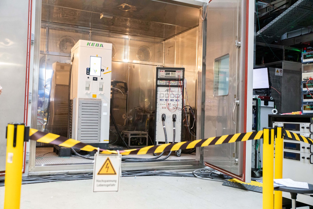
High-power DC charging stations must deliver reliable performance even under extreme environmental conditions. To validate thermal behavior and power derating strategies at elevated ambient temperatures, KEBA subjected its flagship DC fast charger to comprehensive testing in a climate chamber. The tests were conducted at the AIT (Austrian Institute of Technology) using controlled load scenarios and Dewesoft's high-precision power measurement and analysis.
Introduction
To verify the behavior of high-power DC charging stations under elevated ambient temperatures (such as those encountered in southern latitudes) engineers at KEBA conducted load tests in environmental test chambers at an accredited Austrian testing institute.
KEBA specializes in innovative AC & DC charging solutions for electric vehicles. The development focuses on scalable, robust, and user-friendly designs. The goal is to accelerate electric mobility in private, industrial, commercial, and public environments through robust, future-proof charging solutions, thereby contributing to a sustainable mobility transition.
Why DC fast chargers require climate testing
Extreme climate directly affects the performance, reliability, and lifespan of EV charging stations.
Effects of high temperatures
High temperatures can trigger power derating, accelerate component aging, overheat connectors and cables, impair displays, and increase grid-interaction challenges.
Effects of low temperatures
Low temperatures may limit charging power, stiffen cables and connectors, increase the risk of condensation and icing, and reduce station availability.
Thermal stress from temperature changes
Rapid temperature changes cause thermal stress, leading to mechanical wear and potential measurement drift.
In short, extreme climates don’t just reduce comfort—they directly determine charging speed, uptime, safety, and total cost of ownership. To remain reliable, charging stations must use robust thermal management, gradual power derating, comprehensive temperature monitoring, and climate-chamber testing to ensure safe, standards-compliant operation under all environmental conditions.
AIT SmartEST climate chamber test laboratory
Austria’s largest non-university research and technology organization, the Austrian Institute of Technology (AIT), conducts applied research and develops technological solutions in digitalization, sustainability, security, energy, and mobility. The institute uses numerous laboratories to create, research, and test technologies for customers.
Technologies for electrical grids are a key focus of AIT’s SmartEST Laboratory. The SmartEST Lab is one of the most advanced research and testing facilities for intelligent energy systems and smart grids. It enables testing of interactions between the power grid and energy systems up to 1 MVA and 1 MW.
Photovoltaic inverters, battery storage systems, and electric vehicle charging stations are tested here under controlled environmental conditions and grid scenarios at various stages of development. The SmartEST Laboratory provides manufacturers with an ideal environment to bring their devices to series maturity and to verify compliance with applicable standards and regulations.
KEBA has maintained a successful partnership with the AIT Test Center for several years. In his role as Director R&D eMobility, Dietmar Zöttl is responsible for all DC product-related certifications, including comprehensive climate simulations that validate operational performance across a wide range of temperatures. These rigorous tests ensure that KEBA products operate reliably under extreme environmental conditions - from European climates to those in the Arab region.
EV charger regulations and testing standards
For EV charging stations placed on the EU market, the following overarching directives are relevant for testing, among others.
EU directives
Directive 2014/35/EU, the Low Voltage Directive (LVD) for electrical safety
Directive 2014/30/EU, the Electromagnetic Compatibility (EMC) Directive
Directive 2011/65/EU, the Restriction of Hazardous Substances (RoHS)
Legal metrology and energy billing
For energy-based billing, the Measuring Instruments Directive (MID) 2014/32/EU is particularly important, as it governs the use of integrated energy meters for billing. The MID simplifies the process: instead of individual state-approved authority calibration for each product, the manufacturer’s declaration of conformity is sufficient.
However, in Austria and Germany, the stricter legal metrology regulations apply. For energy-based billing (per kWh) at publicly accessible charging points, each installed energy meter must be officially calibrated and registered with the metrology authorities. Since the enforcement of these regulations, time-based billing is no longer permitted in Germany, whereas Austria still allows a transitional arrangement.
Recalibration is generally required after 10 years, although in practice it may be necessary earlier due to seal violations, such as when replacing charging cables or displays.
There are still too few calibration authorities in Austria to fully implement these requirements. As a result, a transitional mixed operation is currently in place. The legal metrology regulation governing charging tariff devices governs EV charging billing.
New provisions have been in force since June 1, 2023, and as of January 1, 2026, the Austrian authorities allow only the use of metrology-compliant charging stations. However, if an existing charging station does not yet have a calibrated meter, time-based billing, which is generally more expensive, is still permitted.
DC charging (fast charging with higher power levels) is more expensive than AC charging. To prevent vehicles from remaining connected to the charging station for too long after charging is complete and to make the station available to other users as quickly as possible, an additional blocking fee is charged after charging or after a defined time period.
Several international standards and national guidelines apply to testing the safety and compliance of charging stations.
IEC 61851 requirements
IEC 61851 is the central international standard for DC charging stations. Part 21 of the standard covers classical EMC aspects, including emissions and immunity.
Part 1 (General requirements) defines the overall framework for conductive charging of electric vehicles, including safety requirements, communication between the vehicle and charging equipment, and operating modes (Mode 1–4). It specifies electrical, mechanical, and functional requirements to ensure safe charging under normal and fault conditions, covering aspects such as protection against electric shock, control-pilot signaling, and system interoperability.
Part 23 defines insulation requirements, protective measures, and safe shutdown behavior in the event of ground faults, insulation faults, communication interruptions, over- and undervoltage, and overcurrent. It also specifies requirements for thermal management, active power derating, and safe shutdown in case of overtemperature.
Part 24 defines the requirements for digital communication between a DC charging station and the electric vehicle for controlling DC charging, supplemented by DIN SPEC 70121:2014 (legacy) and DIN EN ISO 15118 (current). The car specifies the charging power; the charging station cannot “force” the process. Communication via the control pilot pin uses power-line communication: initially, 12 V is present after plugging in; the voltage then drops to 9 V, followed by a PWM signal with a 5% duty cycle.
ISO 15118 communication
Part 2 defines the high-level communication protocol between electric vehicles and charging stations, enabling advanced features like Plug & Charge authentication and smart charging. It specifies message structures, communication sequences, and data exchange for functions such as charging control, payment handling, and bidirectional energy transfer (V2G).
Part 20 defines the next-generation communication framework for electric vehicles and charging infrastructure, extending earlier versions with enhanced features such as bidirectional power transfer (V2G), wireless charging support, and improved cybersecurity. It introduces updated message sets, flexible energy-transfer modes, and more advanced control mechanisms to enable efficient, interoperable, and future-proof smart-charging ecosystems.
Power quality and grid requirements
EN 61000-3-2, -3-11, and -3-12 govern grid interaction effects, such as harmonics, flicker, and voltage unbalance.
In addition, in Austria, national rules for grid disturbances and guidelines for standardized testing complement EN 61000:
Technical and Organizational Rules (TOR) are mandatory, multi-part regulations developed by E-Control and Austrian Power Grid (APG) to ensure safe, reliable, and standardized operation of transmission and distribution grids. These regulations apply to all grid users, including charging infrastructure, industrial converters, PV inverters, battery storage systems, and large consumers.
ÖVE-Richtlinie R 37, issued by the Österreichischer Verband für Elektrotechnik (ÖVE), provides a standardized test and evaluation procedure for accredited test facilities such as the AIT SmartEST laboratory. Qualified test reports by AIT enable grid operators to verify that EV charging stations comply with the TOR requirements.
DC connector requirements
DC connectors, vehicle couplers, and sockets are specified in IEC 62196-3. Mechanical coding prevents incorrect mating, and insulation strength, creepage, and clearance requirements apply to high-voltage systems. Integrated temperature monitoring in DC connectors provides an added level of safety. Environmental tests cover mating cycles, temperature cycling, vibration, and mechanical stress.


KEBA KeContact DCA10, the 320 kW charger under test
The KEBA KeContact DCA10 is an autonomous, fully integrated DC charging station with two charging points. Its rated power of 320 kW can charge either a single vehicle at 320 kW, or two cars simultaneously at 160 kW each. If power becomes available from the first vehicle, it automatically transfers to the second. As the station requires no cable cooling, operating and maintenance costs are low.
A 15.6-inch display is integrated for user interaction and can also display advertising. Supported payment methods include RFID, debit cards, and mobile payments.
Climate chamber test setup and measurement equipment
Simultaneous AC input and DC output
To make a reliable statement about the behavior of the charging station under test, measurements must be performed simultaneously on both the three-phase AC input and the DC output.
We must fully isolate the measurement system for these high voltages (800 V), and both the voltage inputs and the current sensors used must provide a high bandwidth.
High-voltage and current measurement
To ensure maximum accuracy, we chose zero-flux transducers.
Since they are actively compensating, they have a higher power demand, and therefore, we had to use a separate MCTS (multiple current transducer supply) unit.
With a frequency converter present, the SIRIUS DAQ system uses anti-aliasing filters to remove high-frequency components above half the sampling rate, ensuring good accuracy.
Temperature measurement with IOLITE
In addition to the electrical signals, the customer was also interested in, e.g., the chamber temperature and the touch display temperature.
Since these signals don’t require a high sampling rate, and the customer might have more of them in the future, the IOLITE system offers good flexibility.
Measurement equipment
SIRIUSi-XHS-4xHV-4xLV: 8-channel high-speed (15 MS/s) and broadband power analyzer with CAN interface
SIRIUSi-PWR-MCTS2: Power supply unit for current transducers
MCTS-1000N: Four current transducers, each set consisting of IN-1000-S zero-flux transducers, short DSI-MCTS-1000N shunt cables, and 5 m connection cables
IOLITE-R8: Modular data acquisition and control system up to 20 kHz with interchangeable modules for temperature, voltage, current, strain gauges, digital I/O, etc.
DewesoftX Power Analyzer Module: Software module for comprehensive power analysis with more than 100 voltage- and current-based parameters, power quality, flicker, harmonics, etc.


High-temperature DC charger test procedure
Climate chamber temperature control
The KEBA engineering team set out to investigate the charging-station behavior of charging stations at different ambient temperatures. The SmartEST Lab at AIT can perform tests and measurements on high-power DC charging stations in a temperature range from −40 °C to +120 °C. As a key feature, the chamber at AIT can quickly change to a new set temperature.
Validating gradual power derating
Especially at high temperatures, it is crucial that the system does not abruptly terminate charging. Instead, the power electronics should gradually reduce the output power to ensure maximum performance at all times.
Simulating an electric vehicle load
To replicate real-world vehicle behavior, AIT developed and applied a special electronically controlled load, referred to as the “EV-Emulator” (EV charging station tester). During the test, the EV-Emulator loads the station. Rather than dissipating the absorbed energy as heat, this system efficiently feeds it back into the power grid, enabling sustainable high-power testing.
Measuring AC input and DC charging power
Three-phase AC input power
After connecting all signals to the measurement systems, the engineers further examined the live electrical power measurements in DewesoftX, the data acquisition and digital signal processing software.
The Power module, a software plugin in DewesoftX, provides a convenient way to automatically calculate active, reactive, and apparent power, as well as harmonics and power-quality parameters in real time. A tracking algorithm is also available to calculate these parameters under variable-frequency conditions (such as a run-up on a motor test bench).
Synchronized AC/DC power analysis
However, this case did not require this. Specifically for the e-mobility environment, the Power module also offers DC power calculation capabilities. The main advantage is that both AC and DC power modules output at the same sampling rate, making it easy to combine and compare their outputs afterward.


Efficiency and conversion losses
The output power of the EV DC charging station is only slightly lower than the input power, indicating high efficiency and low conversion losses.


Test results, thermal derating, and power recovery
Verification objectives
For KEBA, it was essential to verify the specifications defined during development under real test conditions. At what temperatures does the control start the intervention? Does threshold operation behave as predicted? Is power automatically increased again after cooling?
The Dewesoft measurement system provides all the functions required for testing charging stations, including real-time analysis and high-quality data recording.
Following a short training phase, the Dewesoft measurement system demonstrated its user-friendly design and high level of flexibility. The primary challenge was initially the system setup and channel configuration. However, its professional data evaluation capabilities, versatile analysis functions, and reliable technical support drove our decision to implement this solution.
The climate simulation tests conducted on the KEBA KeContact DCA10 charging station demonstrate the critical importance of validating high-power charging infrastructure under extreme environmental conditions.
As fast DC charging stations expand into regions with elevated ambient temperatures, reliable thermal management and controlled power derating become critical to performance, safety, and user satisfaction.
Stable charging and automatic power recovery
The results confirm that the KEBA KeContact DCA10 performs as intended under thermal stress. Instead of abruptly stopping the charging process at high temperatures, the system gradually reduces output power while maintaining stable operation.
As temperatures fall, charging power automatically increases again. This controlled, standards-compliant response helps maximize station availability while protecting the power electronics, connectors, and internal components over the charger’s service life.
Input and output power comparison
The test campaign also highlights the value of comprehensive, high-resolution power measurement. By capturing synchronized three-phase input data alongside DC output parameters, efficiency, conversion losses, and dynamic operating behavior could be analyzed in detail. The close correlation between input and output power confirms the system's high efficiency and validates the effectiveness of the power electronics design.
Value of accredited climate testing
Equally important is the role of accredited test laboratories such as AIT’s SmartEST Lab.
Climate chamber testing combined with realistic load scenarios and grid interaction analysis provides manufacturers with a controlled yet application-oriented environment to verify compliance with international standards and national grid codes.
This setup significantly reduces development risk and accelerates the path to series production and market approval.
Reliable charging under extreme temperatures
Overall, this case shows that systematic thermal shock testing is not merely a formal validation step, but a key enabler for robust, future-proof DC charging infrastructure.
For KEBA, it ensures that their charging stations deliver reliable performance, regulatory compliance, and a consistent user experience—even under the most demanding environmental conditions.