




How Data Acquisition Validated the Differential System of a Mars Exploration Rover
Luca Di Palma
Polytechnic University of Turin
August 25, 2026
How do you ensure that a Mars rover’s suspension system can withstand the harsh conditions of extraterrestrial terrain? The DIANA student team from the Polytechnic University of Turin answered that question by experimentally validating the differential system of their FORTUNA rover.
Using Dewesoft data acquisition hardware and software, together with load measurements, strain-gauge analysis, and numerical simulations, the team verified the system’s structural reliability and confirmed its resistance to buckling under demanding operating conditions.
Introduction
DIANA, a student team from the Polytechnic University of Turin, is dedicated to designing and developing planetary exploration rovers. Founded in 2008, the team has developed five rover platforms over the years, continuously improving each project through experience and knowledge gained from previous developments.
The team currently consists of around 80 students from different engineering courses at the Polytechnic University of Turin, collaborating in the development of the prototype.
The realization of the project is made possible by support from the Polytechnic University of Turin and collaboration with several aerospace and industrial companies, which provide materials, technical expertise, and engineering support.
FORTUNA Mars Rover overview
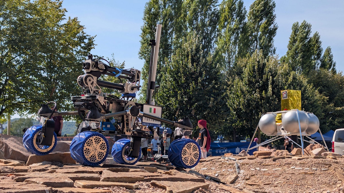
FORTUNA is Team DIANA’s flagship planetary exploration rover, designed to operate in Mars-like environments and tackle the challenges of autonomous off-road mobility. Its highly maneuverable double-bogie mobility system, combined with a compact, modular avionics architecture, delivers the reliability and redundancy required for demanding planetary exploration missions.
Team DIANA, from the Polytechnic University of Turin, has participated in the European Rover Challenge (ERC) since 2018. Held annually in Poland, the competition brings together university teams from around the world to test their robotic systems in a realistic Mars Yard that simulates the conditions of the Martian surface. In 2026, the team also aims to compete in the prestigious University Rover Challenge (URC) at the Mars Desert Research Station in Utah, USA. If selected, DIANA would become the first Italian team to participate in the competition.
FORTUNA integrates advanced autonomous navigation, AI-based perception, and a robust onboard software stack that enables it to navigate complex terrain, avoid obstacles, and execute missions with limited human intervention. Its six-degree-of-freedom robotic arm supports maintenance operations, sample collection, and scientific experiments using interchangeable end effectors and dedicated payloads.
Testing and Validating the Differential System of a Mars Exploration Rover.pdf
A critical component of the rover is its differential suspension system, which distributes loads across the wheels while maintaining ground contact on uneven terrain. To ensure the system could withstand the demanding conditions expected during planetary exploration, Team DIANA conducted an extensive experimental validation campaign using Dewesoft data acquisition hardware and software. The following sections describe the testing methodology and present the validation results.
FORTUNA differential suspension system
The differential suspension system is a critical component of any planetary rover, distributing loads across the wheels to maintain traction and stability on uneven terrain. For the FORTUNA rover, Team DIANA developed a differential bar configuration optimized for low weight, high stiffness, and mechanical efficiency. After multiple design iterations, the team achieved a lightweight structure without compromising strength or performance.
The system connects to the rover’s central chassis through dedicated pivots that transfer loads between both sides of the mobility system. This configuration allows all wheels to maintain ground contact while traversing obstacles up to 20 cm high, improving stability on challenging terrain.
The differential assembly is built around a central carbon fiber bar connected to the rotating assembly through spherical joints integrated with the central pivot. These joints compensate for small axial and radial misalignments that occur during operation, ensuring smooth load transfer and reliable performance.
On the opposite side, two carbon fiber lateral links connect the differential bar to the mobility system’s rotation pivots using the same spherical joint design. The extensive use of carbon fiber significantly reduces overall system weight while maintaining the high structural stiffness required for planetary exploration, where achieving the best possible weight-to-performance ratio is essential.


Objectives of the experimental validation
During the design phase, Team DIANA carefully evaluated the loads acting on the FORTUNA differential suspension system to properly size its structural components and ensure reliable performance under the most demanding operating conditions. Multibody dynamics simulations performed in MSC Adams showed that the composite bars would primarily experience axial tensile and compressive loads.
To validate these simulation results, the team collaborated with Dewesoft, which provided data acquisition hardware, measurement instrumentation, and technical support throughout the experimental testing campaign. The primary objective was to correlate experimental measurements with the numerical model and verify that the differential system remained structurally stable under realistic operating conditions.
A key focus of the validation was confirming the absence of elastic instability, commonly known as buckling. This failure mode can occur in slender structural components subjected to compressive loads, causing them to lose stability and deform laterally even when the material itself has not reached its strength limit. Demonstrating that the differential system remained free of buckling was therefore essential to validating its structural design.
Experimental test setup


A dedicated experimental setup was developed to acquire the physical quantities of interest and was interfaced directly with the Dewesoft data acquisition system.
The instrumentation used during the testing campaign included:
2CA-SX load cell with a 200 kg full-scale capacity;
Micro-Measurements strain gauges in rosette configuration;
Software DewesoftX.
The tests were carried out by reproducing the most severe operating conditions expected during rover operation.
To simplify data interpretation and improve sensor integration, a dedicated differential system for experimental activities was developed, maintaining the same operating principle as the configuration installed on the rover.


Measuring forces and structural deformation
To directly measure the forces acting on the differential suspension system, the team used a 200 kg load cell capable of measuring both tensile and compressive loads.
The sensor, based on a Wheatstone bridge configuration, was connected directly to the Dewesoft data acquisition (DAQ) system.
Using DewesoftX software, the team configured calibration and signal conditioning to minimize measurement errors and ensure high-quality data throughout the testing campaign.
To evaluate structural deformation, the team manufactured a dedicated shaft with a low surface roughness to improve strain-gauge bonding and reduce potential measurement errors. The strain gauges were installed in a laboratory cleanroom to ensure controlled conditions and consistent sensor adhesion.
The measurement setup used strain gauges mounted at 90° intervals, with opposite pairs connected in a half-Wheatstone bridge configuration. This arrangement enabled the team to monitor bending on two independent planes and accurately evaluate the structural behavior of the differential bar under load.
Careful sensor alignment during installation was essential to obtaining reliable, repeatable measurements and minimizing installation-induced errors.


Experimental results and validation
The initial multibody dynamics simulations, performed using MSC Adams, allowed the evaluation of the differential system behavior under various operational configurations of the rover.
The simulations were first conducted with the rover without the robotic arm, and the robotic arm was then subjected to motion over rough terrain. Among the results obtained, the most significant correspond to the static configuration, i.e., with the rover at rest and in the absence of external dynamic excitations.
In this condition, as identified in the linear region of the graph in Figure 5 for the axial stress component (blue line), the numerical analysis indicates a negative axial force acting on the differential bar. This condition, therefore, indicates compression of the structure.
The value estimated during the design phase is approximately −9 N, consistent with the static configuration of the rover without the robotic arm and in the absence of significant dynamic excitations.


To perform a first validation of the numerical model, the force acting on the system was experimentally measured using the load cell installed on the setup, keeping the rover in the static configuration and replicating the same conditions used in the simulation.
As shown by the experimental results, the system also exerts an axial compressive force of approximately −9 N on the differential bar in the real configuration, indicating a strong correlation with the numerical model predictions developed during the design phase.
The agreement between simulation and testing enabled a valid validation of the system's static behavior in the configuration without the robotic arm.
Given the particularly small magnitude of the applied force, we deemed it unnecessary to perform a strain assessment using strain gauges in this configuration. Such low load levels, in fact, generate extremely limited deformations, close to the acquisition system's noise threshold, and are difficult to distinguish from potential signal disturbances.


The subsequent numerical simulations were instead carried out considering the rover equipped with the robotic arm.
In this configuration, the system is subjected to different loading conditions due to the introduction of additional masses and the moments generated by the arm relative to the differential system's pivots.


The results show a reversal of the axial force sign relative to the previous configuration. The differential bar is now subjected to a tensile force of approximately 48.8 N.
This behavior is directly related to the load distribution imposed by the robotic arm, which modifies the rover's static equilibrium and the force transfer within the mobility system.
A further aspect emerging from the analysis concerns the increase in the magnitude of the forces acting during the traversal of the same simulated path. The presence of the arm, in fact, significantly increases the dynamic loads transmitted to the differential system, making this configuration the most demanding structurally.
To validate this configuration, an experimental test campaign was conducted to replicate operating conditions used in the numerical simulation phase.
We therefore subjected the rover to a path with various obstacles and geometric discontinuities to generate realistic loading conditions for the differential system.
In a first step, the presence of the axial tensile force in the static configuration with the arm installed was verified. In this case, too, the experimentally observed behavior was consistent with the predictions of the numerical model.


The force measured using the load cell was approximately 40.3 N in tension. The discrepancy with respect to the value obtained from the simulation can be attributed to several factors, including simplifications introduced in the numerical model, unmodelled friction, manufacturing tolerances in the system, and slight oscillations caused by rover positioning during the experimental test. Despite these discrepancies, the obtained values remain consistent with the behavior predicted during the design phase.
The most relevant aspect emerging from the tests, however, concerns the overall magnitude of the forces acting on the system. The recorded loads are, in fact, compatible with the structural sizing and do not indicate conditions that would lead the system towards elastic instability or buckling phenomena.
To further verify this assumption, the data acquired from the strain gauges installed on the differential bar were analyzed.
The adopted configuration involved two half-Wheatstone bridge setups oriented on different planes. The first half-bridge involved placing one strain gauge on the upper surface and one on the lower surface of the bar, while the second half-bridge was configured with strain gauges positioned laterally on the bar.
This solution enabled monitoring of potential bending phenomena along the two main structural planes, enabling a comprehensive evaluation of the bar's behavior during the tests.


The analysis of the acquired data did not reveal any significant dimensional variations attributable to elastic instability phenomena.
The values recorded by the strain gauges are, in fact, consistent with extremely small deformations and coherent with the expected structural behavior. The graph in Figure 9 illustrates the strain trends measured by the two half-Wheatstone bridges installed on the differential bar.
In particular, the first plot shows the signals acquired from half-bridge 1 (HB1), which consists of strain gauges mounted on the bar's upper and lower surfaces. The second plot, shown in blue, represents the data acquired from half-bridge 2 (HB2), configured with strain gauges installed laterally on the right and left sides of the differential bar.
This configuration enabled the exclusion of buckling phenomena on both principal planes, even under the most demanding operating conditions investigated during the experimental campaign.
The slight oscillations observed in the acquired signals are primarily attributable to electrical noise and environmental vibrations affecting the measurement system, and do not compromise the overall validity of the results.
Conclusion: validating the Mars Rover differential system
The experimental testing campaign confirmed the structural performance of FORTUNA’s differential suspension system and demonstrated a strong correlation between the numerical simulations and the experimental measurements. These results validated the design assumptions established during the development phase and increased confidence in the system’s reliability under demanding operating conditions.
The analysis showed that the differential system is primarily subjected to axial tensile and compressive loads, while bending stresses remain negligible, even in the most demanding operating configurations. Measurements acquired using the load cell and strain gauges also confirmed the absence of elastic instability or buckling, verifying the robustness of the structural design.
By combining numerical simulations with high-precision experimental measurements acquired using the Dewesoft data acquisition system, Team DIANA successfully verified the effectiveness of its differential suspension design. The results demonstrate that careful geometric optimization and the use of lightweight composite materials can deliver a stiff, reliable, and weight-efficient solution for planetary exploration rovers operating in challenging environments.
Acknowledgements
DIANA would like to thank Riccardo Petrei, Davide Carniani, Elvira Rufolo, and the entire team at Dewesoft Italy for their availability, technical expertise, and support throughout the experimental activity. Their contribution was essential in gaining a deeper understanding of the project requirements and ensuring a high level of technical assistance.
DIANA looks forward to the possibility of collaborating again in future activities and projects.