




Detecting Fatigue Damage in Aluminum Wheel Rims Using Acoustic Response Analysis
Arkadiusz Rychlik
University of Warmia and Mazury
August 4, 2026
Fatigue damage in lightweight aluminum wheel rims can begin long before visible cracks appear, making early detection difficult. Researchers at the University of Warmia and Mazury in Olsztyn developed a fatigue-testing platform that combines cyclic loading with acoustic response analysis. Using a Dewesoft SIRIUSi data acquisition system, they detected changes in the response spectrum that indicated advanced damage before the component failed.
Detecting fatigue damage in aluminum wheel rims
Fatigue failure remains one of the most critical degradation mechanisms affecting lightweight aluminum structures. In automotive wheel rims, cyclic loading may initiate microscopic damage long before visible cracks appear, making early detection particularly challenging.
The University of Warmia and Mazury in Olsztyn is a public university in Olsztyn, Poland. The core structure of the university is based on an agreement between three institutions of higher learning already established in the city: the Academy of Agriculture and Technology, the Pedagogical Institute, and the Warmia Institute of Theology.
To investigate the relationship between fatigue degradation and dynamic response, researchers in the university’s Department of Vehicles and Machinery at the Faculty of Technical Sciences developed a dedicated experimental system that combines cyclic fatigue loading with periodic vibration-based condition assessment. The objective was to determine whether changes in acoustic response characteristics could reveal structural degradation before catastrophic failure.
Challenges of detecting fatigue damage in aluminum wheel rims
Traditional fatigue evaluation methods often rely on visual inspection, strain measurements, or post-failure analysis. However, these approaches may not provide sufficient information about the progressive deterioration occurring during the fatigue process.
The research team sought to develop a repeatable methodology for monitoring structural changes under fatigue loading using non-destructive dynamic measurements.
A key requirement was the ability to perform repeated measurements under controlled conditions while maintaining consistent excitation and signal acquisition quality throughout the experiment.
IFTS–DRMS fatigue testing system
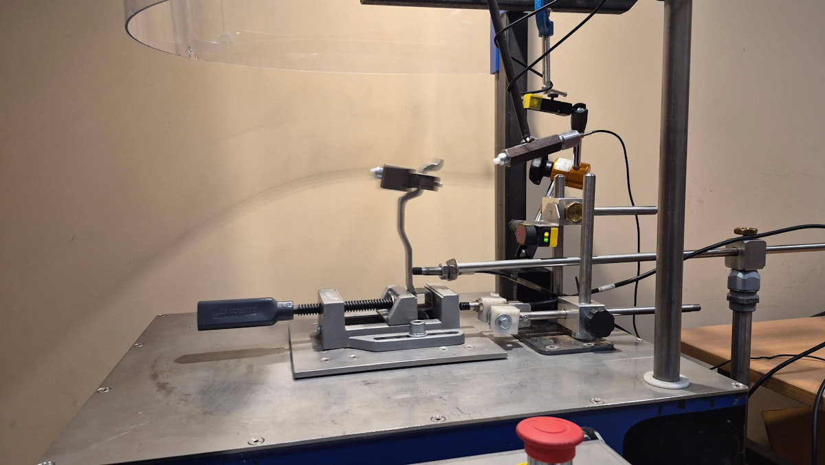
To achieve these objectives, we developed a dedicated Inertial Fatigue Test Stand with Dynamic Response Monitoring System (IFTS–DRMS).
The system combines cyclic inertial loading with periodic impact-excitation measurements, enabling monitoring of the evolution of dynamic response during fatigue degradation.
The experimental setup consisted of:
Wheel-rim specimens extracted from aluminum automotive wheel rims,
An inertial fatigue loading mechanism,
A custom impact excitation system,
Acoustic response measurement instrumentation,
Automated specimen condition monitoring and failure detection.
Figure 1 presents the dynamic response measurement setup integrated with the fatigue test stand.


During fatigue testing, specimens remained mounted within the stand while cyclic loading was continuously applied. Dynamic response measurements were performed at predefined intervals to evaluate changes in structural behavior.

Dewesoft SIRIUS data acquisition system
Signal acquisition was performed using a Dewesoft SIRIUS data acquisition system.
The measurement chain consisted of:
Dewesoft SIRIUSi-6xACC-2xACC DAQ system.
ROGA RG-50 free-field measurement microphone.
Custom-built impact hammer with a mass of 0.315 kg instrumented with a KD36 accelerometer (sensitivity: 5.21 mV/(m/s²)).
DewesoftX data acquisition and signal processing software is operating at a sampling frequency of 100 kHz.
The microphone captured the acoustic response of the specimen following impact excitation, while the hammer instrumentation ensured repeatable excitation conditions throughout the test campaign.


The recorded data were exported for further analysis and evaluation of fatigue-related changes in dynamic response characteristics.
Fatigue testing procedure
Specimens extracted from wheel-rim profiles were subjected to cyclic fatigue loading using the IFTS–DRMS system.
At predefined intervals, fatigue loading was interrupted, and dynamic measurements were performed using impact excitation. The resulting acoustic response signals were recorded and analyzed in the frequency domain.
This procedure enabled comparison of the specimen’s dynamic behavior at different stages of fatigue degradation.
The final successful measurement was acquired after approximately 420,000 loading cycles. Shortly afterward, the specimen fractured during handling before the next scheduled measurement, indicating that the acquired data reflected a near-failure condition.
Acoustic response analysis results
Figure 6 compares the average power spectral density (PSD) of the acoustic response measured in the initial condition and after approximately 420,000 fatigue cycles.


The results demonstrate that fatigue degradation significantly affected the amplitude of the acoustic response. Although the dominant resonance frequencies remained nearly unchanged, the energy distribution within the response spectrum evolved considerably as the specimen approached failure.
These observations indicate that acoustic response monitoring can provide valuable information regarding the progression of fatigue damage even before a visible fracture occurs.
Fatigue crack development and failure analysis
The fatigue crack continued to grow until the specimen failed completely, as shown in Figure 7. The crack pattern confirmed that the dynamic response changes measured near the end of the test were linked to advanced fatigue damage. This shows that acoustic response monitoring can detect structural deterioration before complete failure.


Key results
The investigation demonstrated several important observations:
Dynamic response monitoring successfully identified changes associated with fatigue degradation,
Significant PSD amplitude growth was observed at approximately 314 Hz, 440 Hz, and 531 Hz before specimen failure,
Resonance frequencies exhibited only minor shifts during degradation,
Acoustic response measurements provided a sensitive indicator of structural condition,
Dewesoft SIRIUS enabled stable and repeatable acquisition of high-quality measurement data throughout the fatigue testing campaign.
Conclusion
The IFTS–DRMS system combined fatigue loading and dynamic response monitoring in a single test platform.
Using the Dewesoft SIRIUS data acquisition system, researchers tracked small changes in the acoustic response throughout the test. They detected clear spectral changes before the specimen failed.
The results show that vibration and acoustic monitoring can help assess fatigue damage in lightweight structural components. The method also provides a basis for further development of structural health monitoring techniques.