




Automated Temperature Sensor Calibration in a Climatic Chamber
Iñigo Mendizabal Gorostizu-Orcaiztegui
CETEST and Mondragon University
October 7, 2026
Accurate temperature measurement is essential in railway testing to ensure safety, performance, and compliance with industry standards. To reduce calibration costs and sensor downtime, CETEST developed an automated in-house temperature sensor calibration system using a climatic chamber. The solution combines reference instrumentation, custom hardware, and automated data acquisition to deliver reliable, traceable, and efficient calibration results.
Temperature measurement in railway testing
CETEST is an accredited, independent testing and validation laboratory based in northern Spain, providing testing, engineering, and monitoring services worldwide. The company supports leading railway manufacturers and operators through regulatory approval processes for new and refurbished vehicles, components, and systems.
CETEST is also a core testing partner of Mondragon University. Engineering students regularly complete dual training and cooperative study programs, combining academic work with practical experience at CETEST.
Accurate measurement is essential in railway testing to ensure safety, reliability, and performance. CETEST performs a wide range of static and dynamic tests on railway vehicles and components, where temperature is often a critical measurement parameter. Monitoring and recording temperature helps assess system behavior, verify compliance with international standards, and identify potentially unsafe operating conditions.
Typical applications include:
Rotating components: Measuring gearboxes, bearings, and axle boxes to monitor friction-induced heating and verify lubrication performance across different operating speeds.
Climatic testing: Performing full-scale and simplified HVAC and thermal comfort tests in climatic chambers to evaluate heat transfer, environmental conditions, and energy consumption.
Vehicle dynamics: Measuring passenger thermal comfort together with vibration exposure.
Braking systems: Monitoring wheel and brake disc temperatures during demanding braking cycles to evaluate thermal behavior, stopping performance, and deceleration limits.
CETEST uses different temperature sensor technologies depending on the application. Resistance temperature detectors, including PT100 and PT1000 sensors, are commonly used where high accuracy and stability are required.


RTD sensors operate on a simple physical principle: the electrical resistance of a metal changes with temperature. In PT100 and PT1000 sensors, the sensing element is made of platinum. As the temperature increases, its resistance changes in a predictable manner, allowing temperature to be determined accurately from the measured resistance.
Infrared sensors are also used when non-contact measurement or higher temperature ranges are required. Depending on the sensor, they can cover approximately −20 °C to 3000 °C and offer response times in the millisecond range, making them suitable for dynamic temperature measurements.
The challenge of external temperature sensor calibration
Until now, CETEST has calibrated all its temperature sensors in external laboratories. Although this approach worked well from a technical standpoint, it caused two big problems:
High costs: calibration fees and shipping costs, and
Low equipment availability. Sensors were out of service for more than a month, which limited test planning and inventory management during busy seasons.
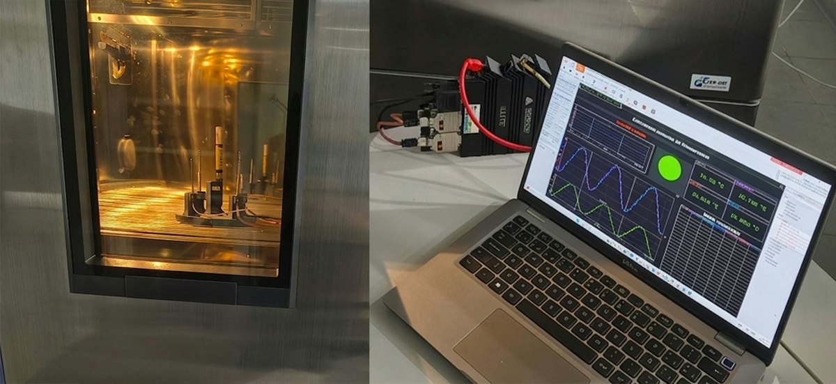
To solve these problems, increase autonomy, and reduce downtime, we developed an automated, standardized, and traceable internal calibration system for temperature sensors. The calibration will be performed in a climatic chamber within the temperature range of -40 to 180 °C and a relative humidity range of 0% to 100%.
Finally, to record all calibration data and automatically collect sensor and reference data at each stabilization point, we will use an Iolite 6x STG.
Automated in-house temperature sensor calibration
Reference standards for temperature calibration
To establish a reliable reference for the calibration process, CETEST selected a high-accuracy industrial thermo-hygrometer. The instrument measures both temperature and relative humidity and is suitable for use in controlled industrial environments, with a temperature accuracy of ±0.1 °C.
This reads better because it removes “To address this problem,” which is vague, and avoids “These probes are used in specific industrial environments,” which sounds generic. It also makes the role of the instrument in the calibration process clearer.


Signal conditioning for the reference sensor
To integrate the reference probe with the data acquisition system, CETEST designed a dedicated power supply box that powers the sensor and provides its temperature and humidity outputs as analog voltage signals. The signals range from 0 to 1 V. For temperature, this corresponds to a measurement range of −100 to 200 °C and a sensitivity of approximately 3.33 mV/°C.
This setup enables stable and continuous acquisition of the reference measurements, supporting the accuracy, reliability, and traceability of the calibration process.
After the reference sensor was externally calibrated, its sensitivity and offset were calculated and adjusted to achieve the required measurement accuracy. These values were then entered into the corresponding channel in DewesoftX to convert the measured voltage into the correct reference temperature.
DewesoftX is data acquisition and signal processing software used for measurement, data recording, visualization, and analysis.


3D sensor support for climatic chamber calibration
To ensure consistent calibration conditions, CETEST designed and manufactured a custom 3D support for positioning the sensors and the reference probe inside the climatic chamber. The support keeps all sensors uniformly positioned relative to the reference and the chamber environment, minimizing temperature and humidity differences between measurement points.
The support was designed in SolidWorks to ensure accurate and repeatable sensor positioning.


Because the climatic chamber operates from −40 °C to 180 °C, the support material had to withstand a wide temperature range. After evaluating suitable materials, CETEST selected PEEK.
PEEK is a high-performance thermoplastic with strong resistance to elevated temperatures and demanding environmental conditions. Compared with conventional plastics such as nylon or ABS, it is better suited to the temperature range required for this calibration setup.
Temperature sensor calibration procedure
The calibration of temperature sensors will be performed using a comparison method with a reference temperature sensor.
The standards used in the calibration of temperature sensors are as follows:
A reference temperature sensor.
Calibrated data acquisition equipment to read the reference sensor's output voltage and the temperature sensor's output resistance. In our case, we will use the Dewesoft IOLITE 6xSTG model, as explained in the corresponding section. Additionally, Dewesoft DSI adapters will convert the temperature sensor signals.
A thermos-hygrometer will record the environmental conditions in the calibration room.
Temperature calibration measurement chain
To automate the temperature sensor calibration process, CETEST developed a measurement chain that acquires data simultaneously from the reference sensor and the sensor under calibration. The system conditions, records, and compares both signals throughout the calibration sequence.
The necessary equipment to carry out the calibration is:
Reference temperature sensor.
The temperature sensor is to be calibrated.
Climatic chamber.
DSI-RTD adapter or DSI-TH-K.
Two differential BNC-DB9 cables (DB9 pinout: In+ → pin 2, In− → pin 7).
Two power supplies.
PC.
Figure 5 shows a simplified diagram of the measurement system.


Temperature sensor calibration setup in DewesoftX
Once the measurement chain is connected, configure the input channels in DewesoftX. The reference temperature and humidity signals are acquired through analog voltage inputs.
For each reference channel, define the measured physical quantity and enter the sensitivity and offset values determined during calibration. DewesoftX then converts the measured voltage signal into the corresponding temperature or humidity value.


For RTD temperature sensors, DSI-RTD adapters are automatically detected by DewesoftX in the analog input setup, allowing the channel to be configured directly for temperature measurement. Thermocouples can be configured in a similar way using DSI-TH-K adapters.


Once the measurement chain is assembled and configured, the climatic chamber is programmed with the calibration sequence. Calibration points are set at 0%, 10%, 30%, 50%, 70%, 90%, and 100% of the sensor’s operating range. The sequence includes both increasing and decreasing temperature cycles, repeated three times to evaluate sensor stability and repeatability.


In DewesoftX, data hold indices capture sensor readings at each stabilization point. The software also calculates each sensor’s deviation from the reference value and generates an alarm if the error exceeds the specified tolerance.


The acquisition rate is set to 100 Hz, resulting in an effective bandwidth of approximately 95 Hz. This provides a clean signal with reduced noise and improves the reliability of the recorded data. Because temperature changes relatively slowly, additional low-pass filtering with a cutoff frequency of 10 or 20 Hz can be applied to further reduce measurement noise.
Calibration correction and measurement uncertainty
The calibration results are used to determine the correction for each measurement point and the associated measurement uncertainty.
The correction y is defined as the difference between the reference temperature T_\text{ref} and the value indicated by the temperature sensor under calibration T_\text{med}:
y = Tref − Tmed


Measurement uncertainty is evaluated by considering the contributions from both the reference temperature sensor and the calibrated data acquisition system. The calculation follows the Guide to the Expression of Uncertainty in Measurement (GUM), which provides the general framework for evaluating and expressing measurement uncertainty.
Using this method, the mean uncertainty is calculated for each calibration point.
Temperature sensor calibration results
Once data acquisition is complete, the recorded measurements and graphs are analyzed to evaluate sensor performance. The analysis focuses on stability, repeatability, and deviation from the reference value throughout the calibration sequence.


The recorded data are then exported to a dedicated calibration template for automated processing. The template calculates corrections, errors, and associated measurement uncertainties and generates the final calibration results. These results are used to determine whether the sensor meets the defined acceptance criteria and is suitable for further use.
The template also generates the calibration certificate automatically, helping ensure full traceability and consistent documentation of all relevant calibration data in a clear and structured format.


Automated calibration results and benefits
The developed system enables automated, reliable, and traceable temperature sensor calibration in a climatic chamber. By bringing the process in-house, CETEST can reduce calibration time and costs while improving sensor availability.
The reference thermo-hygrometer, signal conditioning hardware, and custom 3D support help maintain consistent measurement conditions and reliable acquisition of both reference and sensor signals. The programmed calibration sequence, with multiple measurement points, increasing and decreasing cycles, and repeated runs, supports evaluation of sensor stability and repeatability.
Measurement uncertainty is evaluated according to GUM guidelines, providing a consistent and traceable basis for assessing calibration results.
The Dewesoft DAQ system and DewesoftX support channel configuration, real-time visualization, data acquisition, and automated processing. Automated calculations and certificate generation further improve efficiency, reduce manual work, and support consistent documentation.
Overall, the system gives CETEST greater control over its calibration process while maintaining reliable measurement performance and traceability.